Sélection de la langue

Search

Sommaire du brevet 2047931 

Énoncé de désistement de responsabilité concernant l'information provenant de tiers

Une partie des informations de ce site Web a été fournie par des sources externes. Le gouvernement du Canada n'assume aucune responsabilité concernant la précision, l'actualité ou la fiabilité des informations fournies par les sources externes. Les utilisateurs qui désirent employer cette information devraient consulter directement la source des informations. Le contenu fourni par les sources externes n'est pas assujetti aux exigences sur les langues officielles, la protection des renseignements personnels et l'accessibilité.

Disponibilité de l'Abrégé et des Revendications

L'apparition de différences dans le texte et l'image des Revendications et de l'Abrégé dépend du moment auquel le document est publié. Les textes des Revendications et de l'Abrégé sont affichés :

  • lorsque la demande peut être examinée par le public;
  • lorsque le brevet est émis (délivrance).
(12) Demande de brevet: (11) CA 2047931
(54) Titre français: PAROI EN ELEMENTS PREFABRIQUES
(54) Titre anglais: PREFABRICATED UNIT BUILDING WALL
Statut: Réputée abandonnée et au-delà du délai pour le rétablissement - en attente de la réponse à l’avis de communication rejetée
Données bibliographiques
(51) Classification internationale des brevets (CIB):
  • E04B 02/00 (2006.01)
  • E04B 01/10 (2006.01)
(72) Inventeurs :
  • WOLF, JOHANN (Autriche)
  • WOLF, JOHANN (Autriche)
(73) Titulaires :
  • JOHANN WOLF
  • JOHANN WOLF
(71) Demandeurs :
(74) Agent: BORDEN LADNER GERVAIS LLP
(74) Co-agent:
(45) Délivré:
(22) Date de dépôt: 1991-07-25
(41) Mise à la disponibilité du public: 1992-01-28
Requête d'examen: 1992-01-20
Licence disponible: S.O.
Cédé au domaine public: S.O.
(25) Langue des documents déposés: Anglais

Traité de coopération en matière de brevets (PCT): Non

(30) Données de priorité de la demande:
Numéro de la demande Pays / territoire Date
A 1582/90 (Autriche) 1990-07-27

Abrégés

Abrégé anglais


ABSTRACT
PREFABRICATED UNIT BUILDING WALL
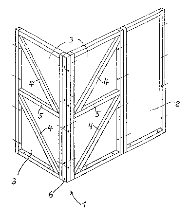
A wall consisting of corner units (1) and wall units
(2) where the corner units are frames (3) meeting at an angle,
and have oblique bracings (4) and cross braces (5) and are
connected with one another in the zone of the meeting angle by
corner posts (6) or the equivalent. The wall units (2) have
rectangular frames.

Revendications

Note : Les revendications sont présentées dans la langue officielle dans laquelle elles ont été soumises.


THE EMBODIMENTS OF THE INVENTION IN WHICH AN EXCLUSIVE PROPERTY
OR PRIVILEGE IS CLAIMED ARE DEFINED AS FOLLOWS:
1. Wall for a building composed of prefabricated wall
units having closed rectangular frames, and corner units joined
thereto, the corner units comprising braced and/or rigidified
frames meeting at an angle with respect to one another.
2. Wall according to claim 1, the corner units having
bracings extending obliquely downwardly toward the apex of the
meeting angle formed between their frames.
3. Wall according to claim 1 or 2, each corner unit
having a ratio of width to height of 1 : 2, each corner unit
frame being subdivided by a cross brace in the center of its
height, the bracing extending downwardly at 45°.
4. Wall according to claims 1, 2 or 3, the corner unit
frames consisting of wood and being joined together in a zone at
the apex of their meeting angle by a vertical corner post.
5. Wall according to claims 1, 2 or 3, the corner unit
frames being selected from steel and reinforced concrete and
being directly connected to one another.

6. Wall according to claims 1, 2, 3, 4 or 5, the corner
units being joined to the respective wall unit frames at
respective frame uprights and being connected at respective
horizontal plates with a concrete floor.
7. Wall according to claims 1, 2, 3, 4, 5 or 6, the
corner unit frames and the wall unit frames being lined with
enamaled metal panels on their outwardly facing sides.

Description

Note : Les descriptions sont présentées dans la langue officielle dans laquelle elles ont été soumises.

;~ t~ ~ ~ ;J r j ~
~ 1 ~
The invention relates to a wall oP pref~bricated wall
units with closed rectangular frames.
The conventional arrangements for buildings which can
be assembled from prefabricated units, for stiffening the
building comprise diagonal braces in the individual structural
units which absorb lateral wind load in the assembled
structure. The diagonal reinforcements interfere with a free
choice of arrangement for windows and doors, and appropriately
fashioned units are required. Introducing insulating material
into the units is made difficult by such bracing. The
acute-angled corners formed by the bracing can be filled with
insulating material only with difficulty and/or by taking
considerable time so that often cold-conducting bridges are
formed at these locations. Likewise, the subsequent window or
door placing is difficult. Manufacture of these units is
substantially more expensive because of these diagonal braces
with the many inclined cuts involved and, as a consequence of
the differently designed windows and door units, requires
variegated bracings and/or trimmed components.
DOS 2/143,579 discloses wall units and ceiling units
made of wood which are rigidified on the inside by
perpendicularly intersecting strips and are lined on the outside
with panels. Corner units have the same structure. This
building mode suffers from the drawbacks described above.
DOS 2,627,261 describes a wall construction composed

2,~
of joined profiled members~ especially of metal, where the
interstices are filled with concrete. This construction is very
expensive and uneconomic.
Wall and corner units consisting of beams are known
from W0 8~/05485. The strength of these units can be achieved
solely by the dimensioning o~ the individual components. This
entails considerable expenditure in material.
Herein described is a novel design of corner units,
with wall units having a simple structure which exhibit good
stiffness but do not limit the placing of doors, windows, and
the like.
In a wall of the type described the corner units have
braced and/or rigidified frames meeting at an angle to one
another.
Using such corner units, the wall unit~ can be
designed as simple, rectangular frames. The cornar and wall
units can have any desired design of outside or inside lining.
More particularly in accordance with the invention
there is provided a wall for a building composed of
prefakricated wall units having closed rectangular frames, and
corner units joined thereto, the corner units comprising braced
and/or rigidified frames meeting at an angle with respect to one
another.

2 ~ ~ ~ ' i ? j
Embodimen~s of ~he invention will now be described
with reference to the accompanying drawings, wherein:
Figure 1 shows a building in perspective view with a
roo~ indicated by dashed lines,
Figures 2 and 3 show two embodiments in plan view,
Figure 4 show~ in an oblique view, and
Figure 5 shows, in plan view, prefabricated components
embodying this invention made of wood.
Descri~tion of the Preferred Embod ments
As illustrated in Figures 2 and 3, for a pre~abricated
building, wall units 2 can be laid *lush with the outsides of
the corner units 1, or they can be placed offset toward the
inside, as in Figure 3, so as to particularly emphasize the
corners o~ the building. This method of construckion of~ers a
great variety of design possibilities and great adaptation to
the prevailing purpose of use ~or the building.
For example, buildings for commercial purposes can be
lined on the outer walls with shaped aluminum panels, and the
corner units 1 can be lined with enameled metal sheets of any
desired color. For residential purposes, mixed designs can be
executed, some with wall units placed flush and some offset
toward the insid2 (Figure 3).
Further, concrete corner units 1, or corner units 1
lined or faced with enameled metal panel~ give additional design
. '
' ` '
.

i(s~J~j
possibilities in conjunction with wall units 2 which are faced
with wood.
An important criterion for a rugged corner design
which is to withstand the shear caused by wind load is that the
corner units l consist of angularly arranged frames 3, as
illustrated in Figure 4. The bracings 4 of these frames extend
obliquely downwardly toward the apex of the angle formed by the
frames 3. These bracings transmit the shear toward the floor.
Each of the two frames 3 is subdivided in this arrangement by a
cross brace 5. With a ratiQ of width to height for the frames 3
of 1 : 2, and with a cross brace 5 located in the center of the
height dimension, two respective square component frames are
obtained, and the bracings 4 extend downwards at 45.
Where a corner unit 1 is made of wood, the two frames
3 are joined at a corner post 6, most preferably by screws or
bolts. The wall units 2 here are likewise made of wooden frames
and are preferably joined at their respective uprights to the
respective frame 3 by means of screws or bolts. The frames 3
and the wall units 2 have a uniform width, for example of
llO cm. All of the units are preferably connected at their
bottom plates by screws or bolts to the floor, for example a
concrete floor.
Corner units 1 of steel or rein~orced concrete have
the same structure as can be seen from Figure 4 showing the
wooden construction. The only difference is that the frames 3
are joined directly at the apex of the meeting angle, i.e.
without a specific corner post member.

Dessin représentatif
Une figure unique qui représente un dessin illustrant l'invention.
États administratifs

2024-08-01 : Dans le cadre de la transition vers les Brevets de nouvelle génération (BNG), la base de données sur les brevets canadiens (BDBC) contient désormais un Historique d'événement plus détaillé, qui reproduit le Journal des événements de notre nouvelle solution interne.

Veuillez noter que les événements débutant par « Inactive : » se réfèrent à des événements qui ne sont plus utilisés dans notre nouvelle solution interne.

Pour une meilleure compréhension de l'état de la demande ou brevet qui figure sur cette page, la rubrique Mise en garde , et les descriptions de Brevet , Historique d'événement , Taxes périodiques et Historique des paiements devraient être consultées.

Historique d'événement

Description Date
Inactive : CIB de MCD 2006-03-11
Le délai pour l'annulation est expiré 1994-01-25
Demande non rétablie avant l'échéance 1994-01-25
Inactive : Demande ad hoc documentée 1993-07-26
Réputée abandonnée - omission de répondre à un avis sur les taxes pour le maintien en état 1993-07-26
Demande publiée (accessible au public) 1992-01-28
Toutes les exigences pour l'examen - jugée conforme 1992-01-20
Exigences pour une requête d'examen - jugée conforme 1992-01-20

Historique d'abandonnement

Date d'abandonnement Raison Date de rétablissement
1993-07-26
Titulaires au dossier

Les titulaires actuels et antérieures au dossier sont affichés en ordre alphabétique.

Titulaires actuels au dossier
JOHANN WOLF
JOHANN WOLF
Titulaires antérieures au dossier
S.O.
Les propriétaires antérieurs qui ne figurent pas dans la liste des « Propriétaires au dossier » apparaîtront dans d'autres documents au dossier.
Documents

Pour visionner les fichiers sélectionnés, entrer le code reCAPTCHA :


Pour visualiser une image, cliquer sur un lien dans la colonne description du document (Temporairement non-disponible). Pour télécharger l'image (les images), cliquer l'une ou plusieurs cases à cocher dans la première colonne et ensuite cliquer sur le bouton "Télécharger sélection en format PDF (archive Zip)" ou le bouton "Télécharger sélection (en un fichier PDF fusionné)".

Liste des documents de brevet publiés et non publiés sur la BDBC .

Si vous avez des difficultés à accéder au contenu, veuillez communiquer avec le Centre de services à la clientèle au 1-866-997-1936, ou envoyer un courriel au Centre de service à la clientèle de l'OPIC.

({010=Tous les documents, 020=Au moment du dépôt, 030=Au moment de la mise à la disponibilité du public, 040=À la délivrance, 050=Examen, 060=Correspondance reçue, 070=Divers, 080=Correspondance envoyée, 090=Paiement})


Description du
Document 
Date
(aaaa-mm-jj) 
Nombre de pages   Taille de l'image (Ko) 
Revendications 1992-01-27 2 39
Abrégé 1992-01-27 1 12
Dessins 1992-01-27 2 43
Description 1992-01-27 4 142
Dessin représentatif 1999-07-05 1 19
Correspondance de la poursuite 1992-01-19 2 28
Courtoisie - Lettre du bureau 1992-03-03 1 44