Note: Descriptions are shown in the official language in which they were submitted.
LEUCOCYTE DEPLETING FILTER DEVICE AND METHOD OF USE
The invention relates to filter devices for
removing leucocytes and other deleterious material
from leucocyte-containing liquids such as blood.
For example, the invention relates to the removal of
leucocytes from blood in an extracorporeal circuit.
Patients undergoing open heart surgery have the
pumping functions of the heart and the gas exchange
functions of the lungs temporarily replaced by
various apparatus in an external (extracorporeal)
circuit. In the last 30 years, technological
advances related to the components of these
extracorporeal systems have provided significant
benefits to these patients. For example, completely
disposable components of an extracorporeal circuit
and associated blood-contacting surfaces have been
fabricated, which eliminate adverse patient
reactions due to contamination from trace amounts of
a previous patient°s blood supply.
During a typical operation requiring
extracorporeal circulation, blood from the
cardiovascular system of the patient is typically
taken from the patient and delivered through tubing
to an oxygenator which serves as an external lung.
Within the oxygenator, blood is exposed to an
appropriate percentage of oxygen and carbon dioxide.
The perfusate is drawn from the oxygenator by an
arterial pump and delivered to a blood filter, which
removes gaseous microemboli, fat emboli, aggregates
- 1 -
and microaggregates, and other debris. From the
filter, the blood is usually returned directly to
the vascular system of the patient. Ancillary
circuits, typically including one to three
additional pumps and a small reservoir, may be used
to salvage blood from the operative site. The
salvaged blood is delivered to a cardiotomy
reservoir where it can he filtered and stored until
the surgeon returns the blood directly or indirectly
through the oxygenator to the patient's
cardiovascular system. By these means, the
requirement for external blood replacement is often
minimized.
The technological improvements noted above have
focused on minimizing red cell damage in both the
main circuit, comprising the oxygenator, arterial
pump, and filter, and the ancillary blood salvage
circuits. However, the presence of these devices,
which are necessary for the transport and gas
exchange of the blood but nonetheless are foreign to
the patient's body, may have a deleterious effect on
leucocytes, or white blood cells, in the blood.
Contact between the internal surfaces of these
foreign devices and the leucocytes may elicit an
immune response and/or may result in the formation
and release of a host of toxic mediators, and what
is commonly referred to as oxygen-free radicals.
Leucocytes are a type of blood cell in the
immune system which constitute the principal means
of defense against antigens, such as infection by
pathogenic microorganisms and viruses, and probably
also against most cells that undergo transformation
into cancer cells. Leucocyte activation, the
leucocytic monitoring and arming functions, proceeds
from a complex series of biochemical interactions,
- 2 -
~~t~~ J-~~.
typically terminating in engulfing and digesting the
antigen. Tf the leucocytes have been so activated,
but lack an appropriate antigenic target, the
leucocytes may inflict damage to internal organs,
particularly ischemic tissues, i.e., tissues in
which no blood is flowing such as the heart and
lungs during certain surgical procedures. This
effect, called ''reperfusion injury", is well known
and is commonly caused by leucocyte activation as a
result of leucocyte contact with foreign matter such
as the large internal surface area of an
extracorporeal circuit.
The activated leucocytes associated with
reperfusion injury release both proteolytic enzymes,
which may lead to the destruction of cellular
function and structure, and oxygen metabolites
("free radicals") which could lead to death.
Extracorporeal circuit-induced activated leucocytes
have been implicated in microcirculatory stasis,
leucocyte sequestration, vasospasm, organ
destruction, interstitial edema, microvascular
occlusion (including myofibrillar necrosis,
mitochondrial disruption, and nuclear chromatin
clumping), lung endothelium damage, and the release
of chemotactic factors.
Laucocytes have also beer. implicated as the
singular cause or a major contributory factor in a
growing number of transfusion complications,
including non-hemolytic febrile reactions,
alloimmunization, viral transmission (e. g.,
Cytomegalovirus, Human T-cell Lymphotropic Virus
Type I), immune suppression and modulation, graft
versus host reactivity, and refractoriness to
platelets. Moreover, with increasing frequency, the
most common leucocyte, the granuloeytic neutrophil,
- 3 -
has been implicated as the mediator of tissue
destructive events in a variety of disorders,
including reper.fusion injury, respiratory distress
syndromes, rheumatoid arthritis, skin disorders and
ulcerative colitis. The commonality which pervades
these pathologies is the neutrophil's ability to
release a number of agents which can disrupt and
destroy normal cellular function, dissolve
connective tissue, and cause injury to organs.
It has also been shown that circulating
leucocytes contribute to or mediate ischemic and
reperfusion injury during organ preservation,
particularly following extended preservation of the
heart-lung bloc commonly required during
cardiopulmonary bypass operations (CPB). Leucocytes
have also been associated with increased oxygen
radical activity, pulmonary edema, and
vasoconstriction.
According to the present invention, a filter
assembly for removing leucocytes and other
deleterious matter from a liquid, such as blood,
generally comprises a housing and a fibrous depth
filter. The housing has an inlet and an outlet and
defines a liquid flow path between the inlet and the
outlet. The fibrous depth filter is positioned
inside the housing across the liquid flow path and
includes a fibrous structure for decreasing the
leucocyte content of the liquid at a flow rate
greater than about 25 milliliters per minute.
Filter assemblies which embody the invention
may include a filter element having one or more of
the following characteristics: a hollow, generally
cylindrical configuration; an upstream portion which
has a larger pore size than the downstream portian:
a total fibrous surface area greater than about 2
- 4 -
square meters and a critical wetting surface tension
(CWST) of 53 dynes per centimeter or more. The
filter assemblies may have a total hold-up volume in
the range from 70 cubic centimeters to 400 cubic
centimeters and may further comprise a porous
degassing element for removing gas from the liquid,
a liquophobic membrane which allows gas but not
liquid to escape from the housing, and a vent for
removing gas from the housing.
ZO The present invention also provides a method
for removing leucocytes and other deleterious matter
from a liquid, such as blood. The method generally
comprises decreasing the leucocyte content of the
liquid by passing the liquid through a fibrous depth
filter. Methods embodying the invention may include
passing the liquid through a fibrous depth filter
having one or more of the following characteristics:
a hollow, generally cylindrical configuration; an
upstream portion which has a larger pore size than
the dosrinstream portion; a total fibrous surface area
greater than about 2 square meters: and a CWST of 53
dynes per centimeter or more. The method may
further comprise holding up no less than 70 cubic
centimeters and no more than 400 cubic centimeters
of the liquid; repeatedly recirculating blood
through a housing in an extracorporeal circuit'
separating gas from the liquid: or venting the gas
from the housing.
Filter assemblies and methods embodying the
present invention are particularly advantageous.
First, they remove leucocytes very effectively.
Leucocytes are not only trapped in the interstices
of the fibrous depth filter but they also adhere to
the surfaces of the fibers in the depth filter.
Having a total fibrous surface area greater than
_ 5 _
~t~~~~~~
about 2 square meters, the fibrous depth filter
provides ample surface area on which the leucocytes
can adhere. Having a CWST of 53 dynes per
centimeter or greater, the fibrous depth filter can
have a CWST greater than the surface tension of the
liquid, allowing the liquid to readily wet the
fibrous depth filter, actively seep into all of the
interstices of the filter element, and completely
contact the ample surface area of the fibers.
Further, filter assemblies and methods
embodying the present invention are capable of
removing leucocytes while maintaining a large flow
of liquid through the fibrous depth filter for a
considerable span of time without clogging or
plugging. Conventional filters may remove
leucocytes at low flows, e.g., 5-l0 milliliters per
minute, but embodiments of the present invention are
capable of removing leucocytes at much greater flow
rates, even hundreds of times greater. As noted
previously, because the CWST of the fibrous depth
filter can be 53 dynes per centimeter or greater
and, therefore, can be greater than the surface
tension of the liquid, the liquid flows through the
depth filter with minimal resistance due to the
effects of surface tension. In addition, because
the fibrous depth filter can have a hollow,
cylindrical configuration and an upstream region
with a larger pore size than the downstream region,
the depth filter resists clogging or plugging. The
hollow, cylindrical configuration presents a large
surface area to liquid flowing outside-.in through
the depth filter and, therefore, spreads
contaminants more thinly around the filter. The
upstream region with the larger pores allows the
smaller contaminants to.penetrate deeper into the
- 6 -
depth filter rather than accumulate on the surface
of the filter to block liquid flow. Thus, although
embodiments of the present invention are nonetheless
effective at low flow rates, they are capable of
removing leucocytes at very large flow rates for
extended periods of time. For example, Ieucocytes
may be removed from a liquid such as blood at a flow
rate up to six liters per minute for three to four
hours and, in some cases up to ten hours, without
clogging or plugging.
While filter assemblies and methods embodying
the present invention are capable of maintaining a
large flow rate, they hold up very little of the
liquid when flow ceases. In many situations, the
liquid being filtered is whole blood obtained
directly from a patient. For example, during a
surgical operation or during autologous transfusion,
blood can be removed from the patient and circulated
through an extracorporeal circuit which includes a
filter assembly of the present invention, and then
returned to the patient. When the operation is
completed and flow through the extracorporeal
circuit ceases, the blood which remains in the
extracorporeal circuit, in particular, in the filter
assembly, cannot be returned to the patient. Filter
assemblies embodying the present invention hold up
so little blood that only about 70 cubic centimeters
to about 400 cubic centimeters remain in the filter
assembly after flow ceases even though the flow rate
during the operation can be as high as six liters
per minute.
Filter assemblies and methods embodying the
present invention have a wide variety of uses. For
example, a filter assembly may be used to remove
leucocytes and other deleterious matter from blood
_ 7 _
~~'~:~
passing through it, while simultaneously allowing
other blood components, such as red cells and
platelets, to be returned undamaged to the patient.
A filter assembly or method embodying the
present invention may be used in an extracorporeal
circuit, such as is described above, and/or may be
employed for therapeutic applications, including but
not limited to autologous transfusion,
leucopheresis, apheresis, or dialysis. Thus, the
device and method have application whenever blood or
a leucocyte-containing liquid is brought into
contact with external circuitry, and thence returned
to the body or specific organs.
A filter assembly or method embodying the
present invention may also be used for cardioplegia
or coronary perfusion in order to perfuse and
maintain safe levels of metabolic activity within
tissues and organs. Moreover, the filter assembly
or method can be used for myocardial infarcted
patients to reduce subsequent damage during
reperfusion in the affected heart region.
In addition, a filter assembly in accordance
with the present invention can be used in
cytoreductive therapy or in any therapeutic or
clinical regimen in which leucocyte depletion is
beneficial. For example, certain hematological
disorders result in a marked increase in blood
viscosity due to a high number of circulating
leucocytes. This phenomenon, called leukostasis,
can result in tissue and organ damage.
Extracorporeal circulation of blood through a device
in accordance with the present invention can be used
to reduce the leucocyte count, thus reducing blood
viscosity.
Also, as noted above, leucocyte depletion has
_ g -
been successful in reducing or eliminating the
deleterious effects attributed to a wide variety of
injuries, diseases, or conditions. Passing the
patient's blood through a device in accordance with
the present invention can be used in clinical or
therapeutic regimens in which leucocyte depletion is
beneficial.
FIG. 1 is a sectional side view of an exemplary
filtering apparatus embodying the present invention.
FIG. 2 is a partial cut away top view of the
filtering apparatus of FIG. 1.
FIG. 3 is an illustration of a liquid filtering
system incorporating the filtering apparatus of
FIG. 1.
The present invention provides for a leucocyte
depletion filter assembly for removing leucocytes
and other deleterious matter from a leucocyte-
containing liquid, the filter assembly comprising:
(a) a housing having an inlet and an outlet and
defining a liquid flow path between the inlet and
the outlet; and (b) a fibrous depth filter
positioned inside the housing across the liquid flow
path and including a fibrous means for decreasing
the leucocyte content of the liquid at a flow rate
greater than 25 milliliters per minute.
The present irve.~.tion also provides far a
leucocyte depletion filter assembly for removing
leucocytes and other deleterious matter from a
leucocyte-containing liquid, the filter assembly
comprising: (a) a housing having an inlet, an
outlet, and a vent and defining a liquid flow path
between the inlet and the outlet; (b) a degassing
mechanism communicating with the vent for removing
gas from the liquid; and (c) a depth filter
positioned in the housing across the liquid flow
r c
path.
The present invention further provides for a
leucocyte depletion filter assembly for removing
leucocytes and other deleterious matter from a
leucocyte-containing liquid, the filter assembly
comprising: (a) a generally cylindrical housing
having first aTld second chambers, an inlet which
allows tangential inflow into the first chamber, an
outlet which allows outflow from the second chamber,
and a vent; (b) a porous degassing element
positioned between the first and second chambers to
remove gas from the liquid; (c) a liquophobic
membrane covering the vent and communicating with
the degassing element to allow gas but not the
liquid to flow through the vent; and (d) a hollow,
cylindrical filter element positioned in the second
chamber and comprising a mass of microfibers having
a CWST of 52 dynes/cm or greater and a graded pore
size over at least a substantial radial portion of
the microfibrous mass, the interior of the hollow
filter element communicating with the outlet.
The present invention further provides for a
method for removing leucocytes and other deleterious
matter from a leucocyte-containing liquid comprising
passing at least 25 milliliters per minute of the
liquid through a fibrous depth filter.
The present invention also provides for a
method for removing leucocytes and other deleterious
matter from a leucocyte-containing liquid
comprising: (a) directing the liquid through a
housing. (b) separating gas from the liquid; (c)
venting the gas from the housing; and (d) passing
the liquid through a fibrous depth filter positioned
within the housing, thereby decreasing the leucocyte
content of the liquid.
- 10 --
The present invention also provides for a
method of treating blood in an extracorporeal
circuit comprising: (a) repeatedly circulating the
blood through a housing; (b) separating gas from the
blood; (c) venting the gas from the housing; and (d)
passing the blood through a fibrous depth filter
positioned within the housing, thereby decreasing
the leucocyte content of the blood.
The present invention also provides for a
method of treating blood in an extracorporeal
circuit comprising: (a) directing the blood through
a housing; (b) separating gas from the blood; (c)
venting the gas from the housing; and (d) passing
the blood through a fibrous depth filter positioned
within the housing, thereby decreasing the leucocyte
content of the blood.
The present invention also provides for a
method for removing leucocytes and other deleterious
matter from a leucocyte-containing liquid
comprising: (a) directing the liquid through a
fibrous depth filter at a flow rate of up to six
liters per minute, and (b) removing a clinically or
therapeutically significant amount of leucocytes
from the liquid.
The present invention also provides for a
method of treating blood in an extracorporeal
circuit comprising: (a) repeatedly circulating the
blood through a fibrous depth filter at a flow rate
of up to six liters per minute; and (b) removing a
clinically or therapeutically significant amount of
leucocytes from the liquid.
A filter assembly in accordance with the
present invention comprises a housing, having an
inlet and an outlet, and a filter element disposed
in the housing for decreasing the leucocyte content
- 11 -
and removing other deleterious matter from a
leucocyte-containing liquid. Leucocyte-containing
liquid, as used herein, refers to blood, including
whole blood, treated blood, such as blood diluted
with a physiological solution, and one or more blood
components, such as plasma or packed red cells, as
well as other leucocyte- or leucocyte precursor
cell-containing liquids. Deleterious matter, as
used herein, includes activated and non-activated
leucocytes, fat emboli, microaggregates, and other
debris. Preferred embodiments of the invention may
also comprise a degassing mechanism cooperatively
arranged with the housing for removing gaseous
emboli from the liquid.
The filter assembly may be configured in a
variety of ways in accordance with the invention.
For example, the filter assembly may include a solid
filter element which may have a disk-like or
cylindrical shape and may be positioned in a housing
to filter liquid flowing longitudinally or axially
through the filter element. The inlet and outlet of
the filter assembly would then communicate with
opposite ends of the filter element and the side of
the filter element would be sealed against the
housing to prevent bypass of the liquid around the
=filter element.
Alternatively, the filter assembly may include
a hollow filter element which may have a cylindrical
shape and may be disposed in the housing to filter
liquid flowing laterally or radially through the
filter element. For example, to filter liquid
flowing inside/out through the filter element, the
inlet and outlet of the filter assembly would be
arranged to respectively communicate with the
interior and exterior of the hollow filter element.
- 12 -
In the illustrated embodiment, the filter
assembly is arranged to filter liquid flowing
outside/in through the filter element. This
arrangement is preferred because it provides a
filter element with a large surface area in a
compact housing.
Any housing of suitable shape to provide an
inlet and an outlet for liquid and a space for a
filter element disposed between the inlet and outlet
can be employed. A preferred embodiment of the
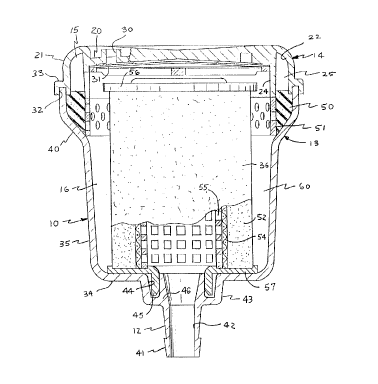
filter assembly comprises a generally cylindrical
housing 10 having an inlet 11 and an outlet 12, as
shown in Figures 1 and 2. Housings can be designed
to accept a variety of shapes of filter assemblies.
For example, a square or octagon shaped housing and
other possible forms designed to accommodate a
similarly shaped filter element would in principle
all be functional, provided that adequate flow area
is provided by the filter element. These shapes are
within the scope of the claimed invention.
Any housing of suitable configuration to
reliably contain the liquid and define a liquid flow
path through the filter element can be employed. A
preferred embodiment of the filter assembly
corprises a housing 10 which generally includes two
parts, a body 13 and a cover 14, and defines upper
and lower chambers 15, 16. The cover 14 has a
shallow, generally cylindrical configuration and
includes a generally flat top wall 20 and a
downturned, generally cylindrical side wall 21.
In a preferred embodiment, the cover 14
includes the inlet 11, as shown in Figure 2. The
inlet 11 may be variously configured. For example,
the inlet 11 may comprise a nipple 23 which defines
- 13 -
s L~ r '~~ C
2J
an inlet passage 22 and may be molded integrally
with the cover 14. In the illustrated embodiment,
the inlet 11 is configured to receive the end of a
tube (not shown). In a preferred embodiment, the
inlet passage 22 is horizontal and opens through the
side wall 21 of the cover 14 in a direction
tangential to the side wall 21.
The cover 14 may also be provided with an
accessory port 27 and an annular baffle 24. The
accessory port 27 may be used to provide pressure
measurements or samples of the liquid being
filtered. When it is not in use, the accessory port
27 may be capped. The annular baffle 24 is
preferably concentric with and spaced inwardly from
the side wall 21. The baffle 24 may be formed
integrally with the cover 14, extending downwardly
from the top wall 20, and may be generally
coextensive with the side wall 21, forming a
circular channel portion 25 in the upper chamber 15.
An opening 26 in the baffle 24 allows the circular
channel 25 to communicate with a vent in the cover
14.
The vent allows gas to escape from the housing
and may be configured in a variety of ways. For
example, it may comprise a nipple with a manually
operable valve. Hcwaver, in a preferred embodiment,
the vent comprises one or more holes 30 spaced
around the top wall 20 of the cover 14. A porous,
liquophobic membrane 31 may cover the holes 30
allowing gas but not liquid to escape from the
housing. In a preferred embodiment, the liquophobic
membrane may be attached to the underside of the top
wall 20 of the cover 14 to allow a relatively free
flow of gas from the housing. The liquophobic
membrane may be variously configured. For example,
- 14 -
it may comprise a polytetrafluoroethylene membrane
having an absolute pore rating of about 0.2 ~S and a
polypropylene backing as a support.
The cover 14 and the body 13 may be joined in
any suitable manner. For example, the lower end of
the cover side wall 21 may include an annular
channel 32 formed in a flange 33 which is configured
to receive the open upper end of the body 13. The
cover 14 and the body 13 may then be joined at the
l0 channel 32, preferably by bonding or by welding,
including spin welding or ultrasonic welding.
The body 13 includes bottom and side walls 34,
35 and may be substantially coextensive in depth
with the height of the filter element 36. In a
preferred embodiment the side wall 35 of the body 13
generally has a smaller outer diameter than the side
wall 21 of the cover 14 but flares at the upper end
to grovide an inclined shoulder 40.
In a preferred embodiment, the body 13 includes
the outlet 12. The outlet 12 may be variously
configured. For example, the outlet 12 may comprise
a nipple 41 which defines an outlet passage 42 and
may be molded integrally with the body 13. In the
illustrated embodiment, the nipple 41 projects
axially down fram a boss 43 in the center on the
underside of the bottom wall 34 and is configured to
receive the end of a tube (not shown). An annular
groove 44 in the inside of the boss receives an
annular extension 45 which surrounds an extension 46
of the nipple 41 and which centrally locates the
filter element 36 in the body 13.
The housing may be fabricated from any
sufficiently rigid, impervious material which is
compatible with the leucocyte-containing liquid.
For example, the housing may be fabricated from a
- 15 -
metal, such as stainless steel, or from a polymer.
In a preferred embodiment, the housing is fabricated
from a plastic material, such as polystyrene,
polycarbonate, or polypropylene. In addition, all
of the surfaces of the housing which contact the
liquid are preferably liquophilic, i.e., readily
wettable by the liquid. For example, the internal
surfaces of the body 13 and the cover 14 may be
treated to achieve a high degree of liquophilicity,
e.g., by surface graft co-polymerization of hydroxyl
functional monomers. These liquophilic internal
surfaces then readily facilitate the release of gas
bubbles during the prep and priming operation. A
method of reducing the adhesion of bubbles in
medical equipment is disclosed in U.S. Patent
4,861,617.
The degassing element may be fashioned from any
material which causes small gas bubbles in the
liquid to coalesce and separate from the liquid. In
a preferred embodiment, the degassing element is a
porous structure such as a porous foam or sponge
material. In addition, the degassing element may be
treated with an anti-foaming agent to aid in
breaking down the film between bubbles, for example,
a compound of silicone and silica, such as Medical
Antifoam A, available from Dow Corning Mfg. Co.
The degassing element may have any suitable
conficjuration, preferably geometrically similar to
the shape of the housing, and is preferably
positioned in the housing between the inlet and the
filter element. For example, in the illustrated
embodiment, the degassing element comprises an
annular sponge 50 interposed between the upper and
lower chambers 15, 16. The annular sponge 50 may be
- 16 -
20~'~9~~3
located in the housing 10 by an annular, perforated
ring 51 which preferably constitutes, in effect, an
axial extension of the baffle 24. The inclined
shoulder 40 holds the annular sponge 50 and
perforated ring 51 in place in the flared portion of
the housing body 13.
The illustrated embodiment of the filter
assembly includes a degassing element 50 as well as
a housing 10 having a tangential inlet 11 and a vent
30, all for removing gas from the liquid before the
liquid contacts the filter element 36. Of course,
the gas may be removed from the liquid by a separate
device before the liquid enters the filter assembly.
The filter assembly then need not include a
degassing element, a tangential inlet, or a vent.
The housing may then simply be only slightly larger
than the filter element.
In accordance with one aspect of the invention,
the filter element may be fashioned to decrease the
leucocyte content of a leucocyte-containing liquid
which is passed through the filter element. The
filter element may be fashioned in a variety of ways
to effectively remove the leucocytes, as well as
other deleterious matter from the liquid. For
example, the filter element preferably comprises a
depth filter. The depth filter may preferably
comprise a mass of fibers, such as a mass of
microfibers. The fibers may be made from any
material compatible with the liquid and may be
untreated or may be treated in a variety of ways to
make the filter element even more effective. The
fibers may be bonded, fused, or otherwise fixed to
one another or they may simply be mechanically
entwined.
- 17 -
The fiber diameters and/or the void spaces
between the fibers may have a substantially constant
size along the dimensions o:E the filter element or
they may vary in a continuous or stepwise manner.
Further, the filter element may be configured as a
flat sheet, a corrugated sheet, a solid body such as
a disk or cylinder, or a hollow body such as a
hollow cylinder and may include additional
structures such as end caps, edge seals, a cage, a
core, or a wrap.
As shown in Figure 1, a preferred embodiment of
the filter element 36 has a hollow, generally
cylindrical configuration and comprises a wrap 52, a
fibrous mass 53, a porous element 54, a perforated
core 55, an upper blind end cap 56, and a lower open
end cap 57. The filter element 36 is preferably
disposed within the lower chamber 16 in the housing
10 and is smaller in diameter than the side wall 35
of the body 13 so that an annular space 60 is left
between the side wall 35 and the filter element 36.
The interior of the filter element 36 communicates
with the centrally located outlet 12.
The wrap 52 surrounds the fibrous mass 53 and
serves to protect the fibrous mass 53 from damage
when the filter element 36 is assembled. The wrap
52 may comprise any suffici'ntly flexible, porous
material, preferably having a relatively large pore
size. For example, the wrap 52 may be a sheet of
spun-bonded, non-woven, polypropylene fibers.
The porous element 54, which preferably has a
pore size no greater than about 40 microns, is
disposed coaxially adjacent to the downstream
surface of the fibrous mass 53, e.g., around the
interior of the fibrous mass 53. The porous element
54 may be fashioned from any compatible porous
- 18 -
~o~~~~~
membrane or woven or non-woven material, including a
mesh or a screen. The porous element 54 serves
principally as a final filter to remove, for
example, any aggregates which escape the fibrous
mass 53 or form at the downstream portion of the
fibrous mass 53.
The perforated core 55 is disposed within and
adjacent to the interior of the porous element 54
and serves principally to support the fibrous mass
53 and the porous element 54 against the
differential pressure across the filter element 36.
Consequently, the perforated core 55 may be
fashioned from any suitably rigid material including
a metal such as stainless steel or a rigid polymer
such as polyolefin, polyester, or polyacrylate.
The end caps 56, 57 serve to direct the liquid
radially outside/in through the filter element 36.
Both end caps 56, 57 are preferably fashioned from
an impervious polymer, such as polypropylene, and
are fixed to the respective ends of the fibrous mass
53, the porous element 54, and the perforated core
55. Alternatively, the lower ends of the fibrous
mass, the porous element, and the perforated core
may be fixed directly to the bottom wall of the
body, eliminating the need for a lower end cap.
Aiternativeiy, the filtar element may be
designed for inside/out flow. The porous element
may then be disposed around the exterior of the
fibrous mass, the upper end cap may be an open end
cap, and the lower end cap may be a blind end cap.
The core may be omitted but a cage disposed
coaxially around the porous element to support the
fibrous mass and the porous element against the
pressure drop may be added. Of course, the housing
would be rearranged to permit the inlet to
_ 19 _
~o~~ot~~
communicate with the interior. of the filter element
and the outlet to communicate with the exterior of
the filter element.
The fibrous mass 53 may preferably be
configured as a mas~~ of non-woven, synthetic,
polymeric fibers. The fibers may be bonded, fused,
or otherwise fixed to one another, or they may be
substantially free of fiber-to-fiber bonding and
secured to each other by mechanical entanglement or
intertwining. The term "fibers" includes filaments,
and the term '°substantially free of fiber-to-fiber
bonding", as used herein, refers to the
characteristics of the fibers making up the fibrous
mass 53. Thus, although the fibrous mass 53 may
display random fiber-to-fiber bonding, such bonding
would not contribute in any material way to the
structural integrity of the filter element. A
preferred fibrous mass 53 is available from Pall
Corporation under the registered trademark Profile.
Polymeric materials particularly well suited
for the fibrous mass 53 include, but are not limited
to thermoplastics such as the polyolefins,
particularly polypropylene and polymethylpentene;
polyamides, particularly nylon 6, nylon 610, nylon
1C, nylon 11, nylon 12; and polyesters, particularly
polybutylene terephthalate and polyethylene
terephthalate. Other suitable, but less preferred,
polymers are addition polymers such as polyvinyl
fluoride, polyvinylidene fluoride and their
copolymers. The preferred material is pclybutylene
terephthalate.
The fibrous mass 53 may be produced by melt
blowing, in which molten resin is attenuated into
fibers by a high velocity stream of gas and
- 20 -
~~~~~~~J
collected as a non-woven web. As disclosed in U.S.
Patent No. 4,726,901, of the above noted materials,
some are better adapted to melt blowing of fine
fibers than are others. Material which are
particularly suited to melt blowing include
polyethylene, polypropylene, polymethylpentene,
Nylon 6, polyester PET (polyethylene terephthalate),
and polyester PBT (polybutylene terephthalate).
Others that have not yet been tested may be found.
Of the above listed resins, polyester PBT is a
preferred material because it also lends itself to
radiation grafting.
For some applications it may be desirable to
form the fibrous mass 53 directly on a mandrel
without the use of an internal support or core. For
most purposes, however, it is desirable that the
structure be able to withstand, without collapse or
loss of integrity, differential pressures in the
range from 0.5 psid to 175 psid, preferably in the
range from 0.5 psid to 135 psid. Accordingly, for
most applications, it is desirable to form the
fibrous mass 53, preferably by depositing melt-blown
fibers, on a hollow foraminous, or open, relatively
rigid central support member or core 55 after the
porous element 54 has been mounted to the core 55.
The fiber diameters may be substantially
constant throughout the fibrous mass 53.
Alternatively, the fiber diameters can be varied in
a continuous or step-wise manner from one part of
the fibrous mass 53 to another as measured in the
radial direction by varying the resin and fiberizing
air flow rates. Without intending to be held to a
specific theory, a combination of adsorption and
mechanical entrapment of leucocytes on fiber
surfaces is believed to be the mechanism for
- 21 -
~~~~~1 ~i~~
removing the leucocytes from a leucocyte-containing
liquid. Since the surface area of a given weight of
fibers is inversely related to the diameter of the
fibers, it is to be expected that finer fibers will
have higher capacity and that the quantity of
fibers, as measured by weight of fibers necessary to
achieve a desired efficiency, will be less if the
fibers used are smaller in diameter. Fiber
diameters as small as 1.5 to 2 micrometers or less
may be used to fashion the fibrous mass 53.
The fibrous mass 53 also preferably has a
substantially constant voids volume, typically in
the range of from 60 to 95 percent, more preferably
from 64 to 93 percent and even more preferably from
75 to 85 percent. When the fibrous mass 53
comprises polybutylene terephthalate (PBT) fibers,
the most preferred voids volume is about 85 percent.
The voids volume can be maintained substantially
constant by varying the forming roll bias force on
the cylindrical mass of fibers 53 as the structure
is formed on the rotating porous element 54 and core
55.
The removal rating can vary with the fiber
diameter. Thus, by varying the fiber diameter,
removal rating can be varied continuously or
stepwise from ane part of the fibrous mass 53 to
another in any desired manner in order to form a
filter element 36 having a graded pore structure.
For example, the fibrous mass 53 may include an
upstream portion having a removal rating as large as
120 micrometers and a downstream portion having a
removal rating as small as 0.5 micrometers, each at
a beta equal to 5000. More preferably, the upstream
portion may have a removal rating as large as 70
micrometers and the downstream portion may have a
- 22 -
~~~'~~t~~a
removal rating as small as 5 micrometers, each at a
beta equal to 5000. Such a fibrous mass may be
embodied with an upstream portion having coarser
fibers than the downstream portion.
In the illustrated embodiment, the annular
thickness of the fibrous mass 53 is preferably in
the range from 0.1 to 2 inches (2.5 mm to 5 cm),
more preferably in the range from 0.4 to 0.8 inch
(1.0 to 2.0 cm), and most preferably in the range
from 0.6 to 0.7 inch (1.5 to 1.8 cm). The outer
diameter of the fibrous mass is preferably in the
range from 2 to 3 inches (5 to 7.5 cm), more
preferably 2.2 (5.5 cm) inches. The length of the
fibrous mass 53 is preferably in the range from 2 to
3 inches (5 to 7.5 cm), more preferably 2.5 inches
(6.4 cm).
Although the fibers of the microfibrous mass 53
may remain untreated, they are preferably treated to
make them even more effective for removing
leucocytes and other deleterious matter. For
example, the fibers may be surface modified to
increase the critical wetting surface tension (CWST)
of the fibers.
As disclosed in U.S. Patent No. 4,880,548, the
CivST of a porous medium may be determined by
individually applying to its surface a series of
liquids with surface tensions varying by 2 to 4
dynes/cm and observing the absorption or non-
absorption of each liquid over time. The CWST of a
porous medium, in units of dynes/cm, is defined as
the mean value of the surface tension of the liquid
which is absorbed and that of the liquid of
neighboring surface tension which is not absorbed
within a predetermined amount of time. The absorbed
- 23 -
and non-absorbed values depend principally on the
surface characteristics of t:he material from which
the porous medium is made and secondarily on the
pore size characteristics of the porous medium.
Liquids with surface tensions lower than the
CWST of a porous medium will spontaneously wet the
medium on contact and, if the medium has through
holes, will flow through it readily. Liquids with
surface tensions higher than the CWST of the porous
medium may not flow at all at low differential
pressures and may do so unevenly at sufficiently
high differential pressures to force the liquid
through the porous medium. In order to achieve
adequate priming of a fibrous medium with a
leucocyte-containing liquid such as blood, the
fibrous medium preferably has a CWST in the range of
53 dynes/cm or higher. A CWST in the range from
less than 53 dynes/cm to 115 dynes/cm or greater is
preferred. Far example, a CWST of greater than 90
dynes/cm is expected to provide better passage and
protection of the platelets as they pass through the
porous medium. Methods for increasing the CWST in
the range of 53 dynes/cm or greater are disclosed in
U.S. Patent 4,925,5?2. Methods for increasing the
CWST in the range of 90 dynes/cm or greater are
disclosed in U.S. Patent 4,880,548.
For example, in whole blood, the cellular
components are suspended in blood plasma, which
typically has a surface tension of 73 dynes/cm.
Hence, if whole blood is placed in contact with the
microfibrous mass 53, spontaneous wetting will occur
if the microfibrous mass 53 has a CWST of 73
dynes/cm or higher.
The benefits conferred by modifying fibers to
CWST values higher than the natural CWST of
- 24 -
~~~~~~~J
synthetic fibers include:
(a) When priming using pressures lower than
the 0.2 kg/cmz, for example by gravity, the time to
achieve priming is significantly reduced. At 0,2
kg/cm2, the reduction is, however, so small as to be
difficult to measure.
(b) Fibrous media treated to convert the fiber
surfaces to a particular range of CWST perform
better with respect to efficiency and resistance to
clogging than do fibrous media with CWST values
outside of those ranges.
(c) The detrimental effects associated with
non-wetting, e.g., uneven flow through the porous
medium, are avoided.
(d) Devices made using unmodified synthetic
fibers are recommended to be flushed with saline
prior to use. This operation is sometimes
undesirable since it causes blood loss due to hold-
up within the complex tubing arrangement required,
adds to cost, operation time, and operation
complexity, and increases the probability that
sterility may be lost.
Surface characteristics of a fiber can be
modified by a number of methods, for example, by
chemical reaction including wet or dry oxidation, by
coating the surface by depositing a polymer thereon,
and by grafting reactions which are activated by
exposure to an energy source such as heat, a Van der
Graff generator, ultraviolet light, or to various
other forms of radiation. The preferred method is a
grafting reaction using gamma-radiation, for
example, from a cobalt source.
Radiation grafting, when carried out under
appropriate conditions, has the advantage of
considerable flexibility in the choice of reactants,
- 25 -
surfaces, and in the methods for activating the
required reaction. Gamma-radiation grafting is
particularly preferable because the products are
very stable and have undetectably low aqueous
extractable levels. Furthermore, the ability to
prepare synthetic organic fibrous media having a
CWST within a desired range is more readily
accomplished using a gamma radiation grafting
technique.
An exemplary radiation grafting technique
employs one or more of a variety of monomers each
comprising an ethylene or acrylic moiety and a
second group, which can be selected from hydrophilic
groups (e. g., -COOH, or -OH) or hydrophobic groups
(e.g., a methyl group or saturated chains such as
-CHZCHzCH3) . Grafting of the microfibrous mass 53
may also be accomplished by compounds containing an
ethylenically unsaturated group, such as an acrylic
moiety, combined with a hydroxyl group, such as,
hydroxyethyl methacrylate (HEMA). Use of HEMA as
the monomer contributes to a very high CWST.
Analogues with similar characteristics may also be
used to modify the surface characteristics of
(fibers.
Radiation grafting may increase fiber-to-fiber
bonding in a fibrous medium. Conseque~tly, a
fibrous medium which exhibits little or no
fiber-to-fiber bonding in an untreated state may
exhibit significant fiber-to-fiber bonding after the
fibers have been radiation grafted to increase the
CWST of the medium.
In a preferred embodiment of the invention, a
leucocyte-containing liquid enters a filter assembly
of the present invention through inlet passage 22
and into the circular channel 25 in upper chamber 15
- 26 -
20~~9~3
where a generally circular liquid flow pattern is
maintained by annular baffle 24 and the side wall 21
of the cover 14. This flow pattern produces a
centrifugal force which causes at least some of the
gas bubbles in the liquid, including any gross gas
bubbles, to separate from the liquid and move
inwardly and through the opening 26 in the baffle 24
into the central portion of the upper chamber 15.
The gas in the liquid is then vented from the filter
assembly through the holes 30 in the cover 14. In a
preferred embodiment of the invention, the gas
passes through a liquophobic membrane 31, which
covers the holes 30 and prevents the liquid from
escaping from the housing 10.
The liquid in channel 25 then passes, in a
preferred embodiment, through the annular sponge 50
and the perforated ring 51 to the space 60 in the
lower chamber. The degassing element 50 brakes the
rotational flow of the liquid and dissipates the
centrifugal forces which might otherwise tend to
force gas bubbles toward the filter element 36.
Also, as the liquid passes through the degassing
element 50, any smaller gas bubbles remaining in the
liquid coalesce into larger bubbles which, as the
liquid flows through the perforations in the
perforated ring 51, rise to the cantral portion. of
the upper chamber 15 and are vented from the filter
assembly as noted above. Thus, the liquid which
flows into the space 60 is substantially degassed.
In the embodiment of the invention
characterized as "outside/in,'° the degassed liquid
then passes from space 60 through filter element 36,
and into the interior of the filter element 36. The
filtered liquid then flows from the interior of the
filter element and exits from the housing 10 by
- 27 -
2~~'~~~~
passing through outlet 12.
In a preferred embodiment, the filter element
36 comprises a fibrous mass 53 having a graded pore
size, e.g., one wherein the removal rating varies
continuously or step--wise from a relatively large
size in the upstream portion of the fibrous mass to
a relatively small size in the downstream portion.
It is believed that filter element 36 decreases the
leucocyte content of the liquid by two mechanisms,
both operating simultaneously. One mechanism is by
adsorption of the leucocytes and other deleterious
matter onto the fibrous surfaces. Adsorption is a
function of the surface area of the fiber, which may
be in turn a function of fiber diameter: adsorption
may also be affected by the CWST of the fiber. The
surface area required for specific uses of the
filter assembly will vary according to the use. For
example, in an extracorporeal circuit with a flow
rate of as much as six liters/minute, the fiber
surface area of the filter element is preferably in
excess of two or three square meters. However, for
some applications, it will be desirable to have a
smaller quantity of fiber and/or fiber surface area
incorporated into a significantly smaller filter
assembly. An example is the "low flow" embodiment
described below. ,~anerally, the surface area ef the
fibers is sufficient to permit a large number of
contacts between individual fibers of the fibrous
mass and leucocytes and deleterious matter in the
liquid.
The second possible mechanism, removal by
filtration or mechanical entrapment, depends
principally upon maintaining the removal rating of
the filter medium within a specific range, but may
be marginally affected by the fiber CWST. In a
28 -
2~4~y~3
preferred embodiment, the removal rating is
preferably between 5 micrometers and 70 micrometers.
The smaller the fiber diameter, the higher the
surface area (per gram) and the smaller the
effective pore size.
The flow rate of liquid passing through a
filter assembly of the present invention can vary
according to the particular use and for any given
patient, but the flow rate should be maintained at a
level which does not harm or destroy erythrocytes or
platelets in the liquid. Embodiments of the
invention may filter as little as 25 milliliters per
minute or may have the capacity to filter up to 6
liters of liquid per minute, preferably 4 to 6
liters per minute, without clogging (i.e., without
increasing the pressure across the filter element to
above 15 psi), It should be apparent to one skilled
in the art that varying the surface area, CWST, flow
rate, removal rating, fiber diameter, and size of
the housing may effect leucocyte removal capacity.
Individually optimizing each of these parameters for
a specific intended use is considered within the
scope of the present invention.
The size of the filter assembly housing, the
surface area of the fiber, the pore diameter, and
the CWST all may affect the hold-up volume and the
priming efficiency of the filter assembly. Hold-up
volume refers to the amount of fluid required to
obtain filtered fluid at the output end of the
filter assembly. Hold-up volume also refers to the
amount of fluid which remains in the filter assembly
after it is taken off-line. Preferably, the hold up
volume is between 70 cc and 400 cc, typically
between 180 cc to 250 cc. One skilled in the art
will recognize that changing the design
- 29 --
characteristics of the filter assembly may affect
the hold-up volume. For example, increasing the
size of the filter housing may increase the hold-up
volume and removing the degassing element may
decrease the hold-up volume.
Priming efficiency refers to start-up of flow
from the patient through the filter and back to the
patient. An advantage of the filter assembly
embodying this invention is that the priming time
may be below 2 minutes. A short priming period may
be desirable in order to conserve nurse/technician
time, but may also be a life-saving issue when quick
administration is required as, for example, when
serious blood loss is unexpectedly experienced
during surgery.
While the devices described herein are
principally directed to a filter assembly having a
capacity of passing up to 6 liters/minute, filter
assemblies having a larger or smaller capacity can
be made. Included within the scope of the invention
is a filter assembly designated as a "low flow"
size, which has a flow rate of 3 liters/minute or
less, has approximately one-third the fiber surface
area and about one-half the capacity of the adult
device.
A filter assembly according to the present
invention has the capacity for up to 10 hours of
continuous removal of a clinically or
therapeutically significant amount of leucocytes and
other deleterious matter from a leucocyte-containing
liquid. However, many of the uses for which these
filter assemblies are suitable do not require 10
hours of filtration. For example, a cardiac bypass
operation may only require 6-8 hours; cardioplegia
may require only 2-4 minutes of filtration. Some
- 30 -
2~~'~~~
therapeutic protocols performed under emergency
conditions require only 10-20 seconds of filtration,
or several periodic or repeated filtrations of 10-20
seconds duration.
A filter assembly in accordance with the
present invention is capable of decreasing the
leucocyte content of the leucocyte-containing
liquid. This generally means removing a
therapeutically or clinically significant amount of
leucocytes from a leucocyte-containing liquid.
"Therapeutically or clinically significant amount"
refers an amount necessary to produce a beneficial
effect on the patient or animal receiving the
leucocyte depleted liquid. Such a beneficial effect
may be, for example, lessening reperfusion injury.
A therapeutically or clinically significant amount
can vary depending on the intended use and/or from
patient to patient. For example, a therapeutically
or clinically significant amount can be greater for
a cardiac bypass procedure than for cardioplegia.
However, removal of a therapeutically or clinically
significant amount can be and is routinely
determined by a doctor or technician for treating a
certain condition or disease as it pertains to the
specific patient or animal, and as it pertains to
the particular application.
For example, in an extracorporeal circuit, a
reference point (control) leucocyte count is
obtained immediately prior to the operation. Once
the operation begins, however, the patient is
constantly producing new leucocytes. Additionally,
the number of circulating leucocytes can be
increased merely through the doctor's alteration of
an operative condition, e.g., adding Hespan to the
circulating blood or increasing the pump speed.
- 31 -
204 ~ 1~
Furthermore, what is normal for one patient may be
abnormal for another. However, when an embodiment
of the invention is used in an extracorporeal
circuit, the leucocyte content is decreased,
resulting in a therapeutically or clinically
significant removal of leucocytes and demonstrably
less reperfusion injury. Also, an embodiment of the
invention may be used in an extracorporeal circuit
whereby the leucocyte content in the circulating
blood achieves eguilibrium, i.e., the amount of
leucocytes produced by the patient is substantially
offset by the removal of leucocytes using a
leucocyte depletion filter assembly according to the
present invention.
Furthermore, achieving leucocyte depletion in
and of itself, in relation to the initial leucocyte
count, may also be therapeutically or clinically
significant. Some therapies require the removal of
a certain number of leucocytes, e.g., to quickly
reduce a high leucocyte count to a lower one. Under
these conditions, the mare reduction in leucocyte
count may be therapeutically significant.
A filter assembly of the present invention may
be used in any procedure, therapy, operation, or
environment in which the removal of activated
leucocytes and deleterious matter is desirable ;,r
beneficial. Because leucocytes have the potential
for becoming activated upon contact with almost
anything ex-vivo, many applications exist for the
use of the filter assemblies of the present
invention in reducing the number of activated
leucocytes. While the filter assembly of the
present invention is particularly suited for
treating reperfusion-induced injury and/or achieving
leucocyte content equilibrium in an extracorporeal
- 32 -
~~~~'1:~~~
system, one skilled in the art will recognize other
contexts in which removal of leucocytes and other
deleterious matter in a liquid is desirable.
Without intending to limit the invention thereby,
the following provides examples of such uses.
A filter assembly of the present invention may
be used in any procedure which requires perfusion,
the passage of blood or other fluid through the
blood or lymph vessels of the body, using blood or
other, fluid which has been exposed to anything ex-
vivo (and therefore potentially containing activated
leucocytes). For example, a filter assembly
according to the present invention may be used in
any of the different techniques for protecting the
heart during ischemia (no blood flow) to the heart.
This is particularly evident in cardiac bypass
operations, including but not limited to left heart
bypass, femoral-femoral bypass, and aortic
occlusian. Also, leucocyte depletion has been
implicated in the amelioration of a number of
diseases or conditions, including the reduction of
pulmonary injury seen after CPB. Leucocyte
depletion appears to be the source of excellent
cardiac and pulmonary protection.
Without intending to limit the invention
thereby, an exemplary mode of operaticn for a~
embodiment of the invention is described by
reference to an extracorporeal (EC) system used in a
cardiopulmonary bypass (CPB) operation, as
illustrated in Figure 3, which shows the use of the
same filter under different capacity requirements.
In a CPB operation, the EC system commonly
comprises two loops. The first loop is a CPB
circuit for bypassing the patient's heart and lungs,
i.e., involved in rendering the heart ischemic. The
- 33 -
second loop is a cardiotomy circuit for collecting
blood from the operative site.
The EC system is primed by clamping the inlet
and outlet tubing of filter assembly 62. The rest
of the circuit is then primed using the bypass
circuit 66 by passing a priming fluid, such as
physiological saline, through the circuit at a flow
rate of 3-6 liters per minute. While maintaining
this flow, the clamp near the outlet of the filter
assembly is partially opened, allowing the filter
assembly to slowly fill with perfusate. The filling
time is preferably no more than 2 minutes. When the
priming fluid reaches the top of the filter, the
outlet clamp is removed, then the inlet clamp is
removed, and finally, the bypass circuit is clamped.
Once the system is primed, blood from the
cardiovascular system of the patient is channeled
into the CPB circuit through tubing into an
oxygenator 61 which removes carbon dioxide from the
blood and replaces it with oxygen. Oxygen is
delivered to the oxygenator 61 through an oxygen
filter 67. A pump 65 draws the oxygenated blood
through a filter assembly 62 of the present
invention, after which the filtered blood is
returned to the cardiovascular system of the
patient.
In the cardiotomy circuit, excess blood from
the surgical site is removed from the patient by
pump 63 and delivered to a cardiotomy reservoir 64.
Periodically, blood is drawn (or flows by gravity)
from the cardiotomy reservoir 64 into a filter
assembly 68 of the present invention, and then into
the oxygenator 61, where it is mixed with the blood
in the CPB circuit. Filter assemblies 62 and 68 may
be the same type of filter assembly, or they may be
- 34
2~~~7~~~~
different, but both are intended to be a filter
assembly according to the present invention. Thus,
a filter assembly of the present invention may be
used in environments which require a capacity of up
to 6 liters/minute, and cahich function at that level
(for example, the CPB circuit) or at a fraction of
that level (for example, the cardiotomy circuit).
In addition to the extracorporeal circuit
described above, another use of the filter
assemblies of the present invention include arterial
line filters, wherein the blood which flows through
the circuit comes from a patient's artery.
Typically, the pressure needed to produce
throughflow is the patient's blood pressure, but it
may be supplemented by an in-line pump. Similar to
the extracorporeal circuit noted above, arterial
line filters according to the invention have the
capacity to achieve leucocyte equilibrium. In use,
establishing leucocyte equilibrium indicates that
the leucocyte count when the filter assembly is
present is lower than the leucocyte count when the
filter assembly is not present.
More and more, cardiopulmonary bypass, as a
treatment or surgical protocol, is being extended to
non--cardiac applications as the knowledge concerning
the pathogenic nature of leucocytes increases. All
of these protocols may be improved by the inclusion
of a leucocyte depletion filter of the present
invention. For example, neurosurgeons use CPB in
operations involving the brain, the central nervous
system, and for the surgical repair of aneurysms,
fistulae, cerebral blood vessel anomalies, and blood
clots. CPB is also used in abdominal surgery to
provide a means of hypothermia and circulatory
arrest, and for isolating the abdominal venous
- 35 -
circulation. CPB may also be used in exposure
hypothermia to rewarm the victim and to offset or
eliminate myocardial damage. CPB is used for whole
body hyperthermia in the treatment of certain
cancers which are sensitive to elevated
temperatures. CPB may be used in isolated limb
perfusion in order to eliminate or reduce the
transport of toxic drugs and their side effects by
compartmentalizing blood flow. An embodiment of the
invention may be ir_corporated into any of these
protocols in order to achieve a clinically or
therapeutically significant effect.
Leucocyte depletion using a filter assembly of
the present invention may also ameliorate common
post-hypothermic pathologies.
In organ transplantation, the success of the
transplant may depend on suppressing the body's
natural tendency to rid itself of "foreign" tissue.
This can be achieved through a variety of powerful
immunosuppressive drugs, some of which kill
lymphocytes, and others of which stimulate
antibodies that inactivate lymphocytes. Included
within the scope of this invention are therapies
which combine the use of immunosuppressive drugs and
filtering circulating blood to remove deleterious
material from the bloodstream. yn liver
transplantation, massive blood loss and blood usage,
as well as reducing or eliminating donor organ
damage due to activated leucocytes, would benefit
from leucocyte depletion using a filter assembly of
the present invention.
Also included within the scope of this
invention. is the use of a filter assembly in
procedures with ischemic or ischemic-like episodes,
and for the reperfusion of blood for the whole body,
- 36 -
2fl479~3
for regional areas, or for isolated areas.
Leucocyte depletion, and the filter assemblies
of the present invention, may also be used
therapeutically for conditions in which leucocytes
play an interactive role with vascular endothelial
cells, including but not limited to Adult
Respiratory Distress Syndrome, allograft rejection,
shock states, coronary occlusion, and stroke.
The filter assembly of the present invention is
also particularly useful in therapeutic protocols
involving apheresis, either alone, or in conjunction
with other therapies. Leucopheresis, the selective
removal of leucocytes, may be used to obtain
leucocyte donation or as a therapeutic measure in
patients with elevated peripheral blood white cell
count. A wide number of disorders, diseases and
conditions may be diagnosed and/or treated using
leucopheresis. The filter assemblies of the present
invention may be used as or in a leucopheresis
apparatus.
A filter assembly of the present invention may
also be used in a wide variety of therapies for
treating autoimmune diseases (e. g., systemic lupus
erythematosus, rheumatoid arthritis, thyroiditis,
myasthenia gravis, multiple sclerosis, and certain
kinds of anemia). ~T~hese therapies includs radiation
of the lymph nodes, immunosuppressive drugs
developed as anti-cancer agents, and apheresis, a
sort of "blood washing" that removes diseased cells
and harmful molecules from the circulation. For
example, special leucocytes (e. g., labeled and/or
killer leucocytes) have been and are being developed
for the diagnosis and treatment of disorders
involving neoplastic cells. A filter assembly of
the present invention may be used to remove these
_ 37 _
special leucocytes after they have performed their
therapeutic or diagnostic function.
A filter assembly of 'the present invention may
also be used in the treatment of viral infections
and diseases. In the blood, viruses may be present
in the plasma, or may be associated with particular
types of leucocytes, with platelets, or with
erythrocytes. Leucocyte-associated viremia (the
presence of a virus in the bloodstream) is a feature
to of several types of infection, including but not
limited to infectious mononucleosis, measles, and
smallpox. Circulating leucocytes are themselves a
source of replicating virus; viremia is usually
maintained if there is a continued release of. the
l5 virus into the blood. For example, post-transfusion
mononucleosis (also known as postperfusion syndrome)
is a febrile condition commonly seen in patients
receiving massive blood transfusion (e. g., for open-
heart surgery). Cytomegalovirus (CMV) can be
20 isolated from the leucocytes of these patients.
Latent CMV infection also commonly occurs in
patients undergoing prolonged immunosuppressive
theragy for kidney transplants, leukemia, or cancer.
In addition, infectious mononucleosis is also
25 associated with Epstein-Barr Virus (EBV), typically
manifested by ieucopenia followed by leucocytosis.
Treatment of these conditions may be facilitated by
using a filter assembly of the present invention.
Although the foregoing invention has been
30 described in some detail by way of illustration and
example, it should be understood that the invention
is not limited thereto, and that many obvious
modifications and variations thereof can be made,
and that such modifications are intended to fall
35 within the scope of the appended claims.
- 38 -