Note: Descriptions are shown in the official language in which they were submitted.
2048069
.
AIR COMPRESSOR TANK MOUNT
Technlcal Fleld
The inventlon relates to air compressors and more
partlcularly to an lmproved mount for attachlng an alr
compressor and motor to a compressed alr storage tank.
Backqround Art
Small portable alr compressors are used ln many
ways. They provlde compressed alr for operating, for example,
spray guns, dusting nozzles, grlt blasters and pneumatic tools
and for lnflating tires. For llght duty appllcations where
only low air flow ls requlred and where constant alr pressure
ls not required, alr may be dellvered dlrectly from the
compressor to a tool or to flll a tlre, for example. However,
where more unlform alr pressure ls needed or where an
appllcatlon perlodlcally requlres greater alr flow at a
desired pressure than the compressor ls capable of dellverlng,
the compressor ls connected to flll a compressed alr storage
tank to a desired high pressure and compressed alr ls used
from the tank.
Alr compressors and compressed alr storage tanks are
often sold as assemblles. A base ls frequently welded to the
alr storage tank. An alr compressor and an electrlc motor
whlch drlves the alr compressor are deslgned to be mounted on
the tank by boltlng to the base. Where an alr compressor and
motor are manufactured as a compact stand alone assembly
wlthout an alr tank, there ls no convenlent way to
subsequently mount the assembly on a compressed alr storage
tank.
~.~,
~r 27905-51
s
2~806~
Dlsclosure of Inventlon
Accordlng to a broad aspect of the lnventlon there
ls provlded a mount for releasably attachlng an alr compressor
to a compressed alr storage tank, sald mount comprlslng first
and second brackets, each of said brackets having a saddle
portion with an edge shaped to abut the air tank, weldments
attaching said bracket edges to the air tank with said
brackets spaced apart, said first bracket havlng first and
second hooked ends, said second bracket having third and
fourth hooked ends, said air compressor having a bottom and
first and second opposed spaced grooves formed ad~acent said
bottom with said grooves spaced for said first groove
receiving said first and third hooked bracket ends and sald
second groove slmultaneously recelvlng sald second and fourth
hooked bracket ends, and means for retalning said hooked
bracket ends in said grooves.
The mounting brackets on the air tank are formed to
receive an optional handle. When the handle is attached to
the mounting brackets, it may extend over the compressor
`~ 20 assembly to approximately the center of gravity of the tank
and attached compressor assembly to facilitate carrying the
compressor and air tank. Or, if the alr tank ls provlded with
wheels at one end, the handle may extend from an opposite end
for llfting and wheeling the compressor and air tank.
Accordingly, it is an ob~ect of the invention to
provide an lmproved mount for attachlng a compressor and motor
assembly to a compressed alr storage tank.
Other ob~ects and advantages of the invention will
- 2 -
~,,~,
27905-51
2048069
be apparent from the following detailed descriptlon and the
accompanylng drawings.
Brlef Descrlpt lon of the Drawlnqs
Flg. 1 is a side elevational view showing a compact
alr compressor and motor assembly mounted on an air storage
tank according to the invention;
Fig. 2 is an end view thereof;
Fig. 3 is an enlarged fragmentary perspective vlew
showlng a portion of the alr storage tank, the attached
mountlng brackets and the handle wlth the air compressor and
motor assembly removed;
Fig. 4 is a side elevational view of one of the
mountlng brackets;
Fig. 5 ls an end vlew of the mountlng bracket of
Flg. 4i
- 2a -
27905-51
;~,
20~8~69
Fig. 6 is a side elevational view of the other of
the mounting brackets;
Fig. 7 is an end view of the mounting bracket of
Fig. 6;
Fig. 8 is a bottom plan view of an air compressor
and motor assembly showing grooves for attachment to the
mounting brackets; and
Fig. 9 is an end view of the compressor and motor
assembly of Fig. 8
Best Mode For Carrying Out The Invention
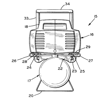
Referring to Figs. 1 and 2 of the drawings, a
portable air compressor assembly 15 is shown in
accordance with a preferred embodiment of the invention.
The assembly 15 consists of an air compressor 16 mounted
on a compressed air storage tan~ 17. The air compressor
16 is illustrated as having a compact molded plastic
housing 18 in which a reciprocating piston compressor
and an electric motor (not shown) are mounted. The air
tank 17 is cylindrical and is shown supported in a
horizontal position by a pair of leg brackets 19 and 20
welded to the tank 17. Or, one of the leg brackets 20
may be replaced with a pair of wheels 21 to make the
assembly 15 mobile.
A pair of brackets 22 and 23 are welded to the top
of the tank 17 for mounting the compressor 16. The
bracket 22 has two opposed upwardly and inwardly hooked
ends 24 and 25 and the bracket 23 has two opposed
upwardly and inwardly hooked ends 26 and 27. The air
compressor housing 18 is formed with integral grooves 28
and 29 extending along opposite sides of its bottom 30.
The grooves 28 and 29 are spaced and sized to slide onto
the hooked bracket ends 24-27 for mounting the air
compressor 16 on the air storage tank 17. When the air
compressor 16 is secured to the brackets 22 and 23, the
bracket ends 24 and 26 are retained in the housing
groove 28 and the bracket ends 25 and 27 are retained in
the housing groove 29. The air compressor slides onto
21~069
the brackets 22 and 23 until one or more of the hooked
ends 26 abuts a flange 31 or other suitable stop. A
screw 32 is then threaded into the housing 18 to retain
the air compressor 16 on the tank mounting brackets 22
and 23.
A tubular handle 33 may be attached to the brackets
22 and 23 to facilitate either carrying the assembly 15
or, when wheels 21 are mounted on the tank, to
facilitate wheeling the air compressor assembly 15. The
illustrated handle 33 is designed for carrying the air
compressor assembly 15 and includes a looped portion 34
which preferably extends above the center of gravity of
the air storage tank 17 and the attached air compressor
16. When the tank 17 is provided with wheels 21, the
handle may have a looped portion 35 (dashed lines)
overhanging an end 36 of the tank 17 opposite the end to
which the wheels 21 are mounted.
Referring to Figs. 3-5, the bracket 22 is shown in
detail. The bracket 22 may be stamped and formed from a
sheet of steel or other suitable material. The bracket
22 is shaped with a generally vertical saddle portion 39
and a generally horizontal portion 40. Gussets 41 may
be stamped between the saddle portion 39 and the
horizontal portion 40 to increase the rigidity of the
bracket 22. The saddle portion 39 has a curved lower
edge 42 having a diameter for abutting the air tank 17.
The saddle portion 39 is attached to the air tank 17
with a weldment 43. Preferably, the curved lower saddle
edge 42 has two or more different diameter portions. By
locating, for example, a smaller diameter portions 44 at
the center of a larger diameter portion 45, the bracket
22 may be used with either of two different diameter air
storage tanks 17. The opposed hooked ends 24 and 25 are
formed from the horizontal portion 40 of the bracket 22.
The hooked ends 24 and 25 may be covered with a suitable
resilient material such as a vinyl to prevent scratching
2048~69
the air compressor 16 when it is attached to and removed
from the air tank 17 and to reduce vibrations.
Two tabs 46 and 47 are formed at opposite edges 48
and 49, respectively, of the saddle portion 39. The
tabs are bent inwardly to extend parallel to one another
under the horizontal portion 40. A screw bolt hole 50
is formed in each tab 46 and 47. The tabs 46 and 47 are
spaced for attachment to open ends 51 and 52 on the
tubular handle 33. Screws or bolts 53 are secured
through the handle 33 and the holes 50 for attaching the
handle ends 51 and 52 to the bracket 22. The tabs 46
and 47 may extend into (as illustrated) or may be
positioned next to the attached handle ends 51 and 52.
The bracket 23 is shown in detail in Figs. 3, 6 and
7. The bracket 23 includes a vertical saddle portion
57, a horizontal portion 58 and one or more
reinforcement gussets 59 formed at the bend between the
portions 57 and 58. The saddle portion 57 has a curved
lower edge 60 which may be formed with one or more
curvatures (two curvatures 61 and 62 illustrated) for
securing the bracket 23 to air storage tanks 17 of a
predetermined diameter or for securing the bracket 23 to
any of two or more air storage tanks having different
diameters. The lower saddle portion edge 60 is attached
to the air tank 17 with weldments 63.
The hooked ends 26 and 27 are formed from opposing
ends of the horizontal portion 58 to extend above the
horizontal portion 58 and to open inwardly towards each
other. If desired, the hooked ends 26 and 27 may be
coated with vinyl, for example, to protect the air
compressor housing 18 and to reduce vibrations and noise
during operation of the air compressor 16.
Two holes 64 and 65 are formed in the saddle
portion 57. The holes 64 and 65 are sized and spaced to
pass the free ends 51 and 52 of the handle 33. Tabs 66
and 67 are bend from sides of the holes 64 and 65,
respectively, to extend parallel to each other and to
~8~g
abut sides 68 and 69 of the handle 33. A hole 70 is
formed in each tab 66 and 67. Bolts or screws 71 are
passed through each handle side 68 and 69 and the
adjacent tab hole 70 for securing the handle sides 68
and 69 to the bracket 23.
As is illustrated in Fig. 3, two spaced holes 72
are formed in the horizontal portion 40 of the bracket
22 and two spaced holes 73 are formed in the horizontal
portion 58 of the bracket 23. A suitable jig (not
shown) is secured to the holes 72 and 73 to position the
brackets 22 and 23 relative to each other while applying
the weldments 43 and 63. This assures that the
horizontal portions 40 and 58 are coplanar and
horizontal, that the brackets 22 and 23 are spaced a
desired distance apart and that the brackets 22 and 23
are attached to extend perpendicular to the axis of the
air storage tank 17 when the weldments 43 and 63 are
applied.
Figs. 8 and 9 show details of the air compressor
housing bottom 30 and the adjacent grooves 28 and 29.
Two notches 77 and 78 are formed in the bottom 30 to
open into the groove 28 and two notches 79 and 80 are
formed in the bottom 30 to open into the groove 29. The
notches 77 and 78 are spaced apart by the same distance
that the hooked ends 24 and 26 on the brackets 22 and 23
are spaced apart. The notches 79 and 80 are spaced
apart by the same distance that the hooked ends 25 and
27 on the brackets 22 and 23 are spaced apart. The
notches 77 and 79 allow the hooked ends 24 and 25 on the
bracket 22 to enter the grooves 28 and 29, respectively,
and, at the same timç, the notches 78 and 80 allow the
hooked ends 26 and 27 on the bracket 23 to enter the
grooves 28 and 29, respectively. After the hooked ends
24-27 are inserted into the notches 77-80, respectively,
the air compressor housing 18 is moved horizontally
until the hooked ends 24 and 25 abut the flanges 31 or
other suitable stop which blocks one or both of the
` 20~8069
grooves 28 and 29. The screw 32 then is secured to the
housing 18 to retain the housing 18 on the air tank
brackets 22 and 23.
The mounting brackets 22 and 23 have several
advantages for attaching an air compressor to an air
storage tank. The design allows the brackets 22 and 23
to be welded to air tanks 17 of different diameters.
The design also provides a secure low cost air
compressor mount that offers both easy assembly and easy
air compressor removal for service, and offers effective
vibration isolation. Only a single fastener is required
to attach the compressor to the tank.
It will be appreciated that various modifications
and changes may be made in the above described preferred
embodiment of an air compressor tank mount. For
example, according to the broadest aspects of the
invention, the specific design of the housing grooves 28
and 29 and of the hooked bracket ends 24-27 may be
varied to accomplish the desired function of providing a
mount in which an air compressor may slide onto a mount
attached to an air storage tank. Various other
modifications and changes will be apparent to those
skilled in the art without departing from the spirit and
the scope of the following claims.