Language selection

Search

Patent 2048153 Summary

Third-party information liability

Some of the information on this Web page has been provided by external sources. The Government of Canada is not responsible for the accuracy, reliability or currency of the information supplied by external sources. Users wishing to rely upon this information should consult directly with the source of the information. Content provided by external sources is not subject to official languages, privacy and accessibility requirements.

Claims and Abstract availability

Any discrepancies in the text and image of the Claims and Abstract are due to differing posting times. Text of the Claims and Abstract are posted:

  • At the time the application is open to public inspection;
  • At the time of issue of the patent (grant).
(12) Patent Application: (11) CA 2048153
(54) English Title: A CLOSING MECHANISM FOR DRAWERS
(54) French Title: MECANISME DE FERMETURE DE TIROIRS
Status: Deemed Abandoned and Beyond the Period of Reinstatement - Pending Response to Notice of Disregarded Communication
Bibliographic Data
(51) International Patent Classification (IPC):
(72) Inventors :
  • ROCK, ERICH (Austria)
  • HOLLENSTEIN, HELMUT (Austria)
(73) Owners :
  • JULIUS BLUM GESELLSCHAFT M.B.H.
(71) Applicants :
  • JULIUS BLUM GESELLSCHAFT M.B.H. (Austria)
(74) Agent: MARKS & CLERK
(74) Associate agent:
(45) Issued:
(22) Filed Date: 1991-07-30
(41) Open to Public Inspection: 1992-02-01
Examination requested: 1998-07-28
Availability of licence: N/A
Dedicated to the Public: N/A
(25) Language of filing: English

Patent Cooperation Treaty (PCT): No

(30) Application Priority Data:
Application No. Country/Territory Date
A 1607/90 (Austria) 1990-07-31

Abstracts

English Abstract


Abstract
A closing device for drawers. A pull-out rail (5)
attached to the drawer and a support rail (4) attached
to the body of the furniture are provided on each side
of the drawer. Load-transferring rollers are mounted
between the rails (4, 5). The closing device comprises
a pivoting segment (19, 21) that is subject to the
action of a spring and exhibits a receiving slot for a
tang (14, 22) mounted on the support rail (4). The
pivoting segment (19, 21) can be slid along pull-out
rail (5) in a straight line in the pull-out direction
of the drawer. Said pivoting segment (19, 21) is
mounted on a slide (10, 20), which is loaded by a
spring (12, 25).


Claims

Note: Claims are shown in the official language in which they were submitted.

THE EMBODIMENTS OF THE INVENTION IN WHICH EXCLUSIVE
PROPERTY OR PRIVILEGE IS CLAIMED ARE DEFINED AS FOLLOWS:
1. Closing device for drawers, where a pull-out rail
attached to the drawer and a support rail attached
to the body of the furniture are provided on each
side of the drawer and load-transferring rollers
or the like are mounted on or between the rails
and the closing device comprises a pivoting
segment subject to the action of a spring and a
tang catching in said pivoting segment, wherein
the pivoting segment (11, 21) is mounted on a
slide (10, 20), which is loaded by a spring (12,
25) and can be slid in a straight line in the
pull-out direction of the drawer.
2. Closing device, as claimed in claim 1, wherein the
tang (14, 22) is moulded or attached to the body-
sided support rail (4), whereas the slide (10, 20)
and the pivoting segment (11, 21) are mounted on
the drawer.
3. Closing device, as claimed in claim 1 and/or 2,
wherein the pivoting segment (11, 21), the slide
(10, 20) and the spring (13, 25) are mounted in a
housing (9, 19).

4. Closing device, as claimed in claim 3, wherein the
housing (9, 19) is attached to a pull-out rail
(5).
5. Closing device, as claimed in at least one of the
claims 1 to 4, wherein
the pivoting segment (11, 25) can be swivelled
around a vertical axis and the tang (14, 22) is
aligned vertically.
6. Closing device, as claimed in at least one of the
claims 1 to 5, wherein
the spring (13, 25) which is a pressure spring is
designed as a helical spring and mounted on a
guide rod (12, 24).
7. Closing device, as claimed in at least one of the
claims 1 to 6, wherein
the pivoting segment (11, 21) exhibits a
projection (27), which reaches into a recess (28)
in the housing (9) behind a bracket edge (18).
8. Closing device, as claimed in claim 3 and/or 4,
wherein the housing (9, 10) is mounted on the
front end of the pull-out rail (5).

9. Closing device as claimed in claim 4, wherein said
housing (9, 19) is mounted within the pull-out
rail profile.

Description

Note: Descriptions are shown in the official language in which they were submitted.


Closing device for drawers
The invention relates to a closing device for drawers,
where an pull-out rail attached to the drawewr and a
support rail attached to the body of the furniture are
provided on each side of the drawer and load-
transferring rollers or the like are mounted on or
- between the rails and the closing device comprises a
pivoting segment subject to the action of a spring an a
tang catching in said pivoting segment.
Modern drawers are provided with an extension guide
fitting, which comprises on both sides of the drawer a
body-sided support rail and a drawer-sided pull-out
rail and which is to make the sliding movement of the
drawer as easy as possible. To transfer the load
between the drawer-sided pull-out rails and the body-
sided support rails, rollers, spheres or also slides
I can be provided, depending on which requirements with
! 20 respect to the smoothness of running and load are
imposed on the drawer.
It has been demonstrated that in many cases closed
drawers are not moved completely into the rear terminal
position, that means into the body, and project with
their front panel from the body of the furniture. The

2 ~ ~'i3 .L ';~ 3
consequences thereof can be that someone bumps into the
drawer, a state that in turn can lead to an injury to
the person or damage to the drawer.
The protruding of the front pangel of the drawer from
the front of the furniture can result from the drawer
being pushed carelessly and not completely into the
body of the furnituxe. But even if the drawer was
pushed with too much energy into the body of the
furniture, the drawer can roll to the front again owing
to the excess energy.
A locking device for a drawer is known from the British
patent 1 117 071, in which a pivoting member that can
be moved between two terminal positions is provided.
The pivoting member is loading by a helical spring an
pushed into the respective terminal position by means
of said spiral spring after overcoming a dead point.
The pivoting member is attached to a side wall of the
furniture. The drawer has on the side wall a tang,
which in the terminal region of the travel way of the
drawer is moved into a slot in the pivoting member.
Finally, the tang pushes the pivoting member over a
dead point position, whereupon the pivoting member
itself pulls the tang and thus the drawer to the rear.

3 2~8~ 33
The object of the invention is to provide a closing
device in which the drawer is pulled over a longer
distance into the body. In so doing, the drawer is to
be pulled in as uniformly as possible. Another object
of the invention is to provide a closing device of this
kind that can be mounted on the drawer so as to save
space.
This is accomplished according to the invention in that
the pivoting segment is mounted on a slide, which is
loaded by a spring and can be slid in a straight line
in the pull-out direction of the drawer.
It is provided in an advantageous manner that the
pivoting segment, the slide and the spring are mounted
in a housing. Such a housing can be attached simply and
rapidly to the pull-out rail.
The housing is attached in an advantegeous manner to
¦ 20 the front end o-f an pull-out rail. In this manner, the
pivoting segment is readily accessible, should there be
a faulty pivoting. If the pull-out rail has a U-profile
of the like the housing is advantegeous mounted within
the profile of the rail.
:
i
. :: .. . . -
- . - :
'

4 '~ 8 i. ,~ ~
In the following two embodiments of the invention are
described with the aid of the figures of the
accompanying drawings.
Figure 1 is a side vie~ of a drawer with a closing
device according to the invention in the opening
position.
Figure 2 is a side view of the same drawer in the
closing position.
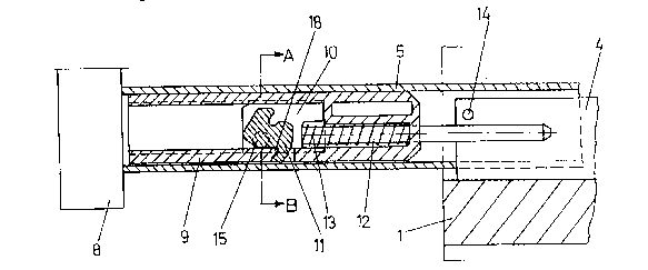
Figure 3 is a horizontal sectional view of an pull-out
rail and a part of the body of the furniture in the
region of the closing device with the drawer open.
Figure 4 is the same view with the drawer closed.
Figure 5 is a vertical sectional view of an pull-out
rail in the region of the closing device in a second
embodiment of the invention in the open position.
Figure 6 is an identical view as that of Figure 5 in
the closing position.
Figure 7 is a sectional view taken along line A-B of
Figure 3.
~ .
'

~ r~ ~ ;P3 /~3
Figure 8 is a sectional view taken along line E-F of
Figure 5.
Figure 9 is a cross sectional view of a drawer.
Figures 10 and 11 are exploded schematics of an
embodiment of the invention.
Figure 9 shows the essential parts of a drawer and a
drawer cabinet, the body side walls 1, the body bottom
6I the drawer bottom Z, the two drawer side walls 3 and
the pull-out rail 5 arranged in the lower region of the
drawer frames, the drawer backwall 7 and the support
rails 4 attached to the body side wall 1.
The pull-out rails S are attached to the drawer side
walls 3 in the conventional manner.
The closing device is arranged at the front end of each
pull-out rail 5. The important parts of the closing
device are the housing 9, 19, the pivoting lever 11,
21, the slide 10, 20, the spring 13, 25 and the guide
rod 12, 24. These parts are mounted on the drawer or on
the pull-out rail 5. The spring 13, 25 in the
embodiment is a pressure spring.

6 2~.3.'4.3~
A bolt 14 or 22 is located on the support rail 4.
In the embodiment according to Figures 3, 4 and 7 the
pivoting segment 11 can be rotated around a vertical
axis 15. The pivoting segment 11 exhibits a projection
27, which, when the closing device is put under stress,
locks in a recess 29 behind a bolt edge 18. This
situation is shown in Figure 3. In so doing, the drawer
is open. If the drawer is moved to the right, the
pivoting lever 11 remains in its position until it
strikes against the tang 14, which is attached to the
support rail 4. In this manner the pivoting lever 11 is
rotated counterclockwise and the projection 27 is moved
out of its locking position in recess 28. At this stage
the pressure spring 13 can move the slide 10 together
with the pivoting lever 11 relative to the housing 9 to
the left. However, it involves a relative movement,
i.e. the pivoting segment 11 is held with the slide 10
at tang 14 and the spring 13 pushes the housing 9 and
thus the entire drawer to the right into the furniture
body until the front panel 8 strikes against the face
of the body side walls 1.
If the drawer is opened, i.e. moved to the left from
the position shown in Figure 4, the position of slide

~ '.3~
10 and pivoting lever 11 remains unchanged until the
recess 28 is on a level with the projection 27. In so
doing, spring 13 is tightened. If the recess 18 reaches
projection 27, the pivoting segment is rotated
clockwise and the tang 14 is released.
At this stage the drawer can be pulled out freely
without having to overcome a spring force.
The embodiment according to Figures 5, 6 and 8 function
according to the same principle, only the pivoting
segment 21 is pivoted around a horizontal axis 26. The
pivoting segment 21 rests again on a straight line,
i.e. on a slide 20 that can be moved in a straight line
in the housing 19 and is loaded by a pressure spring
25. When the drawer is closed (Figure 6), the pressure
spring 25 is relaxed and the pivoting segment 21
encloses the tang 22, which is attached to the body
rail 4.
If the drawer is opened, the pivoting segment 21 and
slide 20 remain at tang 22, while the pressure spring
25' is tightened.
However, if the recess 28 is above the projection 27 of
the pivoting segment 21, the pivoting segment 21 is

8 x ~
rotated counterclockwise subject to the action of the
pressure spring, so that projection 27 projects into
the recess 28 located above said projection and strikes
against the bolt edge 23.
Tang 22 is thus released and the drawer can be pulled
out without any impedance.
When the drawer is closed, the same operation takes
place as in the case with the embodiment described
above, i.e. the pivoting segment 21 remains in the
position shown in Figure 5 until it reaches tang 22 in
the furniture body. If the drawer is pushed further
into the furniture body, the pivoting segment 21 is
rotated and the projection slides past the bold edge 23
out of the recess 28. At this stage the pressure spring
25 pushes the housing 19 and thus the pull-out rail 5
and the entire drawer into the body of the furniture.
Housing 9 or 19 can be provided with both projections
and snap into pull-out rail 5 in punch outs or also
exhibit recesses into which vice versa punched tongues
of the pull-out rail 5 lock again.
Of course, the pressure spring 25 can be braced at a
punched tongue of the pull-out rail 5 instead of at

2 ~J Lj ~ J 3
housing 9, 19. Similarly the guide rods 12, 24 can be
guided in such a tongue (see Figures 5, 6).

Representative Drawing
A single figure which represents the drawing illustrating the invention.
Administrative Status

2024-08-01:As part of the Next Generation Patents (NGP) transition, the Canadian Patents Database (CPD) now contains a more detailed Event History, which replicates the Event Log of our new back-office solution.

Please note that "Inactive:" events refers to events no longer in use in our new back-office solution.

For a clearer understanding of the status of the application/patent presented on this page, the site Disclaimer , as well as the definitions for Patent , Event History , Maintenance Fee  and Payment History  should be consulted.

Event History

Description Date
Inactive: IPC expired 2017-01-01
Inactive: IPC from MCD 2006-03-11
Application Not Reinstated by Deadline 2003-06-18
Inactive: Dead - Final fee not paid 2003-06-18
Deemed Abandoned - Failure to Respond to Maintenance Fee Notice 2002-07-30
Deemed Abandoned - Conditions for Grant Determined Not Compliant 2002-06-18
Notice of Allowance is Issued 2001-12-18
Letter Sent 2001-12-18
Inactive: Approved for allowance (AFA) 2001-11-29
Amendment Received - Voluntary Amendment 2001-08-15
Inactive: S.30(2) Rules - Examiner requisition 2001-04-20
Amendment Received - Voluntary Amendment 1999-04-07
Letter Sent 1998-08-17
Inactive: Status info is complete as of Log entry date 1998-08-17
Inactive: Application prosecuted on TS as of Log entry date 1998-08-17
Request for Examination Requirements Determined Compliant 1998-07-28
All Requirements for Examination Determined Compliant 1998-07-28
Application Published (Open to Public Inspection) 1992-02-01

Abandonment History

Abandonment Date Reason Reinstatement Date
2002-07-30
2002-06-18

Maintenance Fee

The last payment was received on 2001-07-06

Note : If the full payment has not been received on or before the date indicated, a further fee may be required which may be one of the following

  • the reinstatement fee;
  • the late payment fee; or
  • additional fee to reverse deemed expiry.

Please refer to the CIPO Patent Fees web page to see all current fee amounts.

Fee History

Fee Type Anniversary Year Due Date Paid Date
MF (application, 6th anniv.) - standard 06 1997-07-30 1997-06-19
MF (application, 7th anniv.) - standard 07 1998-07-30 1998-07-07
Request for examination - standard 1998-07-28
MF (application, 8th anniv.) - standard 08 1999-07-30 1999-07-06
MF (application, 9th anniv.) - standard 09 2000-07-31 2000-06-20
MF (application, 10th anniv.) - standard 10 2001-07-30 2001-07-06
Owners on Record

Note: Records showing the ownership history in alphabetical order.

Current Owners on Record
JULIUS BLUM GESELLSCHAFT M.B.H.
Past Owners on Record
ERICH ROCK
HELMUT HOLLENSTEIN
Past Owners that do not appear in the "Owners on Record" listing will appear in other documentation within the application.
Documents

To view selected files, please enter reCAPTCHA code :


To view images, click a link in the Document Description column. To download the documents, select one or more checkboxes in the first column and then click the "Download Selected in PDF format (Zip Archive)" or the "Download Selected as Single PDF" button.

List of published and non-published patent-specific documents on the CPD .

If you have any difficulty accessing content, you can call the Client Service Centre at 1-866-997-1936 or send them an e-mail at CIPO Client Service Centre.


Document
Description 
Date
(yyyy-mm-dd) 
Number of pages   Size of Image (KB) 
Representative drawing 1999-04-20 1 14
Drawings 1994-02-26 10 150
Cover Page 1994-02-26 1 12
Claims 1994-02-26 3 46
Description 1994-02-26 9 200
Abstract 1994-02-26 1 16
Claims 2001-08-15 10 332
Description 2001-08-15 13 386
Abstract 2001-08-15 1 16
Drawings 2001-08-15 10 152
Reminder - Request for Examination 1998-03-31 1 117
Acknowledgement of Request for Examination 1998-08-17 1 194
Commissioner's Notice - Application Found Allowable 2001-12-18 1 166
Courtesy - Abandonment Letter (Maintenance Fee) 2002-08-27 1 182
Courtesy - Abandonment Letter (NOA) 2002-08-27 1 170
Fees 1995-06-09 1 58
Fees 1996-06-21 1 54
Fees 1994-06-17 1 58
Fees 1993-07-12 1 36