Sélection de la langue

Search

Sommaire du brevet 2048153 

Énoncé de désistement de responsabilité concernant l'information provenant de tiers

Une partie des informations de ce site Web a été fournie par des sources externes. Le gouvernement du Canada n'assume aucune responsabilité concernant la précision, l'actualité ou la fiabilité des informations fournies par les sources externes. Les utilisateurs qui désirent employer cette information devraient consulter directement la source des informations. Le contenu fourni par les sources externes n'est pas assujetti aux exigences sur les langues officielles, la protection des renseignements personnels et l'accessibilité.

Disponibilité de l'Abrégé et des Revendications

L'apparition de différences dans le texte et l'image des Revendications et de l'Abrégé dépend du moment auquel le document est publié. Les textes des Revendications et de l'Abrégé sont affichés :

  • lorsque la demande peut être examinée par le public;
  • lorsque le brevet est émis (délivrance).
(12) Demande de brevet: (11) CA 2048153
(54) Titre français: MECANISME DE FERMETURE DE TIROIRS
(54) Titre anglais: A CLOSING MECHANISM FOR DRAWERS
Statut: Réputée abandonnée et au-delà du délai pour le rétablissement - en attente de la réponse à l’avis de communication rejetée
Données bibliographiques
(51) Classification internationale des brevets (CIB):
(72) Inventeurs :
  • ROCK, ERICH (Autriche)
  • HOLLENSTEIN, HELMUT (Autriche)
(73) Titulaires :
  • JULIUS BLUM GESELLSCHAFT M.B.H.
(71) Demandeurs :
  • JULIUS BLUM GESELLSCHAFT M.B.H. (Autriche)
(74) Agent: MARKS & CLERK
(74) Co-agent:
(45) Délivré:
(22) Date de dépôt: 1991-07-30
(41) Mise à la disponibilité du public: 1992-02-01
Requête d'examen: 1998-07-28
Licence disponible: S.O.
Cédé au domaine public: S.O.
(25) Langue des documents déposés: Anglais

Traité de coopération en matière de brevets (PCT): Non

(30) Données de priorité de la demande:
Numéro de la demande Pays / territoire Date
A 1607/90 (Autriche) 1990-07-31

Abrégés

Abrégé anglais


Abstract
A closing device for drawers. A pull-out rail (5)
attached to the drawer and a support rail (4) attached
to the body of the furniture are provided on each side
of the drawer. Load-transferring rollers are mounted
between the rails (4, 5). The closing device comprises
a pivoting segment (19, 21) that is subject to the
action of a spring and exhibits a receiving slot for a
tang (14, 22) mounted on the support rail (4). The
pivoting segment (19, 21) can be slid along pull-out
rail (5) in a straight line in the pull-out direction
of the drawer. Said pivoting segment (19, 21) is
mounted on a slide (10, 20), which is loaded by a
spring (12, 25).

Revendications

Note : Les revendications sont présentées dans la langue officielle dans laquelle elles ont été soumises.


THE EMBODIMENTS OF THE INVENTION IN WHICH EXCLUSIVE
PROPERTY OR PRIVILEGE IS CLAIMED ARE DEFINED AS FOLLOWS:
1. Closing device for drawers, where a pull-out rail
attached to the drawer and a support rail attached
to the body of the furniture are provided on each
side of the drawer and load-transferring rollers
or the like are mounted on or between the rails
and the closing device comprises a pivoting
segment subject to the action of a spring and a
tang catching in said pivoting segment, wherein
the pivoting segment (11, 21) is mounted on a
slide (10, 20), which is loaded by a spring (12,
25) and can be slid in a straight line in the
pull-out direction of the drawer.
2. Closing device, as claimed in claim 1, wherein the
tang (14, 22) is moulded or attached to the body-
sided support rail (4), whereas the slide (10, 20)
and the pivoting segment (11, 21) are mounted on
the drawer.
3. Closing device, as claimed in claim 1 and/or 2,
wherein the pivoting segment (11, 21), the slide
(10, 20) and the spring (13, 25) are mounted in a
housing (9, 19).

4. Closing device, as claimed in claim 3, wherein the
housing (9, 19) is attached to a pull-out rail
(5).
5. Closing device, as claimed in at least one of the
claims 1 to 4, wherein
the pivoting segment (11, 25) can be swivelled
around a vertical axis and the tang (14, 22) is
aligned vertically.
6. Closing device, as claimed in at least one of the
claims 1 to 5, wherein
the spring (13, 25) which is a pressure spring is
designed as a helical spring and mounted on a
guide rod (12, 24).
7. Closing device, as claimed in at least one of the
claims 1 to 6, wherein
the pivoting segment (11, 21) exhibits a
projection (27), which reaches into a recess (28)
in the housing (9) behind a bracket edge (18).
8. Closing device, as claimed in claim 3 and/or 4,
wherein the housing (9, 10) is mounted on the
front end of the pull-out rail (5).

9. Closing device as claimed in claim 4, wherein said
housing (9, 19) is mounted within the pull-out
rail profile.

Description

Note : Les descriptions sont présentées dans la langue officielle dans laquelle elles ont été soumises.

Closing device for drawers
The invention relates to a closing device for drawers,
where an pull-out rail attached to the drawewr and a
support rail attached to the body of the furniture are
provided on each side of the drawer and load-
transferring rollers or the like are mounted on or
- between the rails and the closing device comprises a
pivoting segment subject to the action of a spring an a
tang catching in said pivoting segment.
Modern drawers are provided with an extension guide
fitting, which comprises on both sides of the drawer a
body-sided support rail and a drawer-sided pull-out
rail and which is to make the sliding movement of the
drawer as easy as possible. To transfer the load
between the drawer-sided pull-out rails and the body-
sided support rails, rollers, spheres or also slides
I can be provided, depending on which requirements with
! 20 respect to the smoothness of running and load are
imposed on the drawer.
It has been demonstrated that in many cases closed
drawers are not moved completely into the rear terminal
position, that means into the body, and project with
their front panel from the body of the furniture. The

2 ~ ~'i3 .L ';~ 3
consequences thereof can be that someone bumps into the
drawer, a state that in turn can lead to an injury to
the person or damage to the drawer.
The protruding of the front pangel of the drawer from
the front of the furniture can result from the drawer
being pushed carelessly and not completely into the
body of the furnituxe. But even if the drawer was
pushed with too much energy into the body of the
furniture, the drawer can roll to the front again owing
to the excess energy.
A locking device for a drawer is known from the British
patent 1 117 071, in which a pivoting member that can
be moved between two terminal positions is provided.
The pivoting member is loading by a helical spring an
pushed into the respective terminal position by means
of said spiral spring after overcoming a dead point.
The pivoting member is attached to a side wall of the
furniture. The drawer has on the side wall a tang,
which in the terminal region of the travel way of the
drawer is moved into a slot in the pivoting member.
Finally, the tang pushes the pivoting member over a
dead point position, whereupon the pivoting member
itself pulls the tang and thus the drawer to the rear.

3 2~8~ 33
The object of the invention is to provide a closing
device in which the drawer is pulled over a longer
distance into the body. In so doing, the drawer is to
be pulled in as uniformly as possible. Another object
of the invention is to provide a closing device of this
kind that can be mounted on the drawer so as to save
space.
This is accomplished according to the invention in that
the pivoting segment is mounted on a slide, which is
loaded by a spring and can be slid in a straight line
in the pull-out direction of the drawer.
It is provided in an advantageous manner that the
pivoting segment, the slide and the spring are mounted
in a housing. Such a housing can be attached simply and
rapidly to the pull-out rail.
The housing is attached in an advantegeous manner to
¦ 20 the front end o-f an pull-out rail. In this manner, the
pivoting segment is readily accessible, should there be
a faulty pivoting. If the pull-out rail has a U-profile
of the like the housing is advantegeous mounted within
the profile of the rail.
:
i
. :: .. . . -
- . - :
'

4 '~ 8 i. ,~ ~
In the following two embodiments of the invention are
described with the aid of the figures of the
accompanying drawings.
Figure 1 is a side vie~ of a drawer with a closing
device according to the invention in the opening
position.
Figure 2 is a side view of the same drawer in the
closing position.
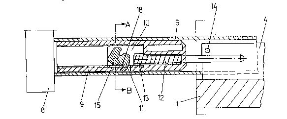
Figure 3 is a horizontal sectional view of an pull-out
rail and a part of the body of the furniture in the
region of the closing device with the drawer open.
Figure 4 is the same view with the drawer closed.
Figure 5 is a vertical sectional view of an pull-out
rail in the region of the closing device in a second
embodiment of the invention in the open position.
Figure 6 is an identical view as that of Figure 5 in
the closing position.
Figure 7 is a sectional view taken along line A-B of
Figure 3.
~ .
'

~ r~ ~ ;P3 /~3
Figure 8 is a sectional view taken along line E-F of
Figure 5.
Figure 9 is a cross sectional view of a drawer.
Figures 10 and 11 are exploded schematics of an
embodiment of the invention.
Figure 9 shows the essential parts of a drawer and a
drawer cabinet, the body side walls 1, the body bottom
6I the drawer bottom Z, the two drawer side walls 3 and
the pull-out rail 5 arranged in the lower region of the
drawer frames, the drawer backwall 7 and the support
rails 4 attached to the body side wall 1.
The pull-out rails S are attached to the drawer side
walls 3 in the conventional manner.
The closing device is arranged at the front end of each
pull-out rail 5. The important parts of the closing
device are the housing 9, 19, the pivoting lever 11,
21, the slide 10, 20, the spring 13, 25 and the guide
rod 12, 24. These parts are mounted on the drawer or on
the pull-out rail 5. The spring 13, 25 in the
embodiment is a pressure spring.

6 2~.3.'4.3~
A bolt 14 or 22 is located on the support rail 4.
In the embodiment according to Figures 3, 4 and 7 the
pivoting segment 11 can be rotated around a vertical
axis 15. The pivoting segment 11 exhibits a projection
27, which, when the closing device is put under stress,
locks in a recess 29 behind a bolt edge 18. This
situation is shown in Figure 3. In so doing, the drawer
is open. If the drawer is moved to the right, the
pivoting lever 11 remains in its position until it
strikes against the tang 14, which is attached to the
support rail 4. In this manner the pivoting lever 11 is
rotated counterclockwise and the projection 27 is moved
out of its locking position in recess 28. At this stage
the pressure spring 13 can move the slide 10 together
with the pivoting lever 11 relative to the housing 9 to
the left. However, it involves a relative movement,
i.e. the pivoting segment 11 is held with the slide 10
at tang 14 and the spring 13 pushes the housing 9 and
thus the entire drawer to the right into the furniture
body until the front panel 8 strikes against the face
of the body side walls 1.
If the drawer is opened, i.e. moved to the left from
the position shown in Figure 4, the position of slide

~ '.3~
10 and pivoting lever 11 remains unchanged until the
recess 28 is on a level with the projection 27. In so
doing, spring 13 is tightened. If the recess 18 reaches
projection 27, the pivoting segment is rotated
clockwise and the tang 14 is released.
At this stage the drawer can be pulled out freely
without having to overcome a spring force.
The embodiment according to Figures 5, 6 and 8 function
according to the same principle, only the pivoting
segment 21 is pivoted around a horizontal axis 26. The
pivoting segment 21 rests again on a straight line,
i.e. on a slide 20 that can be moved in a straight line
in the housing 19 and is loaded by a pressure spring
25. When the drawer is closed (Figure 6), the pressure
spring 25 is relaxed and the pivoting segment 21
encloses the tang 22, which is attached to the body
rail 4.
If the drawer is opened, the pivoting segment 21 and
slide 20 remain at tang 22, while the pressure spring
25' is tightened.
However, if the recess 28 is above the projection 27 of
the pivoting segment 21, the pivoting segment 21 is

8 x ~
rotated counterclockwise subject to the action of the
pressure spring, so that projection 27 projects into
the recess 28 located above said projection and strikes
against the bolt edge 23.
Tang 22 is thus released and the drawer can be pulled
out without any impedance.
When the drawer is closed, the same operation takes
place as in the case with the embodiment described
above, i.e. the pivoting segment 21 remains in the
position shown in Figure 5 until it reaches tang 22 in
the furniture body. If the drawer is pushed further
into the furniture body, the pivoting segment 21 is
rotated and the projection slides past the bold edge 23
out of the recess 28. At this stage the pressure spring
25 pushes the housing 19 and thus the pull-out rail 5
and the entire drawer into the body of the furniture.
Housing 9 or 19 can be provided with both projections
and snap into pull-out rail 5 in punch outs or also
exhibit recesses into which vice versa punched tongues
of the pull-out rail 5 lock again.
Of course, the pressure spring 25 can be braced at a
punched tongue of the pull-out rail 5 instead of at

2 ~J Lj ~ J 3
housing 9, 19. Similarly the guide rods 12, 24 can be
guided in such a tongue (see Figures 5, 6).

Dessin représentatif
Une figure unique qui représente un dessin illustrant l'invention.
États administratifs

2024-08-01 : Dans le cadre de la transition vers les Brevets de nouvelle génération (BNG), la base de données sur les brevets canadiens (BDBC) contient désormais un Historique d'événement plus détaillé, qui reproduit le Journal des événements de notre nouvelle solution interne.

Veuillez noter que les événements débutant par « Inactive : » se réfèrent à des événements qui ne sont plus utilisés dans notre nouvelle solution interne.

Pour une meilleure compréhension de l'état de la demande ou brevet qui figure sur cette page, la rubrique Mise en garde , et les descriptions de Brevet , Historique d'événement , Taxes périodiques et Historique des paiements devraient être consultées.

Historique d'événement

Description Date
Inactive : CIB expirée 2017-01-01
Inactive : CIB de MCD 2006-03-11
Demande non rétablie avant l'échéance 2003-06-18
Inactive : Morte - Taxe finale impayée 2003-06-18
Réputée abandonnée - omission de répondre à un avis sur les taxes pour le maintien en état 2002-07-30
Réputée abandonnée - les conditions pour l'octroi - jugée non conforme 2002-06-18
Un avis d'acceptation est envoyé 2001-12-18
Lettre envoyée 2001-12-18
Inactive : Approuvée aux fins d'acceptation (AFA) 2001-11-29
Modification reçue - modification volontaire 2001-08-15
Inactive : Dem. de l'examinateur par.30(2) Règles 2001-04-20
Modification reçue - modification volontaire 1999-04-07
Lettre envoyée 1998-08-17
Inactive : Renseign. sur l'état - Complets dès date d'ent. journ. 1998-08-17
Inactive : Dem. traitée sur TS dès date d'ent. journal 1998-08-17
Exigences pour une requête d'examen - jugée conforme 1998-07-28
Toutes les exigences pour l'examen - jugée conforme 1998-07-28
Demande publiée (accessible au public) 1992-02-01

Historique d'abandonnement

Date d'abandonnement Raison Date de rétablissement
2002-07-30
2002-06-18

Taxes périodiques

Le dernier paiement a été reçu le 2001-07-06

Avis : Si le paiement en totalité n'a pas été reçu au plus tard à la date indiquée, une taxe supplémentaire peut être imposée, soit une des taxes suivantes :

  • taxe de rétablissement ;
  • taxe pour paiement en souffrance ; ou
  • taxe additionnelle pour le renversement d'une péremption réputée.

Veuillez vous référer à la page web des taxes sur les brevets de l'OPIC pour voir tous les montants actuels des taxes.

Historique des taxes

Type de taxes Anniversaire Échéance Date payée
TM (demande, 6e anniv.) - générale 06 1997-07-30 1997-06-19
TM (demande, 7e anniv.) - générale 07 1998-07-30 1998-07-07
Requête d'examen - générale 1998-07-28
TM (demande, 8e anniv.) - générale 08 1999-07-30 1999-07-06
TM (demande, 9e anniv.) - générale 09 2000-07-31 2000-06-20
TM (demande, 10e anniv.) - générale 10 2001-07-30 2001-07-06
Titulaires au dossier

Les titulaires actuels et antérieures au dossier sont affichés en ordre alphabétique.

Titulaires actuels au dossier
JULIUS BLUM GESELLSCHAFT M.B.H.
Titulaires antérieures au dossier
ERICH ROCK
HELMUT HOLLENSTEIN
Les propriétaires antérieurs qui ne figurent pas dans la liste des « Propriétaires au dossier » apparaîtront dans d'autres documents au dossier.
Documents

Pour visionner les fichiers sélectionnés, entrer le code reCAPTCHA :


Pour visualiser une image, cliquer sur un lien dans la colonne description du document. Pour télécharger l'image (les images), cliquer l'une ou plusieurs cases à cocher dans la première colonne et ensuite cliquer sur le bouton "Télécharger sélection en format PDF (archive Zip)" ou le bouton "Télécharger sélection (en un fichier PDF fusionné)".

Liste des documents de brevet publiés et non publiés sur la BDBC .

Si vous avez des difficultés à accéder au contenu, veuillez communiquer avec le Centre de services à la clientèle au 1-866-997-1936, ou envoyer un courriel au Centre de service à la clientèle de l'OPIC.


Description du
Document 
Date
(aaaa-mm-jj) 
Nombre de pages   Taille de l'image (Ko) 
Dessin représentatif 1999-04-20 1 14
Dessins 1994-02-26 10 150
Page couverture 1994-02-26 1 12
Revendications 1994-02-26 3 46
Description 1994-02-26 9 200
Abrégé 1994-02-26 1 16
Revendications 2001-08-15 10 332
Description 2001-08-15 13 386
Abrégé 2001-08-15 1 16
Dessins 2001-08-15 10 152
Rappel - requête d'examen 1998-03-31 1 117
Accusé de réception de la requête d'examen 1998-08-17 1 194
Avis du commissaire - Demande jugée acceptable 2001-12-18 1 166
Courtoisie - Lettre d'abandon (taxe de maintien en état) 2002-08-27 1 182
Courtoisie - Lettre d'abandon (AA) 2002-08-27 1 170
Taxes 1995-06-09 1 58
Taxes 1996-06-21 1 54
Taxes 1994-06-17 1 58
Taxes 1993-07-12 1 36