Note: Descriptions are shown in the official language in which they were submitted.
2048319
FIELD OF INVENT~ON
This invention relates to paint brush receptacles adapted to accommodate paint brushes
and in particular relates to paint receptacles engageable with the peripheral inner edge
of an open paint can.
Background of the Invention
Persons who generally paint articles or buildings typically insert a paint brush into an
open paint can and scrape excess paint therefrom against the inner peripheral edge of
the open paint can. Such action usually results in spillage of paint into the rim
channel of the paint can m~king it difficulty and messy to close.
Furthermore, it becomes difficult for a user of an open paint can to grasp the handle
of an open paint can in one hand while holding a paint brush in either the same or
other hand while climbing a ladder.
Various devices have heretofore been devised in order to minimi7e the spillage of paint
onto the rim channel of a paint can as well as the transporting a paint brush.
For example, United States Patent No. 3,688,943 relates to a plastic ring provided at
its outer edge with a flange or other clamping mechanism to fit over and to attach
securely to the circular rim of an open paint can and includes a container which is
secured to the plastic rim by means of a hooking mechanism.
*
2 2048319
Moreover, United States Patent No. 4,094,431 illustrates an assembly comprising a paint
tray with a paint brush attachment for simultaneously accommo-l~ting both a paint
roller and a paint brush.
Yet another arrangement is shown in United States Patent No. 4,867,322 which relates
to a tool holder which holds tools within a container such as a 5 gallon bucket.
Yet another arrangement is shown in United States Patent No. 3,581,904 which relates
to a paint sieve having a top opening to receive a brush and adapted for variable
height attachment inside a paint bucket so that the sieve can be raised or lowered in
the bucket to remain partially emersed in the paint during painting.
Finally, United States Patent No. 4,765,472 illustrates a bucket attachment tool holder
for mounting on a conventional bucket having a loop handle.
These and other prior art devices present relatively complicated structure having limited
utility.
It is an object of this invention to provide an improved paint brush receptacle which
is easy to use and construct.
2048319
The btoadest aspeet of ~his invention rela~ to a paint bn~h 1~ ~t ~ ptet to engage the
peripheral edge of an open paint ~an comprisiDg: a l~ottom wall ~ ing n~st~dir~ wall
forma~ions termin~ti~ at an open ent for ~ i~ paint bnl~h~ d~erein; one of the wall
formations having an e~rt~ n proja;ting eA~.ioll~ outwardly lI-cr~fi~ -; a leg ~c~r.J;n~
from s~id e~t~nsi<?n and spaced from ~id one of the wall forl~ati~m~ for insertion into ~e
open can and re~ cahly eng~?l~le with ~e p~.iph~l edge of ~e open paiM can; a sc~er
extPn~lin~ exteriorly outwardly from siaid e~ "~ for gcraping paint off s~id paint brush into
said open paint can and reasonably en~e~le ~rith said pe~ipheral edge of said open paint
can and for insertion of a ~unlb bet~een said ~ leg and said back ~vall to stabilize
~e ,~ptacle whcn said ~ep~rl~ is separa~ed from ~id paint cdn; and sclapet e~tGn~
uul~dldly from said convex etge of said A~ S~ and beyond said cxtension for scrdping
paint off ~id paint brush into said open paint can; a peripheral edge plujeo~ g downwardly
from said botom wall in the region remote from said extension.
It is ano~er a~pecr of thic invention to provide a paint blush re~ph~le e~P~bte with Ihe
h~ l inner edge of an open paint can having a pc~i~hc~al inner and oub~r edge and rim
channel, said P~c~p~rle cG.~ ;sing; a bottom wall formq~iûn; a back wall~ frl~nt wall, ant
a pair of ~ide walls vertically ~ps~n~1ing ftom said bottom wall and t~rmin~in~ at an open
end for receivi~g ~e paint bn~ herein; an e~ n projecting horizontally e~cteriorly
outwa~dly from said back wall; a leg depending verticall~ downwardly f~om ~aid eYtpnci~n
and spaced from said back wall for inse~ion into ~aid open paint can and relr- tlly
en~able wi~ said peripheral inner edge of said open pa~nt can; a Ccra~er ed~e P~e.~lin~
vertically upwardly from ~aid e-l~tlcion for scraping paint off ~aid p~,int bru~h into said paint
~..
20~8319
can; said ~e~rncion overlapping said rim c~nn~l 80 as to present a ba~rier against paint
dripping in~D ~id nm cllqnn~l.
Descri~ion of t~e Drawin~s
These and other objects and features shall now be d~ il~ in relation to ~e following
drawings:
Figure 1 is a per~pective view of the paint brush reC~pt~rlP which is releasably securable tO
an open paint can.
Figure 2 is a bottom plan view of the paint bmsh receptacle.
Figure 3 is a top plan view of ~e paint brush l~c~5^1e releasably Fng~g-oable wi~ the
p~ he~ol edge of the paint bn~sh receptacle.
Figure 4 is a side elevational view of the paint CaD.
Pigure 5 is a çross s~tional vjew of the paint brush rer~p~-le taken along the lines 5-5 of
figure 2.
Figure 6 is a front ele~rational view of ~e paint brush [~I,~clc
2048319
s
Figure 1 i5 a back ele~ational ~iew of ~e paint bn~ 1 c~
Figu~e 8 iV? a C1U3~ ional ~r~ew of the paint brush ~ wi~ a c4ver.
DESCRn'llON OF lNVl~O~
Like parts have been given like numbers ~roughout ~e Figu~es.
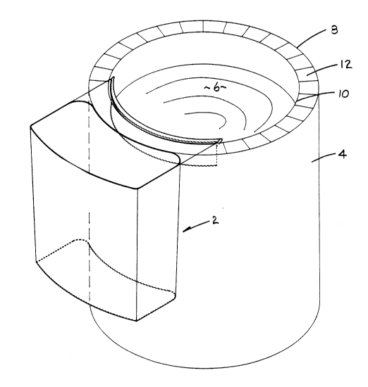
~'igure 1 ill~strates the pa~nt b~sh ~cept ~le 2 releasably secu~ed to open paint can 4.
The open paint can contains paint 6 and has an outer periphe}al edge 8, an inner pcriph~ld
edge 10, and a rim channel 12 fo~ rec~ption of a cover (not shown).
The paint brush recep~cle 2 may be comprised of a variety of materials including plastie
polypropylene and the like
The pain~ brush lcc~p~cle 2 includes a bottom ~?all 14 having a pair of spaced apart side
walls 16 and a fr~nt wall 18 and back wall 20~
l~e back, f~ont, and side walls 20? 18 and 16 r~?~livcly extend ver~ically upwardly from
the bottom wall 14 and terminate at an open end 22 for inser~ion of paint bnlshes or ~he like
within the confines of the ~ le 2.
~,
6 2048319
One of sait upstanting walls and in p~ rul~r tl~e bal;lc wall 20 ~ nl~ a hvli~ntz~lly
eYt~n~in~ e~ ion or annular ring portion 24 which E~r~jV :t~ ~AtLl;U.~Iy outwardly from
the back wall 20. The ~ 24 is c~4~-r~ 1 to ~e back wall 20 in the vicinity of ~he
open end 22 and tPnT~ at ~e o~er end thereof 90 a~ lo present a ~n~in~ leg 26 which
i~ af1~ to be inser~ into the interior of ~e open paint can 4.
The ~1epen~ leg 26 ~ep~nd~ vertically d~ ~ly from Lhe elcten~ n 24 Fur~h~ rG,
a scraper edge or lip 28 projects ~ertically upwardly from the extension 24 so as to present
a scraper edge 3rlapt~i to ~crape excess paint from a paint brush into the open paint can.
The p~nt brush rece~r~le 2 p~ ts a vertical up~t~m~ g ba~k wall 20 which has a cur~Gd
surface 30 a~apted to ool~forlll ~o and comact the outer surface of paint can 4. In parbcular~
the back wall 20 has a concave surface df~ign~d to contact and conror~ e outer surface of
the paint can 4.
The extension 24 has an annular horizonhl shape which is ada~ted to overly a por~on of the
rim 12 as best illustrate~l in figure 3 In particular, ~e ~ cion 24 l,le~n~s a barricr tn the
dripping of p~nt 6 into the rim c~ann~l 12.
The depending leg 26 prGs~rlls a space 32 within the c~llfin~s of the back wall 20~ r~
24 and leg 26 for a~:commrYl~tin~ the thumb of a u9et. ~n particular, ~e ~ tacle 20 may
be removed from the paint can ~ and a brush (not ghown) may be ir - ~d within the
re~eptacle 2 for p~i~tin~ of an article or wall or ~e like whe~eby the user would gr~sp ~e
recep~le 2 in a fashion so as to insert the thumb within the space 32 and the fingers would
~.
20~8319
grasp ~e front wall 18. Such use ~vould stabilize ~e receptacle 2 during use thereof when
s~pq~t~d from the paint ~an 4.
The front wall 18 al~o includes a convex surface and the oorners 40 of ~e rr~pt-~.e are
rounded so as to facilitate a ~,~lu.Lion ~ereof The tlt,p~ ¢ leg ~e~nls a convex surface
42 as best illustrated in figure 3 ~hich is adapted u~ contact ~e inner pc~ ;~hf 1~l edge 10 of
the Open paiM can 4 so as to ~ a~bly secu~ed or hang the t~ t~-cle 2 from ~e paint can
4.
The leg 26 depends vertically down~ardly from dle unterside of ~e extension 24 an~
presents a conve~c s~rfa~e which con~ctc the inner p~nphptal edge 10.
The scraper 28 projects outwardly from ~e upper surface of extension 24 and is also convex
shaped and ~ rt~l to ~c~e excess paint from a paint brush (not shown) back into the open
paint can 4 More particularly, the lip 28 extends outwartly from the eY~n~ion or angular
portion 24 so that the excess paint ~red again~t lip 28 drips back into the call ra~er than
.Yte~ion 24
1he ups~n~ling fronrl back, and sidL walls 18, 20 and 16 ~es~ively are tapered so as to
assist in the ctqrL-i~ lhcreof~
The paint btush recepta~le 2 as described herein pro~ides a place IO çar~y or slore the paim
bmsh (not shown) while t~n~ ing the open pail of paint 4. Mo~eover~ the paint brush
receptacle 2 provides the user with a place to wipe e~.cess paint while p7in~ingl as the
2o~83l9
unwan~ed or excess paint returns to the otiginal source for further use Mor~ r7 the paint
6 no longer collects in the rim 12 of ~he paint can 4 thus a~voiding spillage when ehe lid (not
shown) is put back onto ~e paint can 4.
Fu~ c~-~-ore, the paint brush receptacle 2 provides a hc~ti~n tD store a brush (not shown~
if p~inting is interrupted and ~e u~er pl~ns to cor~tim~ p~irlting in a reasonable ~o~mt of
time Mo~eo~er, the paint brush r~c~ ^le 2 provides the user with an area ro put ~e brush
into while the user is clilllbing a ladder or scaf~ lti so ~at the user will be able to manipulate
one l~nd t~ firmly grasp the mngs of the ladder or sc~ffol~-
The paint bmsh receptacle 2 can also be used to store a small amount of paint as a p~intin~source for doing louch up work as the c~n~t; shape as described above lends i~self to
sec~rely grasp the t~cept.lcle 2 by inserting the thumb into space 32. Mo~ r, ~e thumb
of the user into ~e space 3~ can be equally use~ by right or left handed ~r~ns
The paint brush receptacle 2 can also be u~ed to house a cl~nin~ solvent to completely clean
and soalc a brush once painting is completed or one can store a brush (once cle~ned) the~ein.
Fu~hermore, the rlimensioning of the paint brush ~ cle 2 facilities the ability to use 2
receptacles at one time on a paint can 4
Finally, ~e paillt brush receptacle can be used to slore additional bn~sh~s as different brushes
need to be used and can also be used to store water for la~:~ painting so that the brush is
already stL~ing while another brush is ~eing used.
3 1 ~
Figure 8 illllstrates a cover 50 which may be used in r~nn~ rion with the paint brush
rP~CePt CIP~ . The cover 50 is made of polypropylene and is timensioned ~o as to frictlolully
engage an ups~ndinf~ wall fc~ n~ l and includes two rLc~.~ring slots 52 and 54 which are
imPn~i~ nPd so as to fricti~ y engage and ~ecure bru~ ndl~ S6. Tlle cover can be used
in cases where it is desired to retain a brwll in ~ e 2 wi~ clP~nin~ sol~ent or ~e like.
The bottom wall 14 I,resell~ a pe~i~)h~al edge 70 pn~j~ting outwardly or downw~rdly from
dle ~ot~om wall 14 in tlle region remote from the extPnci~ln-
Although ~he pref~r,~ e~nbQ~1imAnt of the invention has been described herein, it would be~ppai~:nl to one sl~illed in the art The ~ariations may be made therero ~i~ deparring from
the spirit of the invention ot the scope of the ~ppen~l.oA claims.
4~i