Note: Descriptions are shown in the official language in which they were submitted.
2~8730
~ 1
"GROUND MARKER"
BACKGROUND OF THE INVENTION
This invention relates to a ground marker for
attachment to the ground or other support structure in a
manner which causes an elongate portion of the marker to
stand vertically upwardly from the ground.
Markers of this general type have previously been
proposed for marking the boundary of an area, an elongate
underground structure such as a pipeline, the edges of
bridges and other locations.
In some cases substantially rigid markers are used
but these have the severe disadvantage that as soon as they
are knocked or engaged by any passing vehicle, they are
immediately damaged usually beyond repair so that they need
to be regularly replaced.
There has therefore been an outstanding requirement
to provide a marker of a simple visible type which can be
easily mounted, inexpensive to manufacture and in addition is
sufficiently flexible so that it is not damaged when
impacted.
SUMMARY OF THE INVENTION
According to the first aspect of the invention
there is provided a ground marker comprising a elongate
substantially rigid plastic tube formed from a material which
renders the tube readily visible when supported in vertical
orientation upstanding from the ground and a support system
20~730
- 2 -
for holding the tube in a vertical orientation, the support
system comprising a cylindrical support member having the
tube received on an outer surface thereof coaxially
therewith, a helical coil spring, an attachment member
including a cylindrical support portion thereof, each of the
support member and support portion having a screw thread
formed along the outside surface thereof having a pitch
substantially equal to that of the springs so that respective
ends of the spring are engaged onto the end of the support
portion and the end of the support member to hold the support
portion and the support member in generally aligned position
with flexibility between the support portion and the support
member being provided by lateral flexing of the spring.
According to a second aspect of the invention there
is provided a ground marker comprising a elongate
substantially rigid plastic tube formed from a material which
renders the tube readily visible when supported in vertical
orientation upstanding from the ground and a support system
for holding the tube in a vertical orientation, the support
system comprising a cylindrical support member having the
tube received on an outer surface thereof coaxially
therewith, a helical coil spring, an attachment member
including a cylindrical support portion thereof, each of the
support member and support portion having a screw thread
formed along the outside surface thereof having a pitch
substantially equal to that of the springs so that respective
2~873~
- 3 -
ends of the spring are engaged onto the end of the support
portion and the end of the support member to hold the support
portion and the support member in generally aligned position
with flexibility between the support portion and the support
member being provided by lateral flexing of the spring, the
attachment member consisting solely of an elongate stake with
the support portion arranged at the upper end of the stake
and the lower end of the stake being sharpened for direct
driving into the ground, the support member and the stake
being formed from a length of pipe of constant outside
diameter, the length of the support member being less than
the length of the stake so as to extend into the tube over a
small proportion of the length of the tube, the lower end of
the stake be sharpened by the formation of a pinched section
by which the pipe is flattened from the lower end along a
short length of the pipe.
With the foregoing in view, and other advantages as
will become apparent to those skilled in the art to which
this invention relates as this specification proceeds, the
invention is herein described by reference to the
accompanying drawings forming a part hereof, which includes a
description of the best mode known to the applicant and of
the preferred typical embodiment of the principles of the
present invention, in which:
DESCRIPTION OF THE DRAWINGS
Figure 1 is a longitudinal cross sectional view
through a marker according to the present invention.
2B4~ ~3~
- 4 -
Figure 2 is an isometric view showing an
alternative embodiment of a marker according to the present
invention.
Figure 3 is a side elevational view of the stake
portion of the marker of Figure 1.
Figure 4 is a side elevational view of the holder
portion of Figure 1.
Figure 5 is a cross sectional view showing the
spring of Figure 1.
~10 Figure 6 is a side elevational view of the marker
tube of Figure 1.
Figure 7 is a side elevational veiw of a driver for
use in the assembly of the marker of Figure 1.
In the drawings like characters of reference
indicate corresponding parts in the different figures.
DETAILED DESCRIPTION
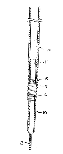
The marker of Figure 1 comprises a stake portion 10
and a holder 11 both of which are formed from a tubular pipe
by cutting to a required length with the stake portion being
longer than the holder portion. The stake portion has a
lowermost section thereof pinched to flatten the pipe as
indicated in Figures 1 and 3 to form a sharpened edge for
driving the stake portion into the ground.
Each of the portions has a screw thread section cut
into the outside surface and extending over a length of one
end of the portion of the order of 3/4 inch and indicated at
2~8730
- 5 -
12 and 13 respectively. The pitch of the screw thread is
equal to the pitch of a spring 15 which can thus be threaded
onto the screw thread section simply by rotating by hand
since the direction of rotation tends to open the spring and
allow it to thread freely onto the screw thread. The screw
thread is cut with circular groove shape to receive the
circular edges of the spring. The holder portion 11 receives
as a sliding fit on the outside surface thereof a vertical
marker tube 16 which is formed of a rigid plastics material.
The tube 16 slides down over the holder to a position
adjacent the upper edge of the spring. The marker tube is
thus substantially rigid and flexibility for the structure is
provided by a flexing of the spring in a lateral direction
that is by opening up one side of the spring as the axis of
the holder is pivoted about a line transverse to the spring.
the marker tube is sufficiently rigid that when impacted the
flexibility occurs at the spring rather than any flexing of
the marker tube.
Once assembled together the spring cannot simply be
extracted from the threaded sections of the stake and holder
due to the characteristics of the spring which tend to
tighten it onto the screw thread section. The plastic tube
is sized so that it presses onto the holder but cannot be
removed by hand. On the plastic tube can be provided pieces
of reflective tape that can be put on in various designs so
the marker is particularly visible at night. The marker tube
2~873V
- 6 -
is formed from plastics material because it is lighter than
the metal pipe and since it is a able to flex slightly upon
impact without the danger of ~orming a permanent bend. It
can also be made of different colors and sizes to provide a
particular marker effect when standing vertically upwardly
from the ground.
The driver of Figure 7 comprises an elongate body
having an annular channel 20 formed at one end extending from
the end into the body of the driver. In use therefore the
annular channel is placed over the screw thread portion 12 at
the stake 10 and the upper end of the driver defines an
abutment surface 21 for receiving blows from an impact tool
to drive the stake into the ground by way of the sharpened or
pinched end 22. The dimensions are shown in the drawings are
of course exemplary only but it will be noted that the holder
is just sufficient in length to provide the screw thread
section and also a sufficient length to receive the tube
without danger of the tube being twisted away from its
position around the exposed approximately five inch length of
the holder. The stake is of sufficient length to drive into
the ground leaving the screw thread portion just above the
ground and it has been found that the twenty-four inches
shown is a reasonable compromise length which is likely to be
driven into the groun~ without ~if~icultly but leaves the
marker sufficiently resistant to damage from impact with
vehicles or animals such as cattle.
2~873~
- 7 -
In Figure 2 is shown a modified arrangement in
which the attachment member for supporting the spring 15, the
holder 11 and the tube 16 is modified for attachment by way
of a bracket system to an existing structure. In this case
the attachment member generally indicated at 30 includes a
base plate 31 welded to a lower end of a support portion 32
of the upper end of which is formed the screw thread. The
base plate 31 includes apertures 33 by which it can be screw
fastened to a support structure such as a bridge or other
element.
Since various modifications can be made in our
invention as hereinabove described, and many apparently
widely different embodiments of same made within the spirit
and scope of the claims without departing from such spirit
and scope, it is intended that all matter contained in the
accompanying specification shall be interpreted as
illustrative only and not in a limiting sense.