Note: Descriptions are shown in the official language in which they were submitted.
W -1376
POWER TRANSUISSION V-BELT ~ ~ $~
Backqround of the Invention
Field of the Invention
This invention relates to power transmission V-belts
and, more particularly, to a belt that is particularly
adaptable for use with stepless speed variation pulleys
and which is constructed to resist a) side face and
tensile/load-carrying cord degr~dation, b) peeling of
adjacent layers, and c) fly out of the load-carrying
cords by reason of the outer portion of the drive/driven
side faces being forcibly engaged by cooperating pulley
parts during operation.
Back~round Art
V-belts are constructed with laterally oppositely
facing drive/driven faces which effect pulley rotation
utilizing a wedging action between the belt and
cooperating pulley surfaces. The lateral pressure on the
belt side faces may be very substantial during operation,
particularly in speed variable systems. Normally, V~
belts used in speed variable systems are constructed with
wide outside surfaces to resist this high lateral
pressure.
It is also known, to rigidify such V-belts in the
lateral direction, to employ a STIFLEX~ layer having
short staple reinforcing fibers embedded therein and
oriented in generally a lateral direction in that portion
of the belt that is the most heavily compressed by the
pulley parts. .Nonetheless, such belts, over time, become
substantially deformed as they are engaged by the speed
variation pulleys. This deformation may occur early in
the belt life in systems in which the pulley parts
~ W -1376
2 o ~ 8 g h ~
repetitively squeeze and release the side faces of th`e
belt during normal operation.
Aside from the problem of belt deformation, V-belts
used in speed variation pulley systems are prone to
cracXing, particularly at the outside region of the belt.
A further problem is that the pulleys, by severely
squeezing the outside region of the side faces of the V-
belt, tend to effect fly-out of the load-carrying cords
from the belt rubber layer in which they are embedded
and/or peeling of the rubber layer, in which the load-
carrying cords are embedded, from an adjacent layer.
A still further problem with the prior art belts is
that the repeated opening and closing of the pulley
pieces, defining the variable speed pulley, may result in
premature and excessive wear on the side faces of the
belt. For example, as the pulley pieces move closer
together to increase the effective diameter of the
pulley, the side surfaces are squeezed with a force
substantial enough to wedge the belt outwardly, which
causes considerable frictional wear on the belt side
faces. Eventually, the wear becomes significant enough
that the effective width of the belt is decreased which
results in a change in the speed variation ratio.
Consequently, over time, the operation of the overall
system, in which the belt operates, changes and becomes
unpredictable.
To eliminate the above problems, the assignee of the
present invention devised a speed variation V-belt, as
disclosed in Japanese Patent Laid-Open No. 164840/1989.
As shown in that publication, at least one, and
preferably a plurality, of sheets/layers of reed cord
screen-like material are provided with the reed cords
extending substantially parallel to each other and
laterally of the belt.
A
,~
~ ' `
W -1376
3 2 ~
The structure shown in Japanese Patent Laid-Open No~
164840/1989 is a cogged belt with longitudinally spaced
cogs/teeth and U-shaped valleys between adjacent
cogs/teeth formed from HRH-compound rubber. Load-
carrying cords are embedded in an adhesive rubber layer.
One reed cord screen-like sheet/layer is embedded in the
compression section of the belt so as to bisect the
distance between the load-carrying cords and the base of
the valleys. The reed cord screen-like sheet/layer
assumes a wave-like pattern during manufacture to
generally follow the contour of the cogs/teeth. It is
preferred that the thickness of the reed cords be in the
range of 0.20 to 0.45 times as large as the distance
between the bottom edge of the load-carrying cords and
the base of the valleyO A canvas layer is placed on the
inside and/or outside rubber surfaces of the belt.
While the above belt construction has proven very
successful, there nave been two associated problems. The
first is a result of the method of manufacturing the
~o cogged belt. The cogged belt is manufactured by first
forming the cogs/teeth and then vulcanizing the belt. In
forming the cogs/teeth, the reed cord screen-like
sheet/layer is bent in a wave form to generally follow
the cog/tooth shape. During belt formation, the adhesive
rubber layer tends to gather at the cogged portion of the
belt. The result of this may be that the reed cords come
into direct contact with the load-carrying cords in the
vicinity of the valleys. This problem is aggravated by
the thinness of th~ adhesive rubber layer. The result of
this is that, during operation, the engaged load-carrying
and reed corcls tend to abrade each other, which may
ultimately cause rupture of the load-carrying cord(s) and
thereby reduce the belt capacity.
The second problem is that the lateral pressure
exerted by the pulleys on the side faces of the V-belt
A#
~ 4 20~ 8 ~ :~
causes belt deformation, particularly at the outer
portion of the belt. Aside from the deformation that
occurs, there is a tendency of a) the adjacent belt
layers to peel and, more particularly, for the adhesive
layer with the load-carrying cords to peel from the
remainder of the belt and b) the load-carrying cords to
"fly out" of the rubber layer in which they are embedded.
These problems are attributable to the fact that the reed
cords are substantially rigid and the adhesive rubber
layer is relatively flexible in the lateral direction.
As the belt deforms under the forces produced by the
pulleys, the reed cords remain relatively stationary and
the adhesive layer bends and tends to be peeled back
towards the middle of the belt. This may release the
load-carrying cords from the rubber layer in which they
are embedded and/or separate the rubber layer in which
the load-carrying cords are embedded from an adjacent
layer. This problem is aggravated in environments in
which the deformation is repetitive during system
operation.
Summary of the Invention
The present invention is specifically directed to
overcoming the above-enumerated problems in a novel and
simple manner.
The present invention seeks to provide a power
transmission V-belt in which cogs/teeth can be formed by
conventional techniques without causing direct contact
~, between reed cords in a screen-like sheet/layer and
tensile/load carrying-cords, even using a relatively thin
adhesive layer in which the load-carrying cords are
embedded.
Further, the present invention seeks to a) prevent
the load-carrying cords from pulling out of the
adhesive layer in which they are embedded and b)
A~
,:
~,
` VU-1376
5 2~ g~
prevents the adhesive layer from separating from the reèd
cords/compression section rubber layer under severe belt
deformation.
More particularly, to achieve the above objectives,
the present invention contemplates a power transmission
V-belt having a plurality of longitudinally extending
load-carrying/tansile cords embedded in an adhesive
rubber layer, a compression section having a plurality of
laterally extending cords embedded in a second rubber
layer, and a reinforcing rubber layer interposed between
the adhesive rubber layer and the laterally extending
cords.
The reinforcing rubber layer serves as a spacer
between the laterally extending cords and the load-
carrying cords.
Additionally, the reinforcing rubber layer reduces
the otherwise extreme di~ference of lateral resistance
between the adhesive rubber layer and cords which could
precipitate tensile cord fly-out and/or separation
between the adhesive rubber layer and the lateral cords
and/or compression section rubber.
A highly durable belt is produced which is
particularly adaptable to systems employing stepless
speed variation pulleys.
In order to avoid the extreme difference of lateral
resistance in different parts of the belt, the
reinforcing rubber layer is rigidified in the lateral
direction by short staple fibers extending in the lateral
direction. The invention contemplates the provision of
short staple reinforcing fibers in the adhesive rubber
layer as well, however greater rigidity in the lateral
direction i5 afforded by providing a greater weight
percentage of fibers in the reinforcing rubber layer than
in the adhesive rubber layer.
,
A
~ W -1376
`: 2 ~ 8
Preferably, the reinforcing fibers are present i~
the reinforcing rubber layer in an amount of between 5-35
weight parts to 100 weight parts of rubber. The weight
percent of the reinforcing fibers in the compression
rubber layer is from 0-30% greater than the weight
percent of reinforcing fibers in the reinforcing rubber
layer.
In a preferred form, the aspect ratio of the ;
reinforcing fibers in the reinforcing rubber layer and
adhesive rubber layer is hetween 50 and 2,000. The
invention contemplates that the short staple reinforcing
fibers are made from at least one of: a) inorganic fiber
that is a natural fiber of one of cotton and pulp; b)
synthetic fiber that is one of nylon, polyester, aramid
and carbon fiber; and c) semisynthetic fiber that is one
of artificial silk and rayon.
Preferably, the reinforcing rubber layer has a ~-
thickness of between .2 and 5 mm. -
In one form of the invention, the laterally
extending cords are reed cords that are part of a screen- -
like sheet/layer.
The cords are preferably located in a range of .05
to .8 W from the inside edges of the load-carrying cords,
where W is equal to the distance between the inside edges
of the load-carrying cords and the inside surface of the
V-belt. In cogged belts, W is equal to the distance
between the inside edges of the load-carrying cords and
the inside surface of the valley between adjacent
cogs/teeth at the point therein closest to the load~
carrying cords.
Preferably, the cords are made from at least one of
polyester, aliphatic polyamide, aromatic polyamide, glass
fiber and carbon fiber. ;~
In one form, the adhesive rubber layer is at least
one of NR, SBR, CR and NBR. The invention contemplates
A
r~
.. ~ ;.
W -1376
7 2 ~ 3, ~
that the compression section rubber and reinforcin'g
rubber layer be made of the same material as the adhesive
rubber layer.
Brief Description of the Drawinqs
Fig. 1 is a perspective view of a cogged V-belt
ac~ording to the present invention;
Fig. 2 is an enlarged, side elevation view of the V-
belt in Fig. l;
Fig. 3 is a plan view of a reed cord screen-like
sheet/layer that is part of the inventive belt of Figs.
1 and 2;
Fig. 4 is a cross-sectional view of the inventive
belt taken along line 4-4 of Fig. l;
Fig. 5 is a side elevation view of a prior art
cogged V-belt;
Fig. 6 is a cross-sectional view of the prior art
belt taken along line 6-6 of Fig. 5; and
Fig. 7 is a graph of belt running time versus
variation in the distance between the shafts of pulleys
for both the inventive and prior art belts.
Detailed Description of the Drawin~s
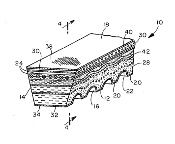
In Figs. 1-4, a cogged power transmission V-belt,
according to the present invention, is shown at 10.
While the belt configuration shown in Figs. 1-4 is
exemplary of one type of belt that is suitable for
incorporation of the present invention~ this disclosure
should not be viewed as limiting the invention to this
belt type. As a general matter, the invention is
intended to be;incorporated into V-belts of the raw-edged
type, whether a cogged V-belt, an REV belt, or the like.
The invention is particularly adaptable to belts having
a wider upper surface than the height of the belt, which
A
` W -1376
8 2 ~
-. .
belts are typically used with stepless speed variatio~
pulleys.
More particularly, ~he belt lO has a V-shaped cross
section defining raw, inclined, laterally oppositely
facing side faces 12, 14 for engagement with a pulley
(not shown). The belt lO has oppositely facing inside
and outside surfaces 16, 18, respectively. The inside of
the belt lO has a plurality of cogs/teeth 20 of a
predetermined pitch with there being valleys 22 between
adjacent cogs/teeth 20. The cogs/teeth 20 are configured
to mate in grooves in a cooperating pulley (not shown)
for the belt to effect driving thereof and be driven
thereby.
The belt lO has a plurality of lengthwise, load~
carrying/tensile cords 24 defining a neutral axis for the
belt lO. The load-carrying cords 24 are made of a
material with low elongation and high strength. Suitable
materials for the load-carrying cords 24 are at least one
of polyester, aliphatic polyamide, aromatic polyamide
(trade name KEVLAR~), glass fibers, etc.
The cords 24 are embedded in an adhesive rubber
layer 26. The adhesive rubber layer 26 is preferably made
from one of the following materials, or a blend thereof~
NR, SBR, CR, NBR, etc.
A compression section 28 is defined inside of the
load-carrying cords 24 with a tension section 30 being
defined outside of the cords 24. The rubber in the
tension section 30 is preferably the same rubber as that
used in the adhesive rubber layer 26 and in the
compression section 28.
A canvas layer 32 is adhered to the innermost rubber
surface 34 of the compression section 28. A canvas layer
38 is adhered to the outermost surface 40 of the rubber
defining the tension section 30. Preferably, l to 3
canvas layers 38 are provided on the surface 40. The
A
,!, . `
VU-1376
' 9 2~aL~ 3
canvas layer(s) 38 is preferably one of a bias canvas~
wide ar.gle canvas made of warp and weft cotton yarns, and
stretchable rubber-coated canvas. The rubber-coated
canvas is preferably wooly processed nylon with crimped
nylon or SPANDEX~ ~elastomeric yarn) warp yarns and
normal nylon weft yarns. The layers 38 are adhered by
methods known to those skilled in the art. One or a
plurality of layers of stretchable rubber-coated canvas,
such as that described for the canvas layer(s) 38, is
used to cover the outermost rubber surface 40.
The invention contemplates the provision of a
reinforcing rubber layer 42, made of one of the same
materials noted above for the rubber in the adhesive
rubber layer 26, compression section 28, and tension
section 30. The reinforcing rubber layer 42 preferably
has a thickness of between 0.2 to 5.0 mm.
The invention further contemplates the provision of
short staple reinforcing fibers 44 in the rubber in each
of the adhesive rubber layer 26, compression section 28,
and tension section 30 and oriented in a lateral
direction. The amount of the fibers 44 in each of the
adhesive rubber layer 26 and compression section 28 is
different so that the composition and effective hardness
of the adhesive rubber layer 26 and compression section
28 is different, for reasons described below.
The short staple reinforcing fibers 44 preferably
have an aspect ratio of 50 to 2,000 and are made of fiber
that is one of: a) inorganic fiber, such as natural fiber
cotton, pulp, etc.; b) synthetic fiber such as nylon,
polyester, aramid, carbon fiber, etc.; or c)
semisynthetic fiber such as artificial silk, rayon, etc.
In the adhesive rubber layer 26, 1 to 25 weight
parts of short staple reinforcing -fibers 44 is provided
to 100 weight parts of rubber. If more than the above-
specified amount of reinforcing fibers 44 is mixed in the
- . i . :,
` W -1376
,,, 10
adhesive rubber layer 26, the fibers 44 will prevent thè
load-carrying cords 24 from effectively adhering to the
adhesive rubber in which it is embedded. The result is
that the life of the belt is shortened. The load~
carrying cords 24 have a tendency to peel away from the
adhesive rubber layer 26 and "fly out".
Because the adhesive rubber layer 26 above the load-
carrying cords 24 is in tension, and the portion of the
adhesive rubber layer 26 below the load-carrying cords 24
is in compression, it is preferred that a lesser amount
of short staple reinforcing fibers 44 be embedded in the
adhesive rubber layer 26 above the load-carrying cords 24
than below the load-carrying cords 24.
An excess amount of short staple reinforcing fibers
44 in the adhesive rubber layer 26 also weakens that
rubber. Additionally, with excessive amounts of fibers
44, relative movement is allowed to occur between the
load-carrying cords 24 and fibers 44. In addition to
deteriorating the bond between the load-carrying cords 24
and adhesive rubber layer 26, this relative movement
produces friction which develops heat and wear on the
load-carrying cords 24, which may precipitate their
premature failure.
In the reinforcing rubber layer 42, 5 to 35 weight
parts of short staple reinforcing fiber 44, with the same
aspect ratio and composition as the fibers 44 in the
adhesive layer 26, are mixed with every 100 weight parts
of rubber in the reinforcing rubber layer 42. The amount
of reinforcing fibers 44 in the reinforcing rubber layer
42 is preferably always greater than that in the adhesive
rubber layer 26.
The compression section 28 has fibers 44 dispersed
therein with the same composition as the fibers 44 in the
adhesive layer 26, however, the weight percent of fibers
44 in the compression section 28 is O to 30% greater than
A~
W ~1376
11 2~ 2~
the weight percent of fibers 44 in the rein~orcing rubbe~
layer 42.
It is important that the ratio of fibers 44 be
controlled so that there is not a large variation in the
ratio of elasticity between t:he load-carrying cords 24
and adhesive rubber layer 26. Excessive variation could
result in peeling of the load-carrying cords 24 from the
adhesive rubber layer 26 and/or peeling of the layer 25
due to the stress concentration at the interface of the
belt parts having radically di$ferent elasticity in a
lateral direction.
The invention contemplates the incorporation of
layers of reed cord screen-like sheets/layers, as shown
at 46 in Fig. 3. The sheets/layers 46 consist of a
plurality of equidistantly spaced cords 48 held together
by yarns 50, adhesively bonded thereto to define a
unitary structure.
one or more layers ~one shown) of reed cord screen-
like sheets/layers 46 are embedded in the tension section
30 of the belt 10 so that the cords 48 extend in a
lateral direction. The cords 48 are preferably made of
one of polyester, aliphatic polyamide, aromatic
polyamide, glass fiber, carbon fiber, etc.
Two layers of reed cord screen-like sheets/layers
46', 46'' are embedded in the compression section 28 of
the belt 10. A single layer or more than two layers of
the reed cord screen-like sheet/layer 46, 46', 46'l could
be employed. The layers 46', 46'' are arranged in a
wave-like pattern to generally follow the contour of the
cogs/teeth 20 and are sufficiently long to be exposed at
both side faces 12, 14 of the belt 10.
The position of the layers 46', 46'' is in the range
of .05 to .8 W from the lower edge 50 of the load-
carrying cords 24, where W is the thickness of the belt
10 from the lower edge 50 of the load-carrying cords 24,
".,~
A
. ... ..
.....
. . ., -.~,
W -1376
12 2 ~
, . . .
i.e. the distance between the lower edge 50 of the load-
carrying cords 2~ and the base 52 of the valleys 22
between adjacent cogs/teeth 20. The reinforcing rubber
layer 42 resides between the load-carrying cords 24 and
the outermost layer 4~'.
Through experimentation, it has been found that if
either layer 46', 46 " is less than .05 W from the lower
cord edges 50, the thicXness of the reinforcing rubber
layer 42 is reduced to the point that it cannot
effectively prevent the a~orementioned peeling
phenomenon: that is the peeling of the adhesive rubber
layer 26 from the layer 46' and/or the compression
section 28. On the other hand, if either sheet/layer
46', 46'' is more than .8 W from the lower edge 50 of the
load-carrying cords 24, the sheets/layers 46', 46 "
locate too close to the botto~ of the cogs/teeth 20 to
reduce the flexibility of the belt 10. This might cause
the development of cracks in the compression section 28,
particularly in the thin belt section at the valleys 22.
Since the cords 48 in the layers 46', 46" extend
laterally and in parallel relationship, there is nothing
to inhibit the propagation of a crack in the lateral
direction.
It can be seen that with the present invention, the
interposing of the reinforcing rubber layer 42 between --
the adhesive rubber layer 26 and layer 46' eases the
concentration of stress between the adhesive rubber layer
26 and layers 46', 46 " . Compared with the adhesive
rubber layerj the reinforcing rubber layer is mor rigid
and effectively harder by reason of the rubher containing
0-30% more reinforcing fibers.
The reinforcing rubber layer 42 between the adhesive
rubber layer 26 and layers 46', 46'' serves the
additional function of preventing the cords 48 on the
sheets/layers 46', 46 " from contacting the load-carrying
A
W -1376
13 2 ~
cords 24 at the time of vulcanizing and molding of the
belt. This prevents detriment:al abrasion, each of the
other, as the belt 10 is flexed in use. This abrasion
could ultimately result in rupture of the load-carrying
cords 24 which diminishes belt performance.
The durability of the inventive belt i5 demonstrated
by the results of experimentation carried out by the
assignee herein.
The Inventive Test Belt
A cogged V-belt, according to the present invention,
having an outside surface 18 with a 38 mm width, 13 mm of
thickness and 1,100 mm of peripheral length was tested.
Two layers of reed cord screen-like sheets were embedded
in the compression section with the layer 46' .2 W and
layer 46 " .5 W from the lower edge 50 of the load-
carrying cords 24. A reinforcing rubber layer 42 was
provided between the adhesive rubber layer 26 and the
layer 46'.
The Conventional Test Belt
A conventional belt of the same shape as the above-
described inventive belt 10 was tested. This belt 60 is
shown in Figs. 5 and 6. The belt 60 had two reed cord
screen-like sheets/layers 62, 64 below the load-carrying
cords 66. The sheet/layer 62 was spaced from the bottom
edge 68 of the load-carrying cords 66 at .03 W, with the
innermost layer 64 spaced at .4 W from the bottom edge 68
of the load-carrying cords 66. No reinforcing rubber
layer was employed according to the invention.
''," '','~ ','''"'`
: ..:: ~. ~ .
L ~ : .:~.. :
~ . . .: :
"~ ,"" '" . '..`' '' ,:
':" .''`' ' :: ', ,"' '~
..`'~, .,~ ;.,':
W -1376
14 2~
,
Test Set-Up
The two belts were engaged with drive pulleys having
a diameter of 110 mm and driven pulleys having a diameter
of 225 mm. The belts were run under operating conditions
of a 270 kg dead weight with 5 ps of load and a rotating
speed of 1800 rpm. The lapse of running time and
variations in distances between the shafts on the pulleys
were measured to develop the data shown on the graph of
Fig. 7. The time at which trouble/failure occurred and
the nature of that trouble/failure was noted, with the
results identified in the following Table 1.
TABLE 1
= ~,".,""".",",.. , , j- ,,...... _ ,.,__
INVENTIVE BELTCONVENTIONAL BELT
~ . ~:
Reinforcing Yes No
Rubber Layer
.
Trouble 34 hrs. 15 hrs.
Occurring Time _ _
Trouble Separation between Fly-out of load-
occurring load-carrying carrying cord ~ -
Phenomenon cords and adhesive from adhesive
rubber layer rubber layer
.,. . "~__ _____ _ , , , ., . , ~,,,,...,...,. , ~ .. ~ .,
From the above, it can be seen that the running time
o~ the inventive belt up to the time the trouble occurred
was approximately twice as long as with the conventional -~
belt. When the conventional belt failed, the nature of
Z5 the failure was fly-out of the load-carrying cords. The
failure of the inventive belt, which was less severe, was
mere separation between the load-carrying cords and the
~adhesive rubber layer. As to the separation at the
boundary of the compression rubber layer and the adhesive
rubber layer, the inventive belt was more intact as
observed from the outside of the belt.
A
VU-1376
15 2 ~ 8~
In Fig. 6, the deformation of the belt 60 th~t
results in peeling and load-carrying cord fly-out can be
seen with respect to the conventional belt 60. As shown
in phantom lines, the corner 70 of the belt 60 is bent
considerably when compressed between the pulleys of a
variable speed pulley system.
As seen in the graph in Fig. 7, the line of the
conventional belt rises abrupt:ly when 4 mm of elongation
occurred between the shafts of the pulleys after 15 hours
of running time elapsed. Load-carrying cord fly-out
occurred at this time and the deformation of the belt was
increased. It was concluded that the distance between
the shafts of the pulleys was abruptly lengthened by the
direct influence of the dead weight.
The foregoing disclosure of specific embodiments is
intended to be illustrative of the broad concepts
comprehended by the invention.
~.,, , -. .
," "~ '
'.,'.'. :.~:.
, ~,.,,.-
A ~...... ` . -
.,, . ~ . ~ .. ..
,.. ., ~ .