Note: Descriptions are shown in the official language in which they were submitted.
2~87~3
IMPROVEMENT IN ROTARY GRINDER
The present invention relates to an improvement in
apparatuses for grinding solid mineral into fine
particles. Particularly, the invention relates to
lining the inner surface of the grinder chamber of a
grinder-classifier apparatus with resilient material
such that the grinding is done by colliding the
mineral against itself.
Rotary grinder-classifiers for grinding solid mineral
into a fine powder or particles generally function by
forcing the mineral to be ground on the outer wall of
~ a grinding chamber by the fast rotation of hammers.
;~ 15 It has usually been understood with this type of
grinders, whether the axis of rotation is vertical
or horizontal, that the grinding action is done by
the friction of the mineral between the metal wall
and thé hammers.~However, since these grinders are
all made of metal, the outer wall and hammers wear
: ou~ rather rapidly.
It hae now surprisingly been found~that a better and
faster~gr~inding can be achleved by lining the inner
25 surface o:E the o uter wall with a resilient material~
such~that~ the~ solid~ mineral does not fragmPnt upon
e ~ r ~ t ~ ~_ne~ ~po~ hittl:~
, ,
~,: . . .
.
.- . .
- ,,
: : - ~ . . , , .: - - . .
2 ~ 7 9
similar mineral after bounci~g from the wall.
Therefore, the present invention provides a rotary
grinder-classifier for grinding solid mineral into
fine par~icles, the grinder comprising a grinding
chamber comprising inlet means, outlet means, and an
outer ring having an inner surface,
a rotor rotating around a central axle .for driving a
plurality of hammers, these hammers forcing the
mineral.against the ring, where the inner surface of
the outer ring is lined with resilient material, in
such a manner that the mineral bounces off against
other mineral upon hitting the lined surface, thereby
facilitating the grinding.
In drawings which illustrate 0xamples of embodiments
. ~
~; of:the lnvention:
Figure 1 lS a~broken-away top plan view of a grinder
according to the lnvention;
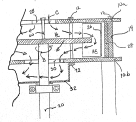
Figure 2 is~a broken-away cross-section view of the
grinder: portion of a grinder-classifier of figure 1
when~out along~llnes 2-2.
; 25
~: ~ ': :
~ ~ .
- ::
- . . ,
~8~
DETAILED DESCRIPTION OF EXAMPLES OF PREFERRED
EMBODIMENTS OF THE INVENTION.
Figure 1 shows the grindler portion of grinder-
cl~ssifier. Two horizontal plates lOa and lOb are
bolted 12 on top of each other and separated by a
circular outer wall referred to as outer ring 14.
The space inside the plates and the ring defines a
grinding chamber 16. Inside the chamber 16 there is a
rotor plate 18 held and driven by a central vertical
:~ axle 20. The rotor 18 is provided with a plurality of
hammers 22 (anywhere from 4 to 16) which are
: connected to its periphery at approximately an angle
; 15 of 10 degrees (arrow A) but will vary depending on
the mineral to be ground. Of course, ~he hammers 22
are positioned at such a distance that they do not
touch the outer ring 14 while rotating.
~ ~ .
The upper plate lOa has inlet means, preferably
constituting of an inlet aperture 28 where the
mineral is carried by a conveyor, an auger, or the
like. The mlneral is inserted in the chamber 16
through this lnlet 28 and ~dispersed radially by the
:: 25 action of the rotating rotor~lU and hammers 22. The
mineral is thereby forced against the inner surface
24 of the~outer~rlng 14.
` 3
': : . :
.
: .. . . . ..
-~
., : '' . :
: : -
7 ~
This inner surface 24 of the outer ring 14 i8 lined
with a layer of resilient material such as rubber~
like polymer natural or synthetic all around its
circumference. Preferably, the hitting face of the
hammer 22 (the side that faces the movement of
rotation) is also lined with a layer of resili~nt
material 26. This changes entirely the mechanism o~
grinding. The mineral is ground by bouncing on the
rubber-lined surfaces and colliding with other
particles of mineral.
Figure 2 shows the grinding chamber 16 where the
solid mineral is inserted via the inlet 28 while the
~; 15 rotor plate rotates in the direction of the arrow B.
The mineral is forced to the inner surface 24 of the
outer ring 14 by the rotation of the hammers 22
driven by the rotor plate. The rubber liner 26 of the
hammer and o~ the outer ring 24 causes the mineral to
bounce, there~ore colliding with each other and
causing the~redùction in size.
In this type~ of grinder-classifier a variable air~ ;
velocity (arrows C) is created with a secondary
~system. The~air~current enters through the inlet Z8,
picks ~up the~classified particles on its path and~
exits~;through~the~particle outlet 30 and~the exhaust~
: ~ :
:
2~8~
32 toward a collecting cyclone and dust arrester (not
shown). The lower the air velocity, the finer the
product will be because it will spend more time in
the grinding chamber. The higher the air velocity,
the coarser the particles will be.
EXAMPLE.
Basically, although the required changes are minimal,
the improved performance of this rubber lined grinder
is unexpected. For example, a grinder having an 18
inch diameter rotor plate rotating at 1700 rpm, and
four hammers positioned at a 10 degree angle. The
hammers and outer ring are lined with a 1 inch layer
of polyurethane glued or bolted on the metal
;~ surfaces. Over 100 tons of mineral were ground
without showing any signs of wear, whereas 2 to 3
ton~ of mineral can usually be ground with a
conventional grinder before replacement of the~
hammers andjor the outer ring.
, ~ ~
- . .
.
- . -
,
