Note: Descriptions are shown in the official language in which they were submitted.
WO90~10~27 PCT/F190/00064
20~903`2
APPARATUS FOR TRANSF~RRING PATI~NTS
The present lnventlon relates to an apparatus
for transferrlng patients, the saLd apparatus comprlslng
an elongate support ~rame, whlch ls connected to the
bed; a couch or the patlent; and transfer means for
transportlng the patlent on the couch, supported by the
frame.
The movlng of non-ambulant patlent~ 15 a
serious problem particularly ln hospltals, but also
elsewhere in the nurslng fleld. In connect1on wlth ~ :
basic care and treatment, it ls frequently necessary to
11ft and move chronlc and non-ambulant patlents. In
many cases, only two nurses take care of the llfting or
transport operatlon. In the worst ca~e, there l~ only
one nurse who does the liftlng alone. Then the nurses
o~ten have to make allowances wlth respect to the
correct liftlng technlque. Consequently lt ls obvlous ~:~
that nurse~ have remarkab1y more -~plnal .~ymptoms and .-
ln~urles than ln many other professlons. Accordlng to ` ~
Flnnlsh lnvestlgatlons, the rlsk among asslstant nurses, .~ : :
who llft ln average twlce as many patlents as tralned
nurses, for becomlng dl~abled because of sclatlca ls
4.5-fold as compared to tralned nurses. .~
In the prlor art there is known, from the -~ ~:
Swedlsh patent publlcation 406,037, a hauling device for
bedpatients, wherein a support frame located above the
bed.is provided with a pulley as transfer means and a
yoke which extends across the bed in the transver~al
dlrectlon. The couch for the patlent is attached to the
rails provided at the ~ldes of the bed and the patient,
which rails in turn are-attached to the yoke. .By.means
o the pulley, the yoke-and hence the patlent ly~ng on
the bed can;be lifted and.moved..... .. - - . ~ .
In the prior art there is also known, from the- ..
Swedish patent 3~1,787, a haullng devlce for patients,
wherein a vertlcal pole serving as the support frame /s
.
.
.,i,. "' i' :." ' ''" ' ' ' ~' ~' "
W O 90/l0427 p ~ /Fl9o/oon64 ,
~ a ~ 2
fastened to the edge of the bed. The support frame also
includes a horlzontal pole extending to above the bed.
The couch ls rlgld in constructlon and ls placed ln the
hed under the patlent. The transfer means for movlng
the patient are composed of a haullng devlce, whlch ls
fastened to the end of the horizontal pole. The haullng
devlce comprlses an electrlc motor and a reel whereto
the llfting wlre ls attached. Moreover, the transfer
means lnclude an arched frame which ls placed
transversally above the patlent, and the rlgld couch ls
fastened to thls arched frame. At its top end, the
arched frame is attached'to the'llftlng wire.
One problem wlth the prlor art devices is that
the transfer means are placed ln connection to the '~
support frame, above the bed;and the patient. Thls
lncreases the load on the support frame, takes up space
above the bed and in general makes the operati~g of the
device more difflcult.
Another problem wlth the prior art devlces ls
that the placlng of the transfer means, partlcularly the
pulley and the electrlc motor, is a safety hazard both :;
for the patlent and the operatlng staff.
A further problem ln the current devlces ls '`'
that they are lnstable; the couch and the patient lying '
on lt are attached, by lntermediation of the trans~er
means, to one polnt oi~` the ~upport frame hanglng above
the bed.' Con-~equently, when movlng a patlent, speclal
care must be taken in order to keep the center of -
gravlty in exactly the rlght spot, so that the patient ''~
cannot suddenly roll over to either ~lde on the couch. ' '
Such a fastenlng method ls dan~erous both for the I ' ' ''
patlent and the operatlng'sta~f. --' ' - '' ~
~ Yet another problem wlth the prior art' devices ' '
ls that varlous yokes, frames and like-members of the
transfer means cause difflcultles when uslng the
apparatus; t.he yoke or frame must be separately lifted
to above the patlent and'fastened to the couch and the
!
....... . ....... . .~. .. .. . ...... ..,. ... ...... ; . .. ;.... ........ ...... ..
.. .;.. .. . . . ........... ..... .. ......... .. ... .......... .... .... ~ .... .. . .
.. ...
wogo/10427 PCT/~190/000~
3 2~9032
hauling device proper so that the patlent ls ln balance.
Yet another problem wlth the prlor art devlces
~s that they must be speclally lnstalled tv the bed
whenever they are needed.
SUMMARY OF THE INVENTION
The ob.ect of the present lnventlon ls to
eliminate the above mentloned drawbacks.
The apparat~s of the inventlon ls
characterlzed by the novel features enlisted ln the
patent claim 1.
Accordlng to the lnventlon, the transfer
means lnclude a haullng devlce whlch ls fltted ln
between the support-frame and the level bottom of the
bed, so that the support frame and the bed bottom are
ad~u~table wlth respect to each other, essentlally ln
the vertlcal dlrectlon.
In a preferred embodlment of the lnventlon, ~
the support frame ls dlrectly connected to the bed ~ `
frame, ln whlch bed the bed bottom ls vertlcally ~i
ad~ustable ln relatlon to the frame, and the haullng ls -~i
carrled out by the haullng devlce of the bed bottom.
In another preerred embodlment of the
lnventlon, the haullng devlce lc connected to the -
statlonary bed structure ~ormed by the bed bottom and
the frame, and the support frame ls connected to the
haullng devlce.
In another preferred embodlment of the -
lnventlon, the haullng devlce lncludes at least one
hydraullc cyllnder. -In generaI, the tran-:fe~ means, ~;~
partlcularly the haullng apparatus,;can be composed of
manually operated power un5ts,-such as revolving-:-
holstlng gear`, or of electrlc,~pneumatlcior hydraullc
power unlts and power transmlsslon devlces connected
thereto.
In another preferred embodiment of the
,
W090~10427 PCT/FI90/000
2aL~032 4
lnventlon, the support frame ls at least partly turnable
e~sentlally on the hor1~olltal level w1th respect to the
vertlcal axis. Apart from liftlng, the apparatus of the
lnventlon can then be used for shlftlng the patlent
sideways at least partly to outslde the bed. The
turnlng can be carrled out manually, by manlpulatlng the
support frame.
In another preferred embodlment of the
inventlon, the transfer means lnclude a swlvelllng
devlce~ by means of whlch the support frame ls at least ~
partly turnable essentlally on the horlzontal level.
This swivelling device can be a mechanical devlce, a
hydraullc cyllnder or an electric motor.
In another preferred ernbodlment of the
lnventlon, the apparatus comprlses at least one
auxlliary support, whereby the bed and the apparatus are
supported durlng the turnlng step. The auxlllary `
support may be fastened to the bed or to the support
frame or to both. The purpose of the auxlllary support
ls to prevent the apparatus and the bed from falllng
over when the support frame ls turned away from above
the bed, wlth respect to the longltudinal dlrectlon of
the bed.
In another preferred embodlment of the
lnventlon, the apparatus comprlses an auxiliary support
whlch 15 connected to the support frame so that the
auxlllary support l~ turned dlong wlth the support
frame, whlle the support frame ls turned wlth respect to
the vertlcal axls. ~y means of thls arrangement, the
auxlllary ~upport does not have to be separately turned
prlor to the turnlng of the support frame whlle shlftlng
the;patlent. Thls automatlcally ensures that the bed
and the apparatus~for transferring the patlent and
connected thereto cannot fall oyer, not even by
accldent.
In another preferred embodlment of the
lnventlon, the auxillary support ls provlded, at least
WO90/10427 PCT/FI90/000~
2 ~ 3 2
at its free end, wlth one or several wheels, rollers or
other ~uch members. The purpoise o these members ls,
apart from supportlng the free end of the auxlllary
support, also to ~ake the turnlng or the support frame
and the auxlllary support easler by reduclng the
frlctlon between the free end of the auxlllary support ~ -
and the surface underneath lt.
In another preferred embodlment of the ~-
lnventlon, the auxlllary support ls attached to the ~ -
support frame, turnably ln the vertlcal dlrectlon, and
ln connectlon to the auxlllary support there are - -
arranged means for fastening the auxlllary support ;--
rlgldly ln place at least when the support rame ls ~ `
turned at an angle wlth respect to the l~ngltudlnal axls ~ :
of the bed. Thls klnd of flexlble fastenlng of the
auxlllary support ensures that tresholds and other
bulges ln the floor or other passageway are safely
pa~sed when the bed and the apparatui3 for transferrlng
patlents, attached thereto, are transported for lnstance
from one hospltal ward to another. on the other hand,
the auxlllary support ls ln the vertlcal dlrectlon
secured rlgldly ln place, l.e. lt ls advantageously
pres~ed agalnst the floor, when the apparatus for
transferrlng patlentis ls belng used and partlcularly
when the support rame lis turned sldeways from lts
regular posltlon, l.e. from above the bed. The securlng
means are most advantageously formed o mechanical
support devlces or guldes whlch prevent the support
frame, supported by lts artlculated shat,-`from turnlng
vertlcally more than a few degrees.~ ;
: In another preerred embodlment of the
~inventlon, the securlng means comprlse an elongate
member whlch ls fltted ln between-the auxillary support
and the bed ~rame, so-that by lntermedlatlon of thls
sald member the auxlliary support and the bed:~rarne ln
collaboratlon support the support frame`, partlcularly
when shlfting the patient on the horizontal level.
,~
,.. ., . ,.. .,,, . . .. ~ . , , :
. ~ ... . .... .
wn 90/10~27 PCT/F190/00064
2 ~ 3,~ 6
In another preferred embodlment of the
lnventlon, the support frame ii detachably a tened to
the bed. Thls means that any hospltal bed or the llke
can be provlded wlth the apparatus of the lnventlon for
transferrlng patlents. The sald apparatus can also be
detached from the bed, should thls be necessary for
maintenance or repalrs.
In another preerred embodlment of the
lnventlon, the couch ls fastened to the support frame
with straps or other slmilar suspendlng members whlle
uslng the apparatus, so that the support polnts of the
straps in the support frame are located at g~ven
lntervals from each other, and that at least one of the
support polnts ls located outslde the stralght l~ne
passlng through the two or more isupport polnts. This
kind of fastenlng by three or more polnts ensures that
the supportlng couch cannot accldentally swing durlng
the transportatlon. Thus the transport operatlon
becomes stablle and is easlly carrled out by one nurse
alone.
In another preferred embodlment of the
lnventlon, ln connectlon to the elongate support frame, 1
there ls arranged at least one crossbar, the arms
whereof are located at an angle wlth respect to the
support frame, and whlch arms can be fastened to the
couch by means o straps or other such suspendlng means
whlle transferrlng the patlent.
~ In another preferred embodlment of the
lnventlon, the cros~bar ls attached to the support frame
by means of ~astenlng members 50 that the croissbar l~
movable along the support frame and can be locked ln a
deslred posltlon.1 ~hus the crossbar can be ad~usted to
be at the.most advantageous polnt, wlth respect to the
patlent~ln questlon, ln order to carry out the transport
operatlon.
In another preferred embodlment of the
lnventlon, the arms of the crossbar are provlded wlth
,, . , . , . ,~
WO90/10427 pcr/Flso/ooo64
7 20~9~3~
artlculatlons. Thus the arms can be folded to be
eissentlally parallel to the support frame, or posslbly
upwards when the apparatus ls not ln use.
In another pre~erred embodlment of the
lnventlon, each arm ls compo~ed o a nulllber of ~ -
telescoplcally nested parts. These arms can be fltted -
ln a small space when the apparatus ls not ln use. On
the other hand, thelr length can be ad~usted to be
sultable, for example accordlng to the wldth of the bed, ~
when the apparatus ls belng used. -
In another preferred embodlment of the
invention, at least one auxiliary support is located in
conn~ictloll to the free end of the support frame, so that
the support frame can be extended thereby. It is fitted
to be for lnstance a stralght member lnslde the support -
frame and can be drawn out to form an extension. Thus ~ -
the support frame can be lengthened when necessary.
In another preferred embodiment of the
lnventlon, the straps or other such suspendlng me~bers
are arranged on reels. These reels are connected to the
support frame and/or the crossbar, and ~hey can be
provlded with for lnstance mechanical or electronlc
colllng devlces ln order to make the colllng of the
straps easler. ~n the rest posltion, the straps are
colled on the reels, wherefrom they can be pulled down
and fastened to the couch.
In another preferred embodiment of the
inventlon, the reels are loaded with sprin~s, so that ln
the rest posltlon the suspending means such as straps
are coiled on reels, wherefrom the straps can be pulled
out and ~astened to the couch. As the sprlng-loaded
. reels, any ~ype.of known devices, such as the strap-and-
reel device known from car safety belts, can be
employed. :
In another preferred embodlment of the
invention, the couch includes an underlay which ls made
of some flexible material and which in all essential
,.' . ~ , ~ ' ,` ~
WO90/10427 PCT/F190/00064
20~ 8
dimensions corresponds to those of the bed and
especlally to those of the mattress; as well as support
ralls, whlch are fltted along the long sldes of the
underlay. The support ralls are fastened to the
underlay, advantageously in a detachable fashlon. Whlle
uslng the apparatus of the lnventlon, the straps are
- easlly fa3tened to the support rails located at the
sldes of the underlay.
In another preferred embodlment of the
lnventlon, each support rall ls provlded wlth an
artlculatlon and a locklng sleeve, whereby the support
rail can be locked to form a unlform, rigld pole.
In another preferred embodiment of the
lnventlon, the couch ls on all sldes provlded wlth
support ralls whlch can be detachably connected and form
a framework around the underlay. Now the couch ln
practlce forms a basln-like unlt, W}I~I~U~ he p~
ls transported easlly and safely.
In another preferred embodiment of the
lnventlon, the underlay ls made of net.
In another preferred embodlment of the
lnventlon, the underlay ls made of some waterproof
material.
In another preferred embodlment of the
lnventlon, the underlay ls provlded wlth an openlng
whlch ls most advantag~ously placed ln the mlddle of the
underlay. Thls type of couch can be used when washlng
the patlent.
In another preferred embodlment of the
lnventlon, the openlng ln the underlay can be provided
wlth an outlet hose. The outlet ho~e ls further
connected to a sewer or~a vessel whereto the llquld can
be collected. Thus the washlng of-the patlent can be
convenlently arranged.
In another preferred embodlment of the
lnventlo11, the support frame is provlded with 1l1o~ns f~c
measurlng the welght of the patlent.
':,, ~:' '
` ~ .
WO90/lW27 PCT/F190/00064
, 2~90~2
.
In another preferred embodiment of the `~ `
lnventlon, the support frame ls provlded wlth mean~ for ~`~
measurlng the welght of the patlcnt, the said means - .
comprlslng a pressure sensor arranged ln connectlon to a
hydraullc cyllnder, the sald pressure sensor belng
sub~ected to the pressure of the cyllnder space, and a
p-~ce~sln~ Usli~ for translatlng the measurlng slgnal
from the pressure sensor lnto a welght unlt, and a
devlce for lndlcatlng the measured welght.
In another preferred embodlment of the
inventlon, the support frame is provided with a swlng
device comprislng a crossbar and straps or other such
suspending means, the sald crossbar being attached
essentlally vertlcally and turnably to the support frame
so that the crossbar can be s~ y~d, r~s~ n ~hu . `~
support frame, and that the straps or other such
suspendlng members can be astened to the underlay
arranged under the patlent. By means of thls swlng
devlce, the patlent can be moved ln the transversal ~
directlon. Accordlngly, the patlent ls shlfted from ~ ;
side to side, which motlon ls lmportant for the
clrculatlon o~ permanently non-ambulant patlents. ~ -
Obvlou~ly thl~ klnd of a devlce can also be attached to ~
a slmple crossbeam arranged above the bed, and the ~ `
apparatu~ of the lnventlon for tran~ferrlng patlents ls ~ ;
not nece~sarlly needed at all.
In another preferred embodlment of the
lnventlon, the swlng devlce comprlses an actuator, such
a~ a hydraullc cyllnder or an electrlc motor, for movlng ;~
the crossbar and further the patlent. Such an actuator
can be momentarlly swltched on by a switch arranged at
the head of the bed under the control of a nurse. As an
alternative,~the swing device can also be operated
manually~. ` l ' ? .
In another preferred embodlment of the
lnvention, the underlay ls arranged under the mattress
ln the bed. With this arrangement, the patlent rests
~ ., .. , . ~, , . . . ~ . ,
WO90/10427 PCT/F190/00064 _
~ ~3 ~ 9 ~ o
comfortably on the mattress durlng the treatment, and at
the same tlme the mattress supports the patlent.
In another preferred embodlment of the
lnventlon, the underlay ls formed of the couch. Thus
the members of the apparatus accordlng to the present
lnventlon can be used for qeveral dlfferent purposes.
In yet another preferred embodlment of the
lnventlon the support frame comprlses essentlally
vertical frame parts arranged at both ends of the bed,
and a connectlng, essentlally horlzontal frame part.
In another preferred embodlment of the
invention, the vertlcal frame parts are directly
connected to the bed frame, ln whlch bed the bed bottom
ls vertlcally ad~ustable ln relatlon to the frame~ and
the haullng l~ carrled out by the haullng devlce of the
bed bottom.
In another preferred embodlment of the
lnventlon, the haullng devlce ls connected to the
stationary bed structure ~ormed by the bed bottom and
the frame, and the vertical frame parts are connecte~ to
~he haullng devlce.
In yet another preferred em~odlment of the
lnventlon, the horlzontal frame part ls detachably
fastened to one o the vertical frame parts, and the
horizontal frame part ls turnable essentlally on the
hori20ntal level. Apart from ll~tlng, the patlent can,
when employlng thls apparatus of the lnventlon, be moved
sideways, elther manually or by 1near1: of ~he swivelling
devlce, at least partly to outslde the bed. The
horlzontal frame part and the flrst-vertlcal frame part
can be provlded wlth all auxlllary devlces that ln thls
speclfication were suggested to be used ln connectlon to
the support frame, such:as the auxlllary support, the-
crossbar, the straps or other such suspendlng means,
various couches and-the swlng device.
An advan~ of Lh~ ~r~se11~ invention is its ! :: ~:
slmple structure. The apparatus ls sulted ~or currently
., !
WO90/10427 PCT/FI90/00064
3 ~ :
11
used hospltal bed~ wlth relatlvely ~mall modlflcatlon~.
Another advantage of the present lnventlon ls
that, owlng to lts slmple structure, all hospltal bed~
can be provlded wlth the transfer devlces of the present
lnventlon.
Another advantage of the present lnventlon 15
that the ap~dL~u~ dbil~ ~ructure. Th~
positlon of the patlent durlng the transportatlon ~-
remalnq ~table. '
Yet another advantage of the present lnventlon
ls that it ls easy to use.
Moreover, another advantage of the present
lnventlon ls that by employlng the apparatus of the
lnvention, one person can alone carry out the liftlng
or, more generally, movlng of a patlent ln a safe
~ashlon.
Yet another advantage of the present lnventlon ~-
ls that ~rom the polnt of vlew of the patlent, the
movlng operatlon ls safe and pleasant.
A further advantage of the present lnventlon
ls that the apparatus can be turned to an angle wlth~-
respect to the lengthwlse dlrectlon of the bed, and
stlll there ls no danger of the bed falllng over.
Another advantage of the present lnventlon ls
that lt make~ the work of the hospltal staff remarkably
easler and lncrease3 thelr safety at work.
Moreover, the lnventlon helps to move and
transport patlents lrrespectlve of the clrcumstances,
for lnstance in cramped`spaces.
Furthermore, the lnventlon enables the movlng
. and partlcularly llftlng of a patlent ln many
sltuatlons, where'the'use-of a mechanlcal ald has
'--earller not been possible,-or where lt has been'''--
dlfflcult, for example l~ n'wiLh b~ care
Il-e. maklng of the bèd, lnstalllng the~bedpan, bathlng
the patlent etc.).
Another advantage of the present lnventlon ls
WO90/10427 pcr/Flso/ooo~ ~
?~9~3'~ 12
that various different couches designed for varlous
dlfferent purposes and uses can be employed ln
connectlon to the apparatuq of the present lnventlon.
A further advantage of the pres~nt lnventlon :.. ..
ls that the structures of ~ U~, ~lld
partlcularly the support frame thereof, can also be used
ln other nurslng or connected actlvltles, for lnstance
for hanglng up varlous lmplements such as facllltles for
physlotherapy. Thls ls posslb1e because the support - .:
frame extendlng to above the bed does not necessarlly ~; :
lnclude any ob~tacles, such as bulky auxlllary devlces
or devlces to be protected.
An advantage of the present lnventlon also
ls that.the means for measuring the welght of the
patlent can be easlly connected to the apparatus.
Keeplng an eye on the patlent's welght ls lmportant,
especlally in certaln patlent groups, such as non~
ambulant old people.
~ : ,
BRIEF DESCR~PTION OF T~E DRAWINGS
In the followlng the lnventlon and lts further ~.:
advantages wlll be explained ln detall wlth reference to
the app~nd~d d~wi~ly~, W~IU~O
~lgure 1 ls a slde-vlew ll1ustration o a bed provlded
wlth an apparatus o~ the lnventlon for tranqferrlng . ~
patlents; ., ~ .;,~ .~';
flgure 2 15 a slde-vlew illustratlon of another bed -.
provlded wlth another apparatus of the lnventlon for f~
transferrlng patlents;
flgure 3 ls a top-vlew l11uqtratlon of the.bed of flgure
2 and of the apparatus for.transferrlng patlent~
figurei9 is an illustration of the..hydraulic.cyllnder
~attached to the head of the bed; .. . -. -
figure 5 is an lllustratlon of the arm of the crossbar . ~:
attached to the support frame and o~ the connected
~embers;
.
`:' . . - ' ' . ,, '` . ' '' ":. .' ::: ..... , :' ' . ':': .~". -' .'.'.: ' . '. ' ' . ' ' ' ' :.
WO90/lW27 PCT/F190/000~
13 2~ 3~ ~
flgure 6 is a slde-view lllustratlon of a bed provided '
wlth a thlrd apparatus of the lnventlon;
flgure 7 ls a top-vlew lllustratlon of the apparatus of
figure 6;
flgure S ls a slde vlew lllustratlon of a structure for
connectlng the auxlllary support to the support frame;
flgure 9 1~ a top-vlew lllu3tratlon of the structure of .:
flgure 8, seen along the sectlon H-H;
flgure 10 ls a partlal lllustratlon of a fourth
apparatus of the lnventlon;
flgure 11 ls an lllustratlon of the apparatus of flgure , ~ :
10, seen along the sectlon F-F;
flgure 12 ls a top-vlew lllustratlon of the fastenlng
member for fastenlng the apparatus of flgure lO to a ',~ :.
bed;
flgure 13 is a slde-view lllustratlon of the same ~.
fastenlng member;
flgure 14 is a top-view illustratlon of a couch;'' :
flgure 15 ls a slde-vlew lllustratlon of the couch on
top of a bed; ,~
flgure 16 illustrates a detall of the support rall of
the.couch; ,~
~lgure 17 lllustrates a couch; ~ '
flgure 18 lllustrates a swlng devlce;
flgure 19 lllustrates a detall of ~ llo~l~ul~L~l cross~s;
flgure 20 ls an lllustratlon of the crossbar of flgure
l9, seen along the sectlQn G-G, and of the crossbar ~ ~
connected.thereto; .:~ ~ :
flgur.e 21 ls a slde-vlew lllustratlon of a bed and a ~:
flfth,apparatus of the lnventlon for transferrlng
,patlents; , . - , , .:
flgure 22 ls a top-view lllustration of the bed.-and the ,~
apparatus of flgure 21~for transfer,rlng patlents;
flgure 23,1s,a slde-vlew-lllu~L~Liu~l-,of ~loLII~ bed and
a slxth apparatus of-the present lnventlon fo'r
transferring patients which ls connected to the bed;
flgure 24 lllustrates a detall of the apparatuses of
,' . ' . .
WOg0/l04~7 PCT/FI~O/00064 f_
2 ~ 3 ~
flgurPs 21, 22 and 23. -
D~SCRIPTI~N OF THE PREF~RRED EM~ODIMENTS
The apparatu~ of the lnventlon for
transferrlng patlents ls connected to a bed 2,
'partlcularly a hospltal bed. The apparatus comprlses an
elongate support frame 1, whlch is at one end connected
to the bed 2, the second free end whereof ln thls case
extends to above the bed; a couch 3 for the patlent and
- transfer means for movlng the patlent on the couch 3 '~
'supported by the support frame 1. ~-
The apparatu of the lnventlon ls ln prlnclple '~
sulted to be used ln connectlon with two dlfferent types
oL hospltal beds. Flgure 1 lllustrates a bed where the '
level bottom 5 ls vertlcally ad~u~table wlth respect to
the bed frame 6. I n between the bed bottom 5 and the
frame 6 there is provided a hauling device 7. Figure 2
lllustrates a hospltal bed where the bed bottom 5 and
the frame 6 form a statlonary bed structure. -
Accordlng to the lnventlon the transfer'means,
particularly the hauling devlce, are fitted ln between ~ '
thè support ~rame 1 and the bottom 5 of the bed 2, so '~ ;
that the support frame 1 and the bed bottom 5 are
essentlally vertlcally ad~ustable wlth respect to each
other.
In the hospltal bed of 1gure 1, the support
rame 1 ls dlrectly ~oined to the bed frame 6. As the ' '
transfer means, and partlcularly as the haullng devlce, ''
serves the haullng devlce 7 o~ the bed bottom~5. -
In the ho~pltal bed of flgure 2, the tran~fer
means, partlcularly the l,aullny devlce, are ~olned to
the'statlonary'bed structure formed by the bed bottom 5
`and-the bed frame 6, and the support`frame 1 ls '
connected to the transfer means, partlcularly to the
haullng devlce, whlch in thls case ls formed of the
hydraullc cyllnder 8.
;;
w~u/lw~7 PCT/FI90/000~
~ 3~
Flgure 4 lllustrates one posslblllty for
attachlng the hydraullc cyllnder ~ to the bed. In thls
case lt ls fastened to the bed head 2a, to th~
statlonary bed structure. Inslde the cyllnder b~
8a, there l~ located the pl ton 8b, whlch ls connected
to the bottom end o~ the ~upport frame 1. In connectlon
wlth the pl~ton 8b, there l~ provlded the barrel 8c,
whlch at least partly surrounds the cyllnder 8a and
serves as a protectlve cover for the cyllnder when lt 15
belng used. The plston 8b ls connected, by means of the
collar 8d, to the support frame 1, and they are locked -
to eac}l ~h~ by Ill~d~ f d pln 8e or other such lockl~g
member.
The hydraullc cyllnder 8 ls connected to the
pump P, and thls posslbly further to the fluld tank T.
The pump P can be manually operated or provlded with a
sultable power unlt such as an electrlc motor.
The support frame 1 ls at least partlally
turnable on the horlzontal level wlth respect to the
vertlcal axls B--B. In the embodlment of figure 4, this ~`
ls carrled out so that the pln 8e ls released, `
whereafter the support frame 1 can be turned so that lt
rests agalnst the collar 8d.
The couch 3 ls fastened, by mean~ of straps 9
or other slmllar suspendlng members, to the support
frame 1 above the bed 2 when the-apparatus ls belng
u5ed. The support polnts C, D and E ln the support
rame l are located at lntervals from each other, and at
lea~t one, ~or example C, of the ~u~or~
located outslde the straight line passing vla the other
two polnts D, E. Thus the couch 3 ls-supported against
the support frame~l at at three dlfferent points C, D
and E, which are located at the-apices of a trlangle,
preferably an equllateral triangle,-ln whlch case`the
patlent lylng on the couch 3 can be llfted ln a stablle `
fashion from the bed or can be left in a stabile
position supported by the support frame 1, whll~ ~h~ b~
.
WOsO/I0427 PCT/F190/00064 _
) 9 ~
bottom S ls belng lowexed.
The elongate support frame 1 ls, ln the
embodlments lllustrated ln the drawlngs, formed of an
e~sentlally vertlcal frame la and of an at least r~ughly
horlzontal frame lb. Tllese can be ~olned together
elther ln a curved or angular fashlon.
The vertlcal, l.e. the flrst frame part la ls
arranged at one end 2a of the bed, preferably at the
head of the bed.
The ciectlon of the elongate support frame 1
which extends to above the bed, ln thls case the second
; .
frame part lb, is provided with a crossbar 9. The arms
9a, 9b of the crossbar are located at an angle,
advantageously an angle of 90, wlth respect to the ~-
second part lb. The free ends of the arms 9a, 9b are, ~; -
by means of straps 4, corlnectable to the couch 3 whlle
,
the patlent ls belng moved. -~`
The arms 9a, 9b can be ~olned to the second ~
frame part lb elther permanently or detachably. Each ;~ ;
arm 9a, 9b can also be connected, by means of an
artlculatlon 10, such as a vertlcal hlnge, to the second
part lb elther dlrectly or by lntermedlatlon of a rlder,
such as a collar, movable along the support frame 1. In
thls case the arms 9a, 9b can be -folded to be
essentlally pardll~ h~ ond frame part lb, when
the apparatu~ ls not ln u~e.
Each of the arm~ 9a, 9b can have a permanent
length, so that lt extends to a given distance from the
second part lb of the support frame, as ls lllustrated
or lnstance ln flgure 3.
Alternatlvely the arms 9a, 9b of the cros bar
can be made of a number of telescoplc parts, whlch can
be pressed to nest lnslde each other or rolded parallel
to each other, and;drawn-out to form an extended arm
when the apparatus ls ln use. Flgure 5 1s a schematlcal
lllustratlon of an arm 9a formed of two arm members 9a'
and 9a''.
WO90/10427 PCT/FI~0/00064
17 2D~
The second frame part lb of the support fra~e
1 ls ln flgures 1-3 provlded wlth an auxlllary member
11. Thls ls at least partly fltted lnslde the second
frame part lb, and can be drawn out to form and
~x~nslon for the second frame part lb when the
apparatus ls being used.
In the embodlment of flgure 3, the straps 4
are at the head end 2a, nearest to the head o~ the
patient, fastened to the free ends of the crossbar 9,
and at the foot end 2b of the bed to the auxlllary
member 11 of the frame 1. The second ends of the straps
4 are fastened to the couch 3 on both sldes o~ the
patlent, both at the head and foot ends oL the bed.
To the auxlllary member 11 or to the end of. ~;
the second frame par.t lb of the support frame 1, there
can also be attached another crossbar 12, ln structure
correspondlng to the crossbar 9. Thus the foot of the
bed can be llfted in exactly the same fashlon as the
upper part o~ the patlent. It ls, however, polnted out
that ln most cases the fastenlng of the straps dlrectly ~ :
to the auxlllary member 11 or to the seccnd Lrame part :~
lb ls perfectly ~uÇflclent, and the patlent can ln thls :~ :way ~e 1lfted ln a safe and stabl1e ~ashlon ~rom the bed ~.
bottom S. .
Th~ gtraps 4 or other slml1ar suspendlng
members can be formed of a glven length of some materlal
whlch ls 1exlb1e and pneumatlc but malntalns its
length, and these members are fastened ln between the
support frame 1 and the couch 3 whlle performlng the : ~.
txansport operatlon. They are supported agalnst the
crossbar 9 o~ the second frame part lb of the support
frame 1 at the polnts C and D, and.agalnst the frame
.part~1b, ln the vlclnlty of lts free.end." at the polnt
.E.~ . . . - ,
- The straps 4 or other slmllar suspendlng
members can also be arranged on reels 13 as ls shown ln
flgure 5. These reels 13 are arranged ln connectlon
WO90tl0427 PCT/FIgO/000~ -~
2~ ~9 ~3'~ 1~
wlth the support frame 1; in thls case at the free ends
of the arms 9a, 9b of the crossbar 9. Most
advantageously the reels 13 are loaded wlth springs, qio
that ln tlle rest poi~ltlon the straps are colled on the
reels 13. From the reels 13, the straps can be pulled '~
down off the support frame 1 and attached to the couch 3
by means of hooks 17 or other such fastenlng member-~.
The ~traps 4 arranged on the reels 13 have a
permanent length, or a1ternatlve1y the reels 13 can be
provlded wlth locklng members 15 ln order to prevent the
coiling and extension of the strap when a patlent ls
being 1lfted. The locking member 15 can be for lnstance -I -
a pin parallel to the axis of the reel 13, which pin '
locks the reel to the arm 9a or to lts part 9a'' so that
lt cannot rotate. `
In connectlon to the bed 2,'advantageous1y to
the ends 2a, 2b (flgure 2), or to the frame 6 (:flgure l)
there are arrallyed tur~b1e ~uxiliary supports 16, whlch
are supported agalnst the floor ln the lenqthwlse
dlrectlon of the bed. By means of these auxillary
supporto lt ls ensured that the bed does not' fall over
when the patlent ls belng moved from the bed 2 to the
couch or the llke whlch ls brought next to the bed.
At the ends 2a, 2b of the bed there can be
arranged fastenlng means, such as hooks, ln order to
temporarlly couple another bed or couch ll~xL ~ ~h~
whlle the patlent ls belng moved. ' -
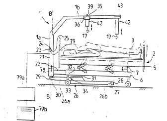
Figures 6 and 7 illustrate a thlrd preferredembodlment of the lnventlon, thls apparatus belng
arranged ln connectlon to a bed wlth an ad~ustable
helght. In lts regular posltlon, the elongate'suEport
frame'1 extends from the head of the bed towards the .
foot of the bed àlong the center~ llne A-A. The''free end
of the support frame, l.e. the second part lb of the
support frame, ls roughly horlzontal and is connected ln
an angular (or curved) fashion to the flrst part la.
The flrst part la of the support frame ls ln the
: ' :
WO90/10427 PCT/F190/000
19 ~ 2 ~ L~ 3
vertlcal dlrectlon fltted ln~lde a tubular mem~er 21
whlch ls fastened to the bed frame 6 by means 'of
supports 22. . -;
The flrst part la of the support frame 1 ls
attached to the tubular mernber 21 by means of an annular
~upport, such as a sll'~lng bearlng 23. The ~lldlng
bearlng 23 rests on top of the top part of the tubular
member 21, elther-freely or as fastened thereto ln a
sultable fa~hlon. At a sultable helght ln the bottom -
part of the flrst part la of the support frame 1, there
ls arranged a bracket, such as a pln 24 or an annular ~ '
flange. This bracket 24 ls suitably fastened to the
flrst part la of the support frame, and agalnst lt the '
elonsate support frame 1 rests on top of the sllding
bearlng 23, and further the tubular member 21 rests, by
lntermedlatlon.of the supports 22, agalnst the bed frame
6.
In the flrst part la of the support frame 1 ~ ~:
and ln the tubular. member 21 there are advantaqeously -.
arranged focuslng means whereby the flrst part la of the
support frame can easlly be ad~usted to be parallel to
the leng~hwl~ dxl~ A-A ~f.the bed, and also easlly and
detachably locked ln thls po~ltlon. The focu~lng means : :
are advantageously reallzed by means of an annular
support 23 and brackets 24. The annular ~upport 23 1~ ' '
sultably provlded wlth at least one recess 25 whereto
the brackets 2.4, such as plns are partially pres~ed when
the flrst part la of the support frame 1 ls parallel to
the lengthwlse axls A-A of the bed.
- - -. Th~ ud~ Lr~n~fer devlce lncludes an
auxlllary support 26,'whlch is.connected to the support
~rame l'.,.in this case to the first:part la of.the `
~;support i'rame,. so tha.t the.auxlllary support.26 turns
`along~wlth the.support ~rame.1' whlle-.lt:.ls t.urnedaon the
horlzontal level wlth respect to the vertical'axls B-B.
The auxiliary support 26 is an-elongate member which ln
the dlrectlon of the second part of the support frame
- - . :. .,, ~
WO90/l0~27 PCT/F190/00064~A `
'~,0~3~3~, 20
extends from the turnlng axls ~-B to a dlstance whlch ls
advantageously at least hal~ of the bed length.
The auxlllary support 26 ls at lts free end
provlded wlth one or several wheels 27, rollers or other
such member which can freely rotate around the vertlcal
fastenlng axls, as well a~ around thelr horlzontal
center axls. In the apparatus of flgure~ 6 and 7, at
the free end of the auxlllary support 26 there ls
arranged a crossbar 28, whlch ls provlded wlth sma11
wheels 27 at glven lntervals from each other.
The auxlllary support 26 1s turnably attached
to the bottom end of the first part la of the support
frame 1, which extend~ through the tubular member 21 to
below lt. Thls type of fastenlng arrangement can be
reallzed by means of a pln 29 and a fork 30. SUch a
flexlble fastenlng method makes lt easler to move the
comblnatlon of bed and patlent tran~fer d~vi~ f~
lnstance from one room to another or from rooms to
elevators, ln case there are tresholds or the 1lke
obstacles ln between these faclllties. Accordlngly,
whlle the haullng app~ratu~ i~ ln lts regular po~ltlon,
l.e. whlle the ~econd part lb of the support frame 1 ls
parallel to the bed axls A-A, the free end of the
auxlliary support 26, provlded with wheels 27, ls free
to move ln the verLlc~l dl~ec~lo~ ultably at least as
much as the sald tre~hold or other bulge, and does not
CaUse problem~ to the movlng of the comblnatlon of bed
and haullng apparatus.
In connectlon to the auxlllary support, there
are arran~ed ~peclal alds for securlng the auxlllary
support rlgldly ln place ln the vertlcal dlrection.
These alds are used:when the support ~rame 1, -
partlcularly lts.s~cond part lb, ls turned at an-angle
wlth respect to the lengthwlse axls A-A of the bed 2.
Thus, by means of these securlng alds, any vertlcal
movement of the free end of the auxlllary support ls
ellmlnated when the apparatus ls belng used and the
WO90/10427 PCT/Fl90/00064
.
21 ' 2~a32
~upport frame 1 ls turned away from the lengthwlse axls
A-A of the bed. Accordlngly, the employed alds can be
varlous mechanical locklng means, whereby the auxtllary
~U~L ~ ls prevented f.om turnlng wlth respect to the
~upport frame 1.
In the embodlment of flqure~ 6 and 7, these
locklng means are formed of an elongate member 31, whlch
ls fitted ln between the auxlllary support 26 and the
frame 6 of the bed 2. The member 31 is lnstalled on top
of the auxillary support 26, at a dlstance from the
vertlcal axls B-B, whlch dlstance ls longer than the ;~
distance of the back plece provlded in the bed frame 6,
such as the transver~al beam 32, from the correspondlng
vertlcal axls. In this case the transversal beam 32 ls
connected to the supportlng structures of the wheels 33
of the bed 2. Thus there is provlded a small slot 34 ln
between the beam 32 and the member 31 when the support
frame 1 and the connected auxlllary support 26 are
parallel to the lengthwise axls A-A of the bed. When ~ ''
the support frame 1 15 turned to an angle ~ wlth respect
to the length~lse axls A-A of the bed, the member 31 l~
shiftedr due to the turnlng step, to below the
transv~rsal bea~ 32 and ls supported agaln~t lt. Thus,
by lntermedlatlon o the member 31, the auxlllary
~upport 26 and the bed frame 6 ln collaboratlon support
the support ~rame 21 whlle the patlent ls belng moved.
Advantageously the top part of the' member 31 ls a
s1ldlng surface, l.e. a surface wlth a low frlctlol,
coefflclent.
- In the embodlment of flgures 6 and 7, the
auxlllary support 26 l~ formed of two parts 26a and 26b.
These parts-are suitably attached on t'op'of eachJother,
so:that the top part 26a ls'fastened`'to the support
frame 1; By means'of this arrangement, the top surface
of the-auxlllary support 26 ls ascen'ded near the bed
frame 6, so that the member 31 can be formed as a
relatlvely low structure. At the same tlme, a
wo 90/1042~ PCl /FI90/00064 ~.
3 ~ :
22
relatlvely large ground clearance ls obtalned for the
transfer device near the turnlng axls
The support frame 1 and the auxlllary support
26 attached thereto are supported agalnst the bed frame
6 by means of the supports 22 of the tubular member 21.
In thls case the supports 22 form a V-shaped supportlng
member, whlch 14 permanently attached to the bed frame
6. Alternatlvely the supports 22 can be fd~n~d : ;,
detachably for lnstance by means of bolts to the bed
frame 6, where there are s~ltably arranged threaded lugs
or other holes for the fastenlng bolts or screws. , -~
In connection to the support frame 21 and the
auxlllary ~upport 26, for in~tance ad~acent to the
tubular member 21, there can be lnstalled a swlvelllng
devlce 78, ~uch as an electrlc motor whlch is, by power
transmlsslon means, connected to the bottom part of the ~ ~'
flrst part la of the support frame 1. Thereby:the ~ :
turnlng can be carried out from a control panel located
for example at the head of the bed 2. ':.
In connectlon to the second part lb of the
support frame 1, there ls arranged a crossbar 35. The
crossbar 35 ls attached to the support frame 1 by means
of ~astenlng members so that lt can be moved along the
second part lb of the support frame and locked at the :
deslred spot. In thls case the fastenlng members
lnclude an aperture 36 or other. lmllar element ln the
crossbar, wherethrough the ~econd part lb of the support ¦
rame ls arxanged to pass, a hole 37 ln the crossbar and ,~
a number of openlngs, such as holes 38, whlch are placed
at certaln lntervals from each other ln connectlon to
the ~econd part lb of tlle support frame l, and a pln 39, i
whereby the crossbar.,35 ls locked,ln.place,,:,by.the~aid , ~ ~
of the apert~re 36 and the holes 37,l~38,-at a sultable ..
. posltlon with respect to the transport of the patlent. ..
The crossbar 35 ls provlded wlth reels 40, ` : .
which are lnstalled in connectlon to the crossbar ln the ,~
vLclnlty of the fastenlng polnt of the support frame 1, ~`. '
WO90/l0427 PCT/FI90/00064
23 2~
parallel to the support rame and also to the bed axls
A-A. At the ends of the arms 35a, 35b of the crossbar
~5, there are provlded foldlng reels 41, wherethrough
the straps 42 are arranged to pass.
In the vlclnlty o~ the free end of the ~econd
part lb of the support frame 1, there ls provlded a
second ~et of reels 43 on both slde~ of the ~upport
frame, 50 that thelr axes are parallel to the lengthwise
axls A-A of the bed. The second set of reels 43 l~
proylded wlth straps 42 in slmllar fashlon as the first
~L 40. Also ln thls case the reels ~0, 43 are loaded
wlth springs ~not lllustrated in the drawings), so that
the ~traps 42 are ln the rest posltlon whlle belng
colled on the reels 90, 43. From these reels, the
straps are pulled down and fastened to the couch 3 by
means of the hooks 17 arranged at the ends of the
straps.
In length the straps 42 are such that they
extend, whlle pulled out, as far as the edges of the
couch 3 when th~ b~L~olll 5 ~f Lhe bed 2 ls llfted to lts
top posltlon. Thls ls carrled out by means of the
haullng devlce 7 of the bottom 5 of the bed ltself.
When the couch 3, complete wlth the patlent, ls fa~tened
to the support frame 1 by means of the straps 42, the
bed bottom S ls lowered by means of operatlng the
haullng devlce 7 ln the oppo-~lte dlrectlon,.so that the
couch 3 wlth lts load remalns suspended from the support ~:
~rall~ 1. Th~s~f~ he second part of the support
rame can be grlpped.and lt can be turned from lt~
regular posltlon, parallel to the lengthwlse axls A-A of
the bed, to a deslred angle ~-to the slde of::.the bed.
~ The turning.. .ls carrled out.safely because
along.wlth the.support frame 1, there ls.also turned the
au::lllary support.~6.. whlch prevents.~the.transfer devlce ~ :
and the bed 2 from.falllng when the angle ~-15 :. -
relatlvely large. : ~:
- Now for lnstance the couch can be brought
- . ,
.... ... . .. . ...... .. .. . .. . . .. . . . . .
:: . . - . . . - : . . .
WO90/10427 PCT/FI90/000~ ~.
2~l3~ 2~ ~ :
beslde the bed and ad~usted to a sultable helght, so
that the patlent can be dlrectly shlfted thereon. The
shi~tlng ls carrled out by detachlng the hook~i from the
couch 3 and by leavlng the couch under the patlent.
When the patlent ls brought back to be~ilde the
bed, the upport frame 1 ls agaln turned to the angle a
wlth respect to the turnlng axl~ B-B, and the qtrapq 42
are pulled down from the reels 90, 43 to besldei the
couch 3, whereto the hooks 17 are attached. Thereafter
the support frame 1 can agaln be turned around the axls
B-B 30 that the second part lb of the support fra~e 1 ls
again parallel to the lengthwise axis.A-A of the bed. ~ .
. The patlent ls shlfted to rest supported by the bed by
1lfting the bed bottom 5 from lts bottom posltlon by ;.::
meanoi of the haullng devlce 7 to lts top poQiltlon, 50 ~;
that the couch and the patlent agaln rest supported by
the bed 2. Now the hooks 17 can be detached and the
straps 92 colled on the reels 40, 43. The bed wlth lts
patlent can now again be lowered to the normal heiqht.
In order to turn the support frame 1 to a : ;
sufflclently large angle ~ wlth respect to the
1engthwise axls A-A of the bed, the wheels 33 of the bed
must be placed relatlvely near to the end where the
hauling device 7 is insta11ed. The auxlllary support 26
ls arranged ln between the said wheels 33, in whlch case
they naturally llmlt the slze of the turnlng angle
Wlth sultab1e arrangements, the size of the turnlng
angle a is obtalned to be at least 45, advantageously ~ .
60 or even larger. These turnlng angles are -
sufflclently w~de ln the regular use of the tran4fer
apparatus oL the present lnventlon. `-
.. ~ Figures 8 and 9 lllustrate another structure :~ .
for.connectlng.the auxlllary support.~6 to the qiupport
frame 1. The bed.2 and lts.$rame.-6 are in-thls~
embodiment lnterconnected ln the-same fashion as.ln ~ :
figures 6 and 7. The support frame 1 is also connected
to the bed frame 6 ln slmllar fashion asi ln the sald
. .
::, .
' ;, .' ' .
W090/l0-S27 PCT/Fl90/000~
~ 2
drawlng~. ~The auxlllary ~upport 26 ls ~olned wlth
bearlngs to the bed frame 6, at a dlstance from the
turnlng axls B-B of the support frame 1. The flrst part
la of the support frame 1 ls attached by means of
tranornlsslon devlce t~ the auxl1lary support 26, by
means of whlch transmlsslon devlce the turnlng of the
support frame 1 lo transmltted to the auxlllary support
26 so that lt also turns to the same dlrectlon.
In the embodiment of flgures 8 and 9, the -
transmisslon ls reallzed by means of the flrst and
second folding wheels 44, 45, and by means of an edless
band 46 or slmllar member ~oining them together. The
flrst foldln~ wheel 44 ls fastened be1Ow the tubular
member 21, at the end of the flrst part of the support
frarne 1. The ~econd foldlng wheel 45 l~ fastened to the
vertlcal axls 97 or the auxlllary support 26. The
vertlcal axls 47 ls attached wlth bearlngs to the bed
frame 6 so that the au~l1lary support 26 l~ free to turn
around the axls along a glven 1lne. The vertlcal axls
47 ls attached ln connectlon to the bed frame 6 so that
lt ls located further from the vertlcal axls B-B than
the wheels 33 fastened to the bed frame. Now the
auxlllary upport 26 ls unob~tructed to turn at lea~t
90 ~lth respect to the lengthwlse axls A-A of the bed.
The transmlsslon ratlo of the foldlng wheels
44 and 95 can be chosen to be sultable. For example,
the transmlsslon ratlo can be 1:1, ln whlch case the
turnlng angle a of the support frame also corresponds to
the turnlng angle ~ of the auxlllary support 26. On the
other hand, the transmlsslon ratlo can be chosen-to be
such that the ratlo a:~ of the turnlng ang1es ls 1:1.5.
In that case the auxlliary support-26 1s turned 90 when
the support frame~1 ls turned 60. . :
~ : .. In connectlon to the~flrst-part la~of the
~u~rt frame 1 and the tubular member 21, there can be
ad~usted mechanlcal guldes, whereby the turnlng angle
ls limlted to be sultable. In the embodlment of flgures
.
: ~ . . , :
;~ . ,:: . . , : - -
wo 9ûJ10427 PCr/FI90/00064,~
2~L1~3~ 2~
8 and 9, these mechanical guides are formed of lugs 48,
whlch are placed symmetrlcally ln connectlon to the
tubular member 21. Whlle turnlng the support frame 1,
the brackets 24 of the support frame are pressed agalnst
the guide lugs 48 when the turning angle ~ h~ L~d~dJ~d
lts maximum.
In the embodiment of figures 8 and 9, the
auxillary support 26 ls provided, ln addltlon to the
rollers 27 located at its free end, wlth another ~et of
rollers 49 arranged in the vicinity of the vertLcal axis
47. In additlon to thls, the auxlllary ~upport 26 can
be attached to the bed fra~e 6 by means of the vertical
axls 47 so that-the La~telllng ls somewhat flexible ln
the vertlcal dlrectlon. In that case the moving of the
bed and tlle attached transfer apparatus over tresho1ds
ls carried out wlthout trouble; near tresholds and other
bulge~ ln the floor, the auxlllary support 26 ls free to
shift somewhat in the vertlcal dlrectlon. On the other
hand, the auxlllary support ~unctlons in connectlon wlth
the suport frame as it should: it prevents the bed from
falllng over when the patlent ls belng llfted, by means
of the apparatus of the inventlon, from the bed and
~hlfted sldeways.
Flgure 10 is a partlal illustratlon of a
fourth embodiment the present lnvention. In thls case ~-
the bed 2 comprlses the bed bottom 5 and the bed frame
6, whlch are lnterconnected wlthout any haullng devlce.
Thus the bed structure conforms to that of flgure 2.
The support frame 1, partlcularly lts flrst ~;
part, are connected to a hydraulic cyllnder 8, wh~ y
the ~upport frame, the couch connected thereto by:strap~
-9, and the patient can be 11fted ln the same fashlon as
was explalned in relatlon to fi~ure 2. In connectlon to
the support frame 1, there ls arranged an auxlliary
support 26, whlch is provided wlth rollers 27 and 99.
The auxlllary support 26 ls attached to the support
frame 1 so that lt ls parallel to the ~econd end lb of
,
\ . ' . ' ., ' . ' ` ' . ,' . ', ' ` ' . ' ' . '.', ' ' :', ' " '.' ' ' .
.:,........ . . ' ~, ' . ~ . . :' ' ' ' . , . : .' , : . ,
' ` " '''.. ' ' ' '"' "' '' ~"' ' :'. ' ' : . " ' . ' ' ' ' ' '
WO90/iO~27 PCT/FI90/00064
2~90'~ ,
27 ' '
the support frame and turns along wlth the frame, wlth '. ;
respect to the vertlcal axls B-B.
The auxlllary support 26 ls fastened, by mean~
of a vertlcal isupport 50 and a sleeve 51 or other
collar-llke member, to the flrst part la of the support
frame 1. The support frame 1 and the sleeve 51 are so
matched, that the flr~t end la of the support frame ~an
move ln the vertlcal dlrectlon wlthln the sleeve 51
dULiny d lif~lng or lowerlng operatlon. on the other
hand, the countersurfaces of the sleeve 51 and the flrst
part la of the ~upport frame are provlded wlth at least
one vertlcal groove and-bracket, whereby the horlzontal
rotatlng motlon of the support frame 1 around the
vertlcal axls B-~ ls transmltted to the vertlcal support
50 and further to the auxillary support 26, so that the
second part of the support frame and the auxlliary
su~or~ 26 ~L~ turned slmultaneously. In thls. case th~
platform 53 ls arranged ln the flrst part of the support
frame and the groove 52 ls arranged on the lnner surface
of the sleeve 51.
The cyllnder 8, together wlth connected
equlpment, can be fastened detachably to the head 54 of
the bed 2 by means of coupllng members. In thls case .'~
the coupllng members comprlse a support 55, whlch l~
lllustrated in detall ln Llgur~s l~ and 13. The support
55 ls formed of a support plate 56, a bottom plate 57 ~ ~ :
and a collar-llke member 58 provided ln connectlon wlth ' .
these two for fastenlng the cyllnder 8, and of at!least
one back'plate 59. In the-support plate 56 and.ln the
back.plates 59 there.. are.arranged correspondLng holes 60 . '''''~
at;.sultable.distances ~rom each other, through whlch
holes the-fastenlng bolts 61 are-inserted.. .~
~ .-The.support'55~is attached to the~head:or the ~ '
bed3so:that~the.head~'59 of the-bed~ls fltted'ln.between
'the support plate 56 and the back plate 59, and by means
of the bolts 61 the support plate 56, the bed head 54
and the back plates 59 are pressed together.
, , . . .. ... ,, . .... ,. .. ,, ~, ., . ,, ~ , .. . . .
WO90/10~27 PCT/FI90/00064 _
2~
~ lgures 14 and 15 l11ustrate a couch 3. The
couch 3 comprlses an underlay 62, whlch ln all essentlal
dlmenslons corresponds to the measures of the mattress
of the bed 2, and support ralls 63, wlllcll are lnstalled
along the long sides of the under1ay 62. The support
ralls 63 are most advantageously ~astened detachably to
the underlay 62. ~hus the long sldes of the underlay ..
are folded on top of the underlay and fastened thereto,
so that there are formed tubular passaqes, whereto the
support ralls are easily lnserted. In order to fasten
the hooks 17 of the straps 92, there are arranged
apertures 64 at the edges of the underlay 62. Thus the
hooks 17 can be easily slld through the apertures 64 and
fastened to the support ralls 63. . `
In thelr mlddle sectlon,-the support rails 63 :
are advantageously provlded wlth artlculatlons 83 and
locklng sleeves 8~, as ls apparent from flgure:16. In
thls drawlng, the two parts of the support rall are
lndlcated wlth symbols 63a and 63b. In between these
parts there ls placed the artlculatlon 83. The lnner
dlameter of the locklng sleeve 84 ls arranged to be such
that the sleeve slldes freely along the support rall 63; .. ~
63a, 63b. In connectlon to the flrst part 63a of the ~ .. .
support ral1 there ls arranged a back plece 85, whereto
the locklng s1eeve 89 can be fastened so that lt extends .` n
over the articulatlon 83 from the flrst part 63a of the j ji -
support rall.to the ~econd part 63b. The locklng sleeve j -~.
84 can be attached to.the back plece 85 by means Or a ¦ ::
crlmp connectlon, l.e. the sleeve 84 ls slmply pushed . ' .: .
around the back plece 85 and.ls.locked ln place by ~ ~:
: frlctlon; on the~other hand,.the end of the.locklng
sleeve 84 can.. be.. provlded wlth lnner threadlngs 84a, and .
.:- respectlvely the-back plece 85 can be.provlded wlth -- ~ :
... .. outer threadlngs.85a-so that the locklng:sleeve 84 can ~.
be fastened to the back plece 85 by means of a threaded
coupling. . ~ .
By employlng ~h~ ~le~v~ ~4, the -~upport ral1s
.:.,. .. : ., ... :. ., .......... .,, : .:: . - , ......... . - : ..
.: : :. : :- , - . - . . . - : - :-::: -~ ~ - :
WO90/10427 PCT/Fl90/000~
~9a32
29
63 are locked throughout thelr whole length to be rlgld,
and are respectlvely released, ln whlch case the support
ralls can be folded. The couch 3 together wlth the
support ralls 63 can thus be permanently lnstalled ln
the bed. The bed and the patlent can be llfted t~ i
slttlng posltlon by releaslng the artlculatlon~ 83 from
the locklny sleeves %~, ln whlch case the support ralls
63; 63a, 63b can be bent at the articulatlon to the same
angle as the bed.
In thls case the couch 3 ls at all edges
provlded wlth detachably connectable support ralls 63,
65 ~flg. 14). The short support rails 65 are fltted ln
the heads of the undeirlay 62 ln a slmllar fashlon as the
lengthwise support ralls 63 along the long edges of the
underlay. The support ralls 63, 65 thu~ forn~ ~
framewor~ around the underlay 62. Owing to thls
framework, the underlay 62 and the connected support
ralls cannot press the sides of the patient whlle the
patlent ls belng transported by the apparatus of the
lnventlon. ~
The underlay 62 of the couch 3 can be ~ ~
manufactured of varlous dlfferent materlals, such as
woven fabrlc or net. Flgure 17 lllu~trates a couch 3,
the underlay 86 whereof ls made of net. The essentlal
polnt ln chooslng the materlal ls to flnd an underlay
whlch can be left ln the bed 2 under the patlent, and
does not necessarlly have to be removed. Thus the
haullng operatlons are naturally carrled out more
easlly, because the underlay ls always ready ln the bed,
under the patlent.
The couch 3 can, wlth sultable modlflcatlons,
be used as a shower base.;~Then thejunderlay 62 `ls made
of some waterproof material. The underlay 62 ls
provided wlth a-hole~66, wh~ch ls mo~L ddvdn~age~usly
located ln the mlddle area of the underlay. To thls
hole 66 there can be connected a hose 67 by means of for
lnstance a regular bayonet catch 66a. From the openlng
WO90/l0~27 PCT/FI90/00064 -
3'~
of the underlay 62, the hose 67 can be further connected
to a sewer or other vessel where the washlng water can
be collected.
Most advantageous1y the hole 66 ls placed in
Lh~ u~ld~r1ay 62 so that lt w111 be located near the
bottom part of the patient'~ body, most advantageously
near the foot of the bed, at the polnt whlch ls 1Owest
when the patlent is restlng on the transfer devlce above '~
the bed, as ls lllustrated ln flgure 15. When
necessary, the couch 3 can, however, be inclined so that
the patlent's head rises hlqher than hls feet. Thl~ ~ '
procedure ensures that while the patient is beinq
Wd~hed, th~ water flows through the opening 66 of the '-~ -
underlay 62 to the hose 67 and further out. ~'-' - '
A~ an alternatlve, the underiay 62 of the ' '
couch 3 can be provided wlth another hole 68, whlch ls ~'' '
larger than the above mentloned hole 66. Thl~
modlflcatlon ls illustrated by a dash line in flgures 14
and 15. The hole 68 is placed ln the underlay 62 more
or le~s at a spot where the patlent's buttocks 1le whlle
the patlent ls restlng on the couch 3. Thls hole 68 ls
u~ed for collectlng the patlent'~ ~ecretlons, l.e. urlne ~'
and excrement, In thls case the transfer devlce ls used ' ; .
so that the patlent ls llfted on the couch 3 up to a
dl~tance from the bed bottom 5, and the bedpan 69 ls set
under the ~econd hole 68, where the patlent can relleve
hlmsel~. Thls ar'rangem~nt means a remarkable ' l :
lmprovement in the care of chronic patients ln i ~
ho~pltals, because now the nurse does not have to llft
the patlent manually from bed and set the bedpan '
lnconvenlently"ln''place". - '' ' '' -
~ In the apparatus of thè''inventlo'n, `=' -`
partlcùlarly:`in''co`n'nectio~n t'o lts suppor't`"fr~ame` 1, there
can be lnstall'ed means for measurlng the 'welqht of the
patient. ' Thus the patlent can bè'welghed wlth'the sarne
apparatus which is used'for lifting and transporting
hlm. ~or example at the turnlng polnt o~ the vertlcal,
:~
., , ,,. ,.
""'' ' "' . "'. ' . '` ' ""' .. ' ' ",'' `, ' . '' ' ' ' . ` .' ',. ' ' "' .: ' ''' . '. , ,. : ~ '' ' :
~ WOgOt10~27 PCT/Fl90/000~
2~'3~3~
31
l.e. flr~t fran~e part la, ln between the turnable
support frame and the statlonary part, for lnstance ln
between the slldlng bearlng 23 and the tubular member 21
ln flgure 6, 'chere can be lnstalled a power sensor 79
for measurlnq the pre~ ure power, by mean~ of whlch
~ensor the total welght of the patlent and the ~upport
frame 1 can be mea~ured. The slgnal recelved from the
power sensor ls proce~ed by means of a sultable
processor 79a, such as a mlcroprocessor, and the
patlent's weight is indlcated for instance in a dlgltal'
dlsplay 79b.
The equlpment for measuring the patient's
welght can be arranged ln connectlon to a hydraulic
cyllnder, for instance ln a connecting pipe 20~ as ls
lllustrated ln flgure 4. The equlpment comprl~es a
pressure sensor 80, which is subjected to the pressure
of the cyllnder space by lntermedlatlon of the
connectlng plpe 20, and a processor 81, whereby the
measurlng slgnal recelved from the pressure sensor ls
translated to welght units, such as kilos, and indlcated
for example ln the dlsplay 82 of the processor 81. The ;
processor 81 can be a ~eparate devlce whlch ls, when
nece~sary, coupled to tlle pre-~ure ~en~or 80 provlded ln
connectlon to the hydraullc cyllnder 8.
In the horlzontal part lb of the support frame
1 there can be arranged varlous auxlllary devlces that
have not been used earller, and also devlces that can be
used in connectlon with the crossbeam fastened to a
hospltal'bed. one of these'new auxlllary devlces, a ''
device for movlng the patient, l.e. a swing devlce 70, '
' ls lntroduced ln flgure 16.
The swing device 7`0 comprises-a crossbar 71, '
~straps 72 or the'1lke-members and a couch 73 whlch ls
a~ranged under the-patlent.' The straps 72 are colled on
reeIs, ln prlnclple ln the same fashlon as wa4
l11ustrated above, for lnstance in'relation to figures 6
and 7. The folding reels 75 are arranged at the free
~ .: . ... ., . : :
WO90/10427 PCTtFl90/00064
32
ends of the crossbar 71, and vla them the straps, whlch
ln the rest posltion are colled on the reels, are pulled
down and fastened to the underlay 73 prlor to uslng the
swing device. The bearlng of the crossbar 71 ls in thls
case reallzed ln a hlnge-llke fashlon at the polnt 77a
above the ~econd part lb of the ~upport frame 1, ln a
dlrectlon at least roughly parallel to the lengthwlse
axis of the bed.
~hen the straps 72 are fastened to the couch ~ -
73 on both sldes of the patlent, and the swing devlce 70
ls ad~usted to a sultable place, ln the mlddle area of
the second part 1~ of the support frame 1, the crossbar
71 can be swinged suspended from the support frame. The
swlnglng motlon ls transmltted by lntermedlatlon of the .
sultably long strap~ 72 to the couch 73, whlch swlngs
the mattress 76 on top of the couch and consequently the
patlent ln the transver~al dlrectlon of the bed. In `~ ~
that case the slde supports of the bed can be llfted up ~-
ln order to prevent the patlent from falllng from the
bed. on the other hand, the angular motlon of the swlng
devlce ln between its extreme po~ltlon~ ls sultably
cho~en, ~o that for the patlent the rlsk of falllng ls ~ ~
nonexlstent. ~ `
The swlng devlce 70 ls advantageously provlded
wlth an actuator such as a hydraullc cyllnder or motor ~ ;
77 for ~wlnglng the cros~bar 71 and further for movlng
the patlent..
By employlng the above descrlbed swlng devlce
70, choronlc patlents can every now and then be moved ln
order to improve thelr clr~uld~l~n. Pa~Llcu1ar1y the
movlng of heavy patlents has earller been trouble~ome
r and required the work of several nurses. Moreover, the
movlng of heavy loads has cau~ed splnal ln~urles for
people worklng ln the nurslng fleld.^- ~ ~
The above mentloned couch 73 can be formed of
the earlier descrlbed couch 3. Accordingly, the swlng
devlce 70 can be reall~ed ln a slmllar fashlon as the
:,
:.. .
. . :~:- - : : :- : - : ,: :
WO90/10427 PCT/~I90/000~
33 '' ~9~3~
crossbar ~5 descrlbed for lnstance ln flgures 6 a~ld 7.
Then the horlzonta1 part lb of the support frame 1~ at a
sultable spot provlded wlth a narrower sectlon, or an
area 90 whlch ls round ln cross-sectlon, which area
should correspond at lea~t to the wldth a of the
crossbar 35, as ls l11ustrated in flgures 19 and 20.
When the crossbar 35 ls deslred to be used as the swlng
devlce, it is shlfted to the area 90, so that the
crossbar 35 Cdll IllOVe Ve~ dlly ln a swlnglng fashlon, '~
supported agalnst the area 90.
Flgures 21 and 22 represent another embodlment
of the lnvention for transferring patlents. In thls
embodlment, the support frame 1 ls composed of the ~'
essentially vertlcal frame parts la and 1c, whlch are -
arranged at both head~ of the bed 2 and are astened to
the haullng equipment, i.e. to the hydraulic cylinders 8 '-
and 8'. Furthermore, the support frame 1 comprlses an
essentla11y horlzontal frame part lb dlvlded l'nto two
sectlons lbl and lb2, whlch are permanently connected to
the frame parts la and lc provlded at the heads of the
bed.
The sectlons lbl and lb2 are ~olned by means
of the sleeve 19 whlch ls movable along the lengthwlse
dlrectlon o the frame part lb. The sleeve 19 can be
locked ln the ~unctlon for lnstance by means o~ a pln ~'
19a, as ls 111ustra~ed ln l~ure 2~
The flrst horlzontal ~ectlon lbl of the
support frame 1 and the vextlcal part la correspond in
structure to the frame parts lb and la o flgures 6 an~
7, for example. Thus the horizontal sectlon lbl ls
turnable, after' releaslng the sleeve 19, sldeway~ to an
angle ~ with respect to the lengthwlse axis A-A of the
bed. Thls frame part lbl can be provlded wlth all of
the auxillary devlces that have been descrlbed above.
As an alternatlve for the modlflcatlon of the
embodiment of flgures 21 and 22, the vertlcal frame
parts la and 1c of the support frame 1 can be fastened
i
WO90/10427 PCT/FI90/000~
7 ~ 5~2 34
to the bed frame 6 ln a statlonary fashlon, as ls
lllustrated ;.n figure 23, provided that the bed bottom 5
is vertlcally ad~ustable ln relatlon to the bed frame 6
~cf. figure l). The 11ftlng and lowering of the patlent
ls carrled o~t by llf~ltly dll~ 1Owerlng the bed bottom 5,
so that the haullng devlce 7 pertalnlng to the bed ls ~ -
made use of. The horl~ontal sectlon l.bl and the
vertlcal part la, together with connected equlpment, can
be turned, supported by the tubular member 21 ~cf.
flgure 6), sldeways to an angle ~ wlth respect to the
lengthwlse axls of the bed.
In this embodiment the couch 3 is similar as
ln the above descrlbed transfer devlces accordlnq to the `~;
lnventlon. The couch 3 ls advantageously made of some
flexlble materlal, cuch as woven fabrlc or net. At the
sides of the couch 3, on both sldes of the bed 2, there
can be fltted support ralls 18 tcf. flgure 3), whereto
the ends of the straps 4 can be fastened while the
patlent ls belng moved. :~
In the above speclflcatlon the inventlon has
been descrlbed malnly with reference to a few preferred
~ulb~di~ rl~s~ but lt ls naturally clear that the
lnventlon can be modlfled ln many ways wlthin tne
inventional ldea deflned ln the appended patent clalms.
~ '"'