Note: Descriptions are shown in the official language in which they were submitted.
y . Angular Paving Stone for Paving Areas
The invention relates to an angular paving stone of
soiidiiying material for paving areas, comprising two
outer sides, two inner sides and two face sides.
They may be characterized
known
.
Angular paving stones axe
n angle
t
a
the effect that two stone legs extending a
to
ach other are integrally united with
with respect to e
Angular
et
..
each other at the location where the legs me
rovide the advantage that, when laid in
, paving stones p
f like anguJ-~' ~'~~g
interlocking fashion, i.e. when a plurality, o
ide each other, a mutually interlocking
b
es
stones are laid
nes results. '~his is ad-
t
o
arrangement ~of the angular paving s
for the carrying capacity of the paved area
vantageous
of angular paving stones arranged in
and when a group
a clamping ,
d b
y
composite or interlocking manner is graspe
engaging laterally on the outside, and is laid .
i
pper
gr
in doing so, the risk is
o
ups
in this manner as a gr
ll down
f
~o:~s ~vi
r a
minimized that individual stones inadvertently
,: rasped group before the group is laid as a
-, the
f
g
rom
certain degree disadvantageous
whole. However, -it is to a
t to angela~r paving stones that the joining
;+.r o~oec
w_ __. r~_
region of the two stone legs is subject to comparatively
high loads when lateral forces act on the free ends of the
stone legs. Therefore, there is a tendency towards the risk
t'.~.at cracks starting from t~~e inner corner, ~.ri~~era the t~ao
inner sides meet, will be caused in case of excessive'loads.
n addition thereto, the ',cnow-n angular paving stores navy ,
the disadvantage that they allow water, to seep away only
to an insignificant extent - through the gaps between
adjacent stones.
rt is the object of the invention to make available an
stone which renders possible a considerably
angular paving
eased discharge of water into the paved area than it would
incr
ossible through the gaps betweenangular Paving stones laid ad-
be p
'acent each other, and which presents a broken-up, interesting, but
7
nevertheless uniform and calm appearance when laic in '
interlocking fashion.
To meet this object, the angular paving stone .according ~to
the invention is characterized in that quarter recesses
w are provided at the five outer corners of the angular
awing stone where the two outer sides meet and where outer
p
sides meet face sides and inner sides meet face sides;
that half recesses axe provided at the center of the outer
stone; and that a three-quarter
sides of the angular paving
recess is provided at the inner corner of the angular
awing stone where the two inner sides meet; the quarter
p
recesses, the half recesses and the three-quarter recess
being provided such that, when like angular Paving stones
are laid adjacent thereto, full recesses are formed at
w all locations by mutual supplementation for discharging
l~~:J .~
water into the layer located underneath.
., . ,. .
~dith the angular paving stone according to the'invention,
the at first seemingly bold path was taken to weaken the
stone by material removal. due to the comparatively large
three-qLarWer reCecc a ~ tt'?e i nnar CCr:':er r i ~~ -'
joining region of the two stone legs. It surprisingly has
r-c ' 'i-.= ';aL="' 1 =~°-:O V~_ ?~ n0 ~=7~~W'~
tI~_:S,..Q OL:.e. u.:!Gt.. C.._J -
effects on the strength of the angular paving stone. This
is attributed to the fact that the critical inner corner ,
point proper has been abandoned so that this concrete
starting point for stone cracks is eliminated.
t. Configurations with equally long stone legs and/or with
stone legs extending at right angles to each other are
preferred for the angular paving stone according to the
.;:;i
invention. Preferred, practical materials for the angular
rc.ving svO:a2 aic Ce.i.E.' it- Or plasClCs-seCti: y.Vll~.lC4c~
or brick materials. These materials have solidizied
when the angular paving stone is ready for being laid. The
angular paving stone preferably can be laid in a plurality
of laying patterns, as will be shown by the embodiments
hereinafter, and results, with an arbitrary laying pattern
selected, in the desired supplementation oy the quarter
recesses, half recesses and three-a_uarter recesses so as to
form full recesses. The angular paving stone preferably
does not have holes or openings in the interior of the stone;
the improved water discharge into the layer underneath is ,,
to 'take place through the full recesses. The quarter
recesses, half. recesses and three-quarter recesses are
located at the edge of the angular paving stone and can
be made there with less problems than openings in the
interior of the stone.
:'~lG~. ~ . . , .
The angular paving stone preferably serves for being laid on,
outdoor areas. Preferred fields of use to~be
or paving
mentioned are roads, yards, footpaths, industrial areas,
squares, garage drives and the like.
_ _ 2~~~~0~0
In the paved area, the full recesses can be filled '.with ~
a suitable filling material - for instance sand. fine
gravel, fine chips, ashes, or the like - preferably
,. .,~. ; ~r to~e top sia~s o~
to a level o. the ang"1 a_ ~ m_.. . s ..
sl_ghby b~lOw.
It is preferred when the outer side of the angular paving
i stone is twice as long as the inner sides thereof and as
the face sides thereof. This provides an angular paving
stone having balanced proportions and a particulary great
variety of possible laying patterns.
The angular paving stone preferably is designed as an
interlocking paving stone having protrusions and retractions
on all sides for. interlocking engagement with like
...7.:i a ynGs'j.:a~y St:,ne5 plaCeG ther2agal.nSt. '1'h2 protruSi.OnS
~ a:ld r2traCtlonS beCOme mOSt evident when viewed in comparison
with the basic configuration of the angular paving stone,
in which the five outer corner points and the inner corner
point - which are cut away by the quarter recesses, half
recesses and three-quarter recesses - are connected to each
other by straight connecting lines. For instance, when two~ ~
identical angular paving stones are placed adjacent an outer
side of the angular paving stone having protrusions and re-
fractions, the latter paving'stone interlocks the two ~
neighboring stones with each other i:~ positive manner. ~
i
This provides a particularly high loading capacity of the
I
f paved area and a particularly good coherence of an actually
loose group of angular paving stones when laid in common
by means of a clamping gripper. As regards the concrete
~ geometric design of the paths .of the protrusions and
retractions, there is a large variety of possibilities, with
~ ,~ some preferred ones thereof being shown hereinafter in ~ ~
the embodiments. Serrated or corrugated paths or pa~terns.are
i
preferred in. general. Regular paths as a rule yield
the optically most pleasing angular paving stone configurations.
An especially preferred angular paving stone configuration
i c chdr2.Cteri Zed in that - GThen the quart°r reCeSSeS, the
half recesses and the three~quar.ter recesses are conceived of
as being closed - each outer side consis~s of Two iaenzicai
outer side halves, each inner side corresponds to an outer
side half and is parallel thereto, and each ace side
corresponds to an 'inner side and - generally speaking -
is disposed at right angles to the adjacent inner side and
the adjacent outer side. This design can be realized both
with rectilinear outer sides, inner sides and face sides
Lr. ~ and ret=?ctions.
-. aWd witsi Stones SidcS having vro....i..lslvn S ,
p particularly preferred embodiment of the invention is
characterized in that the quarter recesses, the half
recesses and 'the three-quarter recess each have provided
thereon a marginal strip piece or section that is Set O== w1'Cn
respect to the top side of the angular paving stone, so ' that
the full recesses are surrounded by a set ofd marginal
strip. The marginal strip pieces may have downward slopes in
the direction towards the recesses,and in particular they may
extend downwardly to the recesses in the form of inclined .
areas or in funnel-like manner. The setoff of the marginal
strip nieces with respect to the angular paving stone top
side can be provided by the downward slope or in particular also
by a step-like lower placement thereof or a combination of
both thereof . Marginal strips with a downward slope direct water froze
above in funnel-like manner into the full recesses. In
articular in case of marginal strips surrounding the full
p
recesses and having a downward slope towards the recesses,
for instance earthy contaminations of the top sides oz the
"filling material plugs" can be swept away comoarativelv
easily, also with motor sweepers, since the sweeping brushes
' meet abutment areas at the edges of the full recesses.
The result is an area paving which can be regenerated and
as a whole allows the passage of water and in ~rhich
.. ,~,.~
,..r. ._
;: s : , ~ ..
r
:.~. .f. ..
,r ,a~.. .~ :~,
...;.,~.. . ,< r, ..,rte ., , ~, ?'. ,, ~:..~., Y,. ,, .,t.- r.v-'al". !x f ;.
,.51~~.. t" ~~P:
. . ~ .., ~ . ' f ~. .. , ;," . .
- o -
contaminations in the upper region of the "filling material
C 2, n ~. 2
1 ;-:a'vS ... C OCr;::,~ °..°C~,
..lucs", '~hic:, pcssib_:r .=
removed without any problem.
It is pointed out. that the measures described in the pre-
ceding paragraph may be realized according to the invention
also with stones of cement-setting material for paving
areas, which, otherwise do not have the features indicated
Concretely~speaking, such stones may be stones
in claim 1.
Which d0 nOt ~=~Ve an a:':g'llar Con fig'.,'.rati.0:1 a:''.C~Gr Which
have partial reCesSeS Which supplemenT- eaCii o~.her SO as
to form full recesses but which are not necessarily as well
quarter recesses at the outer corners, half recesses at
center of the outer sides and a three-auarter recess atthe.
the
inner corner.
The top side of the angular paving stone preferably is sub-
divided by two dummy gaps into three optically alike top
side portions. The result hereof is that the ~.ngular paving
stone orientation in the paved area is practically not
visible any more. An analogous result is achieved when -
as is preferred as well - three mutually alike raised
portions are provided on the top side of the angular paving
stone . .
,,
According to a.particularly preferred embodiment, the top
side of the angular paving stone is provided with durcimy
in the half-recesses and the three-quarter
gaps terminating
recess or.terminating in the corresponding marginal strip
pieces. The result thereof is a particularly efficient'
t..~;,~;.:, water discharge to the "dummy gap connected" full recesses.
It is expressly pointed out that the measure of the "dummy
~ , ~~ artial recesses or the marginal strip
gap connection of p ,
'eces thereof in case of stones of cement-setting material
pi
for paving areas is also technically sensible. per se, i.e.
2~3~~~~~rO
without simultaneous realization of the features indicated
?,nG~ thL.2S C°..~_ ho real iZ°~ ~°. S'
_n - -c 1 a =.~.i 1 .
Preferaby, the full recesses between the angular Paving
stones are of square or round configuration as seen in a top
plan view.
The considerably increased water discharge, rendered possible
according to the invention, into the paved area through the
o presenting a clearly increased overall
roll r..cesses ~ ~~
lYatGr CI~.Jcilar~e cr~Sj~Ject.L.~nGl area t~-~.n t..... gG~S
L.~~'..ai.'N~G.~~.al
. ..
the laid stones, has the effect that paved areas no longer
ed to be connected to a drain system. Due to this fact
ne
'. b savings i:n drainage and sewage systems, considerable
and y
costs are saved. Rather, water from above, in particular
rain water, is passed into the underground, and this
ontributes in keeping the groundwater level in desired , .
c
manner as high as possible. Plants growing nearby receive
sufficient water. Besides, even in case of heavy rainfall,
since the
awed area,
there is no water accumulated on the p
water is discharged into the undergound at many distrib-
uted locations. When dummy gaps and/or recessed portions
are present between raised pore=ons, Par=icularly r=Pid de
r' watering and drying of the paved area is achieved.
ointed out that the full recesses may also
Finally, it is p
be closed partially by means of plugs, e.g. of plastics
material, provided'with water discharge channels.
;:,'~°;~~i 'a
~~~~~~7~
- _
the invention and further developments of the invention
will now be elucidated in more detail on the basis of ' ,
preferred embodiments shown in the drawings, in which
Fig, 1 shows a first embodiment of an angular paving stone
having partial racessas%
gig. 2 shows a second embodiment of an angular paving stone
having partial recesses;
Fig. 3 shows a third embodiment of an angular paving SLOr_e
~_: having partial recesses and raised portions;
Fig. ~ shows a fourth embodiment of an angular paving stone
having partial recesses and marginal strip pieces;
Fig. 5 shows a fragment of an area paved with angular
paving stones according to Fig. 4.
Fif. 6 shows a vertical sectional view along the line
VI-VI in Fig. 5;
Fig. 7 shows the fragment of the area according to ~'ig- 5, .
however with the full recesses being filled; ,
~:.:
Fig, g shows a schematic view of several possible laying 1 y,
patterns of angular paving stones.
, A11 drawing figux'es1 with the exception of Fig. 6 show the
awed area, respectively, in top plan
paving stones or the p
i
views.
y ,~
' ~ . .
.,
" ..
. . ... ,. .
v ' . . ._.. .., ..~ ~. ~ __.~...,_-~. . -..~_.==.--
_ . _.. __ . ..__._~ """'"w-a...~.~:
.z. .
,.
. ~.~,.
...,.
:, ,
.,..;
r .. .~W, ..A .;.a., t v.~'~ ._r.
." 7 izt ~ . .-r. . ,-,,'X~~lr -n,.~.~:<9 . .~,a.:'E:.
r... . ~ ~., ~ ..,v ..a...,, :....:.'..' .,t, , .~:v ,.'~,. ~ .'. , , ..:~ .
,. . .:.. ~..~~.: ~ : ..:.'.G~.,i~ .,.: . '.'.,'.:..,.:..
,s aa,.., x
J....
.. ,: .,,. .. .'... ~y, ' .,: '.. , ~.
,. )',., ", 4y 'w't. ; a Y,
~ v , , . . . .. . ...
''.. ~ , ' ,.. - ' .~' : , :,~ .. , : . 1 '.y. , ,. , . , '
- 9 -
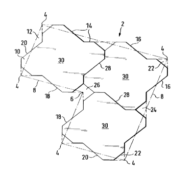
2 shown in Fig. 1 has five outer
The angular paving stone
When making
6
.
orner points 4 and one inner corner point
c
8 between these corner points 4,
straight connection lines
ar
'
...
-,e 'les at ~e asic CO::-_y:-at=...:: ~_ '.~ aWj~:.
~..
arr
_
This basic configuration can be characterized
. paving stone 2.
G ci:~2uC~.i.~
an
JO si.0i12 :.~C~ Oy. 2 =::ai ! city
'
'
~
-
.
.
.
lr.
~._. ~.
united with each other
at right angles to each other are
n angle of
t
a
a joining region extending obliquely a
l
ong
a
the inner corner point 6 to the
45 and leading from
opposing outer corner point 4.
ides follow a path which - when y .
The angular paving stone s
e disregarded
a
r
described hereinbelow
the partial recesses
rth with respect
f
.
o
the time being - extends back and
for
8 so as to form protrusions 10 and
to the connection lines
id
th o= the stone sides with sa
retractions 12. The pa
defined by rectilinear
i
s
rotrusi.ons'10 and retractions 12
ct
p
tending in angular manner.with respe
side sections 14 ex
f the side sections 14
to the connection lines 8, with part o
d
r angle with the connection lines.8 an
including a large
including a smaller angle
the remainder of the side sections
formed
lines 8. Tn this manner, there are
with the connection
xtend at r~gr_a
r sides16 which generally speaking e
t
i
e
ng
two ou
18 which generally speak
. . ,
angles to each other, two inner sides
ides 20
i
t right angles to each other, and two face s
extend a
the
t right angles both to
d
,
a
hich generally speaking exten
w
ide 16 and the adjacent inner side 18.
..:; adjacent outer s
t;i
oints 4, where the t~ao outer sides
er
u
p
ter corn
At the five o
ide 20 meet
where an outer side 16 and a face s
16 meet or
side 18 meet, there is
or where a face side 20 and an inner
in other
e triangular quarter recess 22 each. Or
d
. on
' provide
is obliquely cut away
fi ords: the outer corner point proper
' ' r sides
w
er point 6, where the two inne
' there. At the inner corn
rovided a three-quarter recess
is
' p
18 meet, there
', '
a ,
'
....,....T_......,: ..r,;a.':a.;.
S. ...
p .< y;f:
t 1. ill:, a .r>a
. '~~ . a.
.., ,'f r-' c
1 . .r . - .r
.., y ::.i::~ a .. .,~.. _. ~.:
,Z., , s. , ... Y, ru. "' . .F .r . ..s .r
,
'.:~. n
n-T.'.., n"./~:.~ n..la.v .n
7 5.1
,_,..~~..." , ,~, , .
: ~
~
"~'
~
~
'
''
,
,,.
:
. .. , .
y
:'
.
..
. . . ., :~ ,_ .. ,::.' ~!S:. . . .::..; n. .~;~ ; ai.
'
. ; .' .,... ..
. ,..... .:. ,. .. ~ ...",:- n. ' .._... . . : . '. '
, -
'. y ',;
' ..
.,. ' . , '..:. . . ... . '. . .'., . ' ...,.~ .. .':..,' ' '., .
.. .;,. ..
.,V'.. :' . '.. ,... ". .' .. .:~. . . ,. '.: ~~..~ .... . ,.' -'...
', . ..; '
: ..; ;:.'. .:...: :~' ~, .~ .-.': '.:,. ~ :'i.;.,. f.,. .'.~
'...,~ '.. _. : ,;..;.
'
~ ly . . ~,..~.'... ..' ..~ :..'.'v... ". ~~, n ...., :. ' .;
.:~: '....'
2a~~90'~0
- 10 -
which has the configuration of a square with one triangle
S°C to= .~.?isSi!'?C, Cr in pt1?e,.. -~n'O-'~S: a :.".at°=ial
.~.C~t'_.rJ:: 1S ...
cut away there from the paving stone 2, which is confined by
three sides o= a square. In the middle portion oz each outer .
fv'' side 16 there is provided a half recess 24 having the shape
oz a triangle. Or in other words: a material portion is cut
' away there from the paving stone 2 which is defined by two
sides of a triangle. The half recesses 24 each 'nave twice
the area as the quarter recesses 22, and the three-quarter
reCeSS ~6 haS thrlC° the area pf a qL.?rtcr raCggc 77,
Moreover, it is possible to see two dummy gaps 28 in Fig. 1
which each extend from the three-quarter recess 26 to the.
opposite half recess 24. Due to the dummy gaps 28, the
top side of the angular paving stone is optically sub-
divided into three equal top side portions. As seen in"a
vertical sectional view, the dummy gaps for instance are
substantially of triangular or inversely trapezoidal con-
figuration. They have a depth of several millimeters.
At the transition from the topside of the paving stone to
the vertical paving stoneysides, a small bezel is preferably
.I
provided everywhere,, which is not shown in the drawing
for reasons of clarity.
When the partial recesses 22, 24, 26 described are imagined
as being closed or not present, the outer sides 16.each
consist of two identical halves placed against each other,
each inner side 18 extends parallel.and corresponds to
the opposite outer side half, and each face side 20
corresponds to an adjacent inner side 18~or to an adjacent
outer side half, however rotated through 90° The dummy
arallel to an associated face side 20.
,.gaps 28 each extend p
2~~~~'~0
_ 1 1 _
When several ones or the angular paving stones 2 shown
in Fig. 1 are laid adjacent each other
in one of several possible laying patterns, the quarter
rQCC~scS 22, half reCeSs2s 2= anC tnre2-quarter r2CeSS2S 2~ y.
at all locations on the paved area supplement or complement
each other so as to form square full recesses o:.'equal size
at all locations. Thus, a picture of the paved area is formed
which is determined by a regular alternation of top side
portions 30 and full recesses and thus has an appearance
which presents on the one hand a broken-up and interesting,
bllt - ~~VOn t~':e Ot~'?°r hand a, ll_nlfOrT_:; a??d Calm effect.
The angular paving stone 2 according to Fig. 2 differs from
the angular paving stone 2 according to Fig. 1 merely in the
configuration of the partial recesses 22, 24, 26. The
quarter recesses 22 have the shape of a quarter circle, they
half recesses 24 have the shape of a half circle, and the
three-quarter recess 26 has the shape of a three-quarter
circle.
The angular paving stone 2 according to Fig. 3 differs
from the angular paving stone 2 according to Fig. 2 merely
in 'that no dummy gaps 28 are provided, whereas three equal
circular raised portions 32 are provided in evenly
distributed manner on the top side of the paving stone.
between the rai,sed~portions 32 there are provided channel-
and face-like Portions 34 which axe located at a lower level
and through which water can flow to the recesses.
The angular paving stone 2 according to Fig. 4 differs
from the angular paving stone 2 according to Fig. 1 by
shorter, rectilinear dummy gaps 28 and marginal strip ,.
~ ~ pieces 36 at.the partial recesses 22, 24, 26. The marginal
strip pieces 36 either have a horizontal topside and are
plac°d at a lower level in step_like r.,anner with respect to
the remainder of the paving stone top side. Or the marginal
20~~070
- 12 -
strip pieces 36 have a downward slope oz even area in
the direction towards the particular partial recess 22, 24,
26. Or a combination of both of these measures is pro-
' L -y .. ..
beg 3~ e=C.. ..'.10_~..~y :-~=a ~ -,..1
Vider7 _Tl,e marginal S''rip .fl ,.
recess edges with a uniform width, with the ends thereof
being each terni::ated i.~. oblique .:ar.~ser. I~ vie~,a o= rho
.
marginal strip pieces 36, only the rectilinear central
portion of the dummy gaps 28 has been left: The dummy gaps
28 terminate in the marginal strip pieces 36.
Fig. 5 illustrates the appearance of an area paved with ,
' ~.y' the angular paving'stones 2 according to Fig. 4. It is
possible to recognize the regular alternation of square
top side portions 30 and square full recesses 38 which
are each surrounded in square manner by a set off marginal
strip 40. The surrounding marginal s'.-.rips 40are composed
of quarter marginal strip pieces, half marginal strip
pieces and three-quarter marginal strip pieces.
One can see in the vertical sectional view of Fig. 6 that
:;~ the dummy gaps 28, as seen in section, substantially have
the configuration of a somewhat rounded triangle standing
~~'~ and that the angular Paving stone top side has
on its tip,
a small bezel 44 which extends all around the latter and
'', has the same depth as the dummy gap 28. The marginal strip
piece 36 shown in the drawing extends in roof-like manner
obliquely downwardly to the full recess 38 and joins the
lower end of the portion of the bezel 44 located there.
stones 2 are laid on a sub-layer 46
The angular paving,
of sand or the like.
.L Fig. 7. illustrates the appearance of the paved area after
the full recesses 38 have been filled with a suitable, .
,, : . , .
,, ; filling material 42. As shown, the filling material 42.
,.,
zo~oo~o
- 13 -
may cover the top sides of the marginal strips 40 with a thin
layer thickness, but this is not necessarily so. In the first-
mentioned case, the paved area presents therappearance of .
a r2gu.lar alLernatl.o : yctW2e:, rals2Q pOrt1.0i1S 3~ Os larger
square area and portions with filling material 42 of
s~Tictll 2r sqiidre c.r2G.
All embodiments shown in the drawings had stones sides
with a zig-zag like path of protrusions/retractions.
Instead of this, it is also possible to choose other
oaths of the stone sides, for ir-StanCe a SL~''JSt~'-'-ti,'~11y
corrugated path. The same applies in corresponding manner
to the dummy gaps 28.
Fig. 8 shows several possibilities of laying angular paving .
stones 2 according to the invention in interlocking fashion
or in the laying pattern, respectively, with each angular
paving stone 2 being shown merely by an angled line.
. Fig. 8 at the top shows a variant in which two angular
paving stones 2 each ar.e placed against each other in opposite
orientation so that they form a rectangular paving
piece. Fig. 8 in the middle shows a variant in which the
individual angular paving stones are arranged in rows ~-_4
;, in the same orientations within each row 44 the inner corner ,
~".:
.6 of an angular paving stone is placed against that outer
corner 4 of an adjacent angular paving stone 2 where the
two outer sides 16 meet. The variant shown in Fi.g. 8 at the
bottom differs therefrom merely in that the rows 44 are
alternatingly arranged in opposite orientations. The laying
pattern shown in Fig. 5 corresponds to the variant shown
in Fig. B i.n the middle, as can be seen from the marginal
atterns -
strip pieces 36. In all of the possible laying p
. I .,...
which are more than those shown in Fig. 8 - there is created
a mutual supplementation of the quarter recesses 22, half
i
recesses 24 and three-quarter recesses 26 so as to form
full recesses 38.
The paving stones 2 including the marginal strip pieces or
sections 36 are integrally formed from for example concrete.
r'~',I ,
,.;:,~ ,., r , ..,.~ '. ,.~x "'
~ :. . . : f.~, o.., .
..z~~.-.d
T,~ . ,.,
.. '.,.,, : ;?' , . .'.. . :~' , . :: . ? :_ '.
,. ., - . .;.n , ~.,;,.. ,. , .. . . , V ,.. '._ ~~.. i.'.. '.' , ... . .
" '.. .. '. .,.. ...,~: . . ~ m , . .,. , " .. .,.,.,. ,
., ~ "., . , Y .. '.. ~:. . y ~~ ~ .. . .S'. . .. .',:. ; '..