Note: Descriptions are shown in the official language in which they were submitted.
Background and Summary ~ A 21 4 q 1 07
Male external catheters are commonly formed by dlpping
a mandrel into baths of an elasto~er such as latex and curing the
latex between succes~ive dipping operations to build up a catheter
wall of deslred thickness. Thereafter, the catheter
is removed, usually by rolling it off of the mandrel
so that it assumes a rolled condition in whlch it is
subsequently marketed.
Whlle the latex-dipping steps are conventional and
are similar to those carried out in the manufacture of
latex gloves, the further requirement that such a catheter
be lnternally lined witA a band of pressure-sensitlve
adhesive complicates manufacturing operatlons. ~urther
complications arise from the fact that the provlslon of such
an adhesive coating also re~uires the outer surface of the
catheter to be treated with a suitable release agent so that
when the catheter is rolled into lts marXeted form it may
later ~e unrolled by the user.
The extent of such complexities is illustrated by
publlshed International Application WO 86/00816 based on
PCT application PCT/DK85/00068. There the steps of applying
the inner adneslve layer and the outer release layer are
performed only on a pre-formed catheter. In one verslon
an adhesi~e strip 5 is first wrapped about a mandrel 7
having ducts for the discharge of air under pressure (~igure
5). A catheter ls fltted upon the mandrel while alr is
simultaneo~ly discharged rom tile ducts to expand the catheter
and prevent lt~ inner surfaces from prematurely contacting the
adhesive strip, When the catheter is in place, the flow of air
is discontinued and the catheter is allowed to contract into
2 -
~A 2 1 49 1 07
contact with the adhesi~e, Thereafter, a release layer
strip 6 is wrapped about the outer surface of the catheter,
and the catheter is f~nally rolled off of the mandrel. It
is believed apparent that such manufacturing operations are
labor-intensive and involve complex manipulation that are
not easily automated.
U.S. patent 4,475,910 also dlscloses a manufacturing
method in which an inner adhesive layer and an outer release
layer are applied to a pre-formed catheter. In that method,
the release layer ls first applied to the outer surface of
a catheter supported by a mandrel and, after the release
layer is cured, an adhesive layer is also applied to the
outer side of the ca~heter over the release layer. The
patent does not specify ~ust how the pressure-sensitive
adhesive layer ls applied but, since no mention is made
of drylng or curing the adhesive, that layer is presumably
transferred to-the cat~eter in lts flnal tacky state from
an adhesive-bearing transfer strip or the like. Wh~le
Qimpler than ~he procedure described in the aforementioned
BritiQh applicat~on, the methodology dlsclo ed in thls
patent nevertheless ~nvolves steps that are dlf~cult to
automate,
Accordingly, a main aspect of this invention lies in
provlding a method which may be readily automated and
performed on a continuous basis (in contrast to batch
basis). In its slmplest form, a mandrel is exposed to
a series of dipping and drying ~or curing) steps for
purposes of forming the catheter and the adheslve layer (and, where
required, a release layer) on it= opposite surfaces.
. .,_
`,~
~ ~A21491C7
A d~itlnctive feature of the method of this ~n~entio~
lies in applying a layer of adhesi~e, preferably by means
of a dipping operation, directly to the non-stick surface
of a mandrel during tAe first step of the manufacturing
procedure, Thereafter, by a ser~es of dipplng and curing
steps, a catheter i8 formed on the same mandrel over the layer of
previously-applied adhesive. Unless the elastomer becomes its own
release coating - as in the case of silicone rubber, for example -
following curing of the elastomer, the mandrel i6 again dlpped, this
time in a bath Of release agent, to coat the outer surface
of the catheter and prevent the adhesive from adhering to
the catheter's outer surface when the f~nished catheter
is rolled off of the mandrel,
Therefore~ ln brief, the method ~nvol~es the steps of
applying a medical-grade, pressure-senslt~ve adhesive to
the release surface portion of a r~gld mandrel to form
a wea~ly-adherlng adhesive coatlng thereon, then dipplng
the mandrel into an elastomer bath to form a first elastomer layer
over the mandrel and the adhesive coating and curing the elastomer
layer, repeating the elastomer dipping and curing steps until a
desired wall thickness for the catheter has been formed, then, where
required, dipping the mandrel in a silicone bath to form a release
coating upon the catheter, and finally curing the relea6e coating
and rolling the finished catheter off of the mandrel.
In an especially preferred embodiment of the invention, the
mandrel is vertically oriented and has a generally cylindrical body
portion and a reduced lower end portion. ~he adhesive coating is
washed away from the surfaces of the reduced lower end portion of
the mandrel and a part of the cylindrical body portion adjacent
thereto, to leave only a band of adhesive about the cylindrical body
part.
, . .
-- 4 --
~A
Other features, advantageR, and ob~ects of the invention will
become apparent from the ~pecification and drawingo.
Drawin~s ~ ~ 2 1 4 9 1 0 7
Figure 1 is a flow chart setting forth basic steps of the
method of this invention for making adhesive-lined catheters, and
including additional steps specific to the use of an elastomer such
as latex, which requires the provision of a release coating.
~ igures 2-7, inclusive, are sChematic views dep~cting
certain of the steps of tAis method.
Pigure 8 is an enlarged side elevational vlew
illustrating d finished catheter made in accordance wlth
the method of this invention.
Detailed Description of
Preferred Embodiments
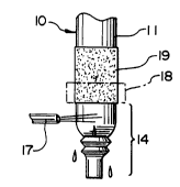
All of the method steps described herein are performed
in relation to a mandrel or form 10 of the type depicted
ir~ Figure 2, Such a mandrel typically has a cylindrlcal
body portion 11 and a reduced end portlon 12, Sultable
supporting means 13 supports the mandrel and advances ~t
into and through the successive treatrnent ~tat~ons although,
theoretically, such supporting and advancing functions
might also be performed manually, While each catheter
may be totally manufactured on a single mandrel, as
described herein, it is also to be understood that there
may ~e special circumstances making lt more desirable to
transfer a catheter from one mandrel to another at some
point in the sequence of fabrication steps.
It ~hould also be noted that, in the following description,
the latex elastomer does not form lts own release coating and the
described method therefore includes the provision of such a coating
from an external source. However, as will be apparent to those
skilled ln this art, if an elastomer such as sillcone rubber (whlch
-5~ - 20491 07
forms it own release coating) is employed, no additional release
coating is needed and those steps in the process described below
which relate to the application of the release coating are
redundant.
The first step involves the applying of adhesive 16
directly to the surfaces of the mandrel. Such applicati~n
is preferably, but not necessarily, performed by means of
a dipping operation in which the mandrel i8 s~pported in
vertical condition with its reduced end 12 facing downwardly
and is then lowered into a bath of liquid adhesive.
The surfaces of the mandrel should be capable of being
wetted by the adhesive but should nevertheless resist
sticking of the adhesive during the final stages of
catheter manufacture. More specifically, the npn-stick
surface of the mandrel and the composition of the adhesive
. .
2049107
should be formulated so that the adhesive will adhere
weakly to the mandrel but may later be stripped away
without leaving an adhesive residue on the mandrel.
With the preferred adhesives described hereinafter, it
has been found effective to utilize an aluminum mandrel
coated either with silicone or with polytetrafluoroethylene.
It has also been found effective to form the mandrel
entirely of polytetrafluoroethylene.
The preferred adAesive is an acrylic emulsion adhesive
althouyh other water-based medical-grade adhesives, such
as a rubber-based emulsion or a resin emulsion, might be
used. One adhesive that has been found effective is an
acrylic emulsion adhesive from ~chl~n~ Chemical Company,
Cincinnati, Ohio, sold under the designation Aroset
2177~ 59. Another emulsion adhesive that is believed
suitable is available from U.S. Adhesives Corporation, Chicago,
Illinois, under the designation PSA 218. To promote
application, effective dr~;ning, and more rapid curing or
drying, the adhesive should preferably be diluted to a
viscosity of 300 to 700 centipoises (CPS), at least if
application is to be by means of dipping. It is believed
that most acrylic emulsion adhesives in the forms they are
commercially available are too viscous for this purpose.
It has been found that such adhesives should be diluted with
water to approximately 45% solids to achieve the viscosity
levels indicated. While temperature of application is not
particularly critical (the application may occur at room
temperature), humidity should be 60% or less in order to
facilitate subse~uent curing or drying of the adhesive.
Following the adhesive-applying step, the cured
pressure-sensitive adhesive should cover only a portion
of tAe surface of cylindrical body 11. Specifically, the
reduced end portion 12, and the adjoining lower portion
of cylindrical body 11 (as designated by numeral 14 in
2049 1 07 ``
Figure 2) should be free of adhesive at the conciusion of
the adhesive coating operation. While a selective application
of adhesive only to that portion of the mandrel above
section 14 might be achieved by a precisely-directed
spraying procedure or by dipping the mandrel in upright
condition (with its reduced end facing upwardly), or even
by transferring a layer o~ adhesive to the mandrel by
means of a transfer strip, roller, or other type of
applicator, it has been found convenient and highly
effective to perform all operations with the mandrel in
the inverted cond tion shown and to carry out the adhesive-
coating step in two stages, the first stage being a dipping-
stage (Figure 3) and the second being a partial removal
stage (Figure 4).
In the dipping stage, the mandrel 10 is dipped into
liquid adhesive to a level 15 indicated in Figure 3.
Thereafter, wAile the adhesive is still wet, section 14 -~
of the mandrel is exposed to a solvent spray from one or
more nozzles 17 to rinse away all adhesive upon that section.
A suitable shield 18 may be used to prevent the solvent from
contacting the adhesive applied to the mandrel directly above
section 14. The result is that the mandrel is left with an
adhesive band 19 that extends about that portlon of the
cylindrical body 11 directly above section 14.
Where the adhesive is a water-based acrylic adhesive,
the solvent that flushes away adhe-~ive from section 14
may be water, To insure complete removal of the adhesive,
a cleaning agent may be included in the water spray or,
alternatively, the lower section 14 of the mandrel may be
dipped into an ultrasonic bath containing such a cleaning
solution such as, for example, an aqueous solution of a
surfactant such as 1~ Triton X 100 .
Where the adhesive is applied in a liquid state, as
in the manner described above, such adhesive must be cured
Trade mark
7-
~A~
2049 1 07 `
before further coating procedures are underta~en. Since
the pressure-sensitive adhesive in its final condition'will
remain tacky, the term "curing" is used here even though
the transition from a liquid to a sticky, semi-solid
condition is essentially the result of a drying process. To
promote more uniform curing or drying, it is preferable to
perform the operation in two stages, In the first, the mandrel
is advanced into (and through) a heating chamber maintained
at a lower temperature range between 55 to 115 F,~ in the
second, the heating temperature falls within the range of
155 to 215 F, The total two-stage heating period may last
approximately three minutes depending, of course, upon the
adhesive selected, its viscosity, and the thickness of the
coating,
Where latex i8 employed, it has been found beneficial to apply
a release agent to the cleansed lower section 14 of the mandrel --
either just prior to the heating operation or at an intermediate
point in that operation, For example, such a release
agent may be advantageously applied between the first and
second stage~ of a heating operation, The second heating stage
therefore performs the dual functions of completing the curing
of the adhesive and drying the release agent applied to mandrel
section 14 beneath the adhesive.
The release agent is preferably applied by dipping
and may be any suitable agent capable of preventing latex
from securely adhering to section 14 in subsequent
manufacturing operations. The dipping bath of release agent
may, for example, ta~e the form of a 10~ aqueous solution of
calcium stearate, A solution of zinc stearate may also be
used. Alternatlvely, the lower section 14 of the mandrel
--8--
- 2049 ~ 07
may be dipped into an aqueous bath containing talc. Again, where an
elaætomer which forms its own release coating upon curing is .
employed, the steps of dipping in a release agent and curing that
release agent may be omitted.
With the adhe~ive band 19 in place upon mandrel 10,
and with section 14 of the mandrel treated with a suitable
~A
20~9~07
release agent, the mandrel is then subjected to a sequence
of dipping steps that result in the formation of a
latex sheath upon the mandrel's surface. Since latex
dipping procedures are well known in the art, and since
such procedures may be varied considerably depending on
factors such as sheath design and intended wall thickness,
only a general disclosure of such procedures will be
given here. While the percentage of solids in the latex
dipping bath may be less critical, effective results have
been obtained where the percentage of solids is also
approximately 45%.
Latex is cured by drying and coagulation, so a
coagulating agent must be used. A typical agent is
calcium nitrate (e.g., an aqueous 35% solution) although
any of a number of nitrates rnigAt be used. Acids may
also be used for latex coagulation and, as well known,
such coagulation is promoted by the application of heat.
The coagulating agent may be applied by dipping and
such dipping may occur before the latex dip, or after the
latex dip, or both before and after the latex dip. However,
if treatm~nt with a coagulating agent occurs prior to the
first latex dip, care should be taken to avoid contact
between the coagulating agent and adhesive band 19 since
such contact may adversely affect the adhesion between
band 19 and the latex applied thereover. Therefore, if
exposure to coagulant precedes the first latex dip,
the only portion of the mandrel exposed to coagulant should
be section 14.
Figure 5 shows the mandrel 10 after the first latex
dip in which a thin layer of latex 20 covers the mandrel
downwardly from a level above the upper margin of adhesive
band 19. The latex is then cured, or partially cured, by
g
~ U ~ 7
dipping the mandrel to the same extent in a coagulant bath
(e.g., aqueous 35~ calcium nitrate solution) and allowing
the coagulant to partially dry. While theoretically a
sheath might be formed with only a single latex dip followed
by coagulant exposure, a repetition of the latex and
coagulant dipping steps is usually required to achieve
the desired wall thickness. In any event, once the desired
thickness has been attained, the latex is allowed to gel
and the sheath 20 is then dipped into a water bath to
leach out excess salts and soluble impurities. Thereafter,
the sheath is allowed to fully cure and, for that purpose,
may be heated in a suitable oven at a temperature within
the general range of lO0 to 250 F. A two-zone drying
oven has been found particularly effective, the first zone
operating at temperatures from 140 to 180 and the second
zone at temperatures from 200 to 240.
Following the curing and cooling of the latex sheath,
the mandrel i8 dipped into a bath to coat the entire outer
surface of the sheath with a suitable release agent. While
various agents might be used, a silicone bath con~ining
7 to 9% solids in a trichloroethane solvent has been
found particularly effective. Figure 6 schematically
depicts the sheath 20 after it has been withdrawn from
such a bath and the silicone coating has ~een cured by
heating it at a temperature within the range of 70 to 90 C.
The sheath is then rolled off of the mandrel (Figure 7),
carrying with it o~ $ts inside surface the adhesive layer
19 previously applied to the mandrel. The silicone release
coating on the sheath's outer surface prevents the adhesive
19 from clinging to that surface when the sheath is later
unrolled. The finished aheath or catheter is depicted in
Figure 8.
.;
-- 10 --
2049107
I l -
While in the foregoing we have disclosed embodiments
of the invention in considerable detail for purposes of
illustration, it will be understood by those skilled in
the art that many of these details may be varied without
departing from the spirit and scope of the invention.