Language selection

Search

Patent 2049233 Summary

Third-party information liability

Some of the information on this Web page has been provided by external sources. The Government of Canada is not responsible for the accuracy, reliability or currency of the information supplied by external sources. Users wishing to rely upon this information should consult directly with the source of the information. Content provided by external sources is not subject to official languages, privacy and accessibility requirements.

Claims and Abstract availability

Any discrepancies in the text and image of the Claims and Abstract are due to differing posting times. Text of the Claims and Abstract are posted:

  • At the time the application is open to public inspection;
  • At the time of issue of the patent (grant).
(12) Patent: (11) CA 2049233
(54) English Title: SURGICAL DEVICE
(54) French Title: INSTRUMENT CHIRURGICAL
Status: Deemed expired
Bibliographic Data
(51) International Patent Classification (IPC):
  • A61B 17/00 (2006.01)
  • A61B 17/32 (2006.01)
(72) Inventors :
  • SJOSTROM, DOUGLAS DANA (United States of America)
(73) Owners :
  • SMITH & NEPHEW, INC. (United States of America)
(71) Applicants :
  • SJOSTROM, DOUGLAS DANA (United States of America)
(74) Agent: BORDEN LADNER GERVAIS LLP
(74) Associate agent:
(45) Issued: 2002-03-19
(22) Filed Date: 1991-08-15
(41) Open to Public Inspection: 1992-02-18
Examination requested: 1998-08-14
Availability of licence: N/A
(25) Language of filing: English

Patent Cooperation Treaty (PCT): No

(30) Application Priority Data:
Application No. Country/Territory Date
569,082 United States of America 1990-08-17

Abstracts

English Abstract


A surgical device including a handpiece adapted
to receive a surgical tool is provided wherein the
handpiece a motor driven drive shaft for rotating the
tool about an axis, a static seal element for sealed to
the motor assembly, and dynamic seal element sealed to
the drive shaft, the seal elements having mating
sealing portions defining a face seal in a surface
transverse to the axis of rotation of the drive shaft.


Claims

Note: Claims are shown in the official language in which they were submitted.


-13-


THE EMBODIMENTS OF THE INVENTION IN WHICH AN EXCLUSIVE PROPERTY OR
PRIVILEGE IS CLAIMED ARE DEFINED AS FOLLOWS:


1. A handpiece for receiving and engaging a
rotatable surgical tool, comprising:
a drive shaft for engaging said surgical tool;
a motor assembly for rotating said drive shaft
about an axis;
a static seal element sealed to motor assembly;
a dynamic seal element sealed to said drive
shaft; wherein
said static seal element and said dynamic seal
element have mating sealing portions which define a
face seal in a surface which is transverse to the axis
of rotation of said drive shaft.

2. A handpiece as claimed in claim 1 further
comprising a passageway for communicating with said
surgical tool to receive fluids flowing from a
patient's body during surgery, said drive shaft and
said motor housing being exposed to said passageway,
said face seal defining a barrier between said
passageway and the interior of said motor housing.

3. A handpiece as claimed in claim 2 further
comprising:
a port in its outer wall;
a conduit means having one end connected to said


14


port and the other end connected to a suction means for
removing at least some of the fluids from said
passageway through said port and said conduit.

4. A handpiece as claimed in any one of claims 1 to
3 wherein said transverse surface is planar.

5. A handpiece as claimed in any one of claims 1 to
4 wherein said transverse surface is perpendicular to
said axis.

6. A handpiece as claimed in any one of claims 1 to
wherein a plurality of springs are disposed
circumferentially about said axis to bias said dynamic
seal element axially against said static seal element.

7. A handpiece as claimed in claim 6 wherein said
springs are parallel to said drive shaft.

8. A handpiece as claimed in any one of claims 6 or
7 wherein a buffer ring is disposed around said drive
shaft between said springs and said dynamic seal
element.

9. A handpiece as claimed in any one of claims 1 to
8 wherein said static seal element and said dynamic
seal element are rings, the outer diameter of said


-15-


static seal element being greater than the outer
diameter of said dynamic seal element.

10. A handpiece as claimed in claim 9 wherein said
dynamic seal element defines an inward step which
reduces the outer diameter of said dynamic seal element
at said dynamic seal element at said mating portions.

11. A handpiece as claimed in any one of claims 1 to
wherein the mating portions of said static seal
element and said dynamic seal element are lapped flat
to within 3 helium light bands.

12. A handpiece as claimed in any one of claims 1 to
11 wherein a portion of said drive shaft defines a
groove and a ring seal is positioned within said groove
to seal said drive shaft to said dynamic seal element.

13. A handpiece as claimed in claim 12 wherein said
ring seal is an o-ring.

14. A handpiece as claimed in claim 12 or claim 13
wherein said ring seal maintains a fixed distance
between said drive shaft and said dynamic seal.

15. A handpiece as claimed in any of claims 1 to 14
wherein said dynamic seal element is coupled to said


-16-


drive shaft through a member that is axially slidable
along said drive shaft end keyed to be rotatably fixed
relative to said drive shaft and said dynamic seal
element.

16. A handpiece as claimed in claim 15 wherein a
plurality of springs bias said member toward said
dynamic seal element thereby to urge said dynamic seal
element toward said static seal element.

17. A handpiece as claimed in claim 15 or 16 wherein
a buffer ring is disposed around said drive shaft
between said member and said dynamic seal element, said
buffer ring being adapted to act as a resilient
interface between said member and said dynamic seal
element.

18. A surgical device comprising a rotatable surgical
tool, and
a handpiece adapted to receive and engage said
surgical tool as defined in any one of claims 1 to 17.


-17-


19. A surgical device for operating a rotatable surgical
tool, said surgical device comprising:
a handpiece adapted to receive said surgical tool;
a drive shaft for engaging said surgical tool;
a motor assembly for rotating said drive shaft about
an axis;
a static seal element sealed to said motor assembly
to remain stationary with respect to said rotating drive
shaft;
a dynamic seal element sealed to said drive shaft so
that said dynamic seal element rotates with said drive
shaft; and
said stationary static seal element and said
rotating dynamic seal element having mating sealing portions
defining a face seal in a surface transverse to said axis of
rotation of said drive shaft.

20. The surgical device of claim 19 further comprising a
passageway communicating with said surgical tool to receive
fluids flowing from a patient's body during surgery, said
drive shaft and said motor assembly being exposed to said
passageway, said face seal preventing fluid from flowing
from said passageway into said motor assembly.

21. The surgical device of claim 20 further comprising:
a port defined through a wall of said handpiece;
a channel adjacent to said handpiece having an
opening corresponding to said port; and
a suction means for removing at least some of the
fluids from said passageway through said port and said
channel.


-18-


22. The surgical device of claim 19 wherein said surface
is planar.

23. The surgical device of claim 22 wherein said planar
surface is perpendicular to said axis.

24. The surgical device of claim 19 wherein said static
seal element and said dynamic seal element are rings, the
outer diameter of said static seal element being greater
than the outer diameter of said dynamic seal element.

25. A surgical device for operating a rotatable surgical
tool, said surgical device comprising:
a handpiece adapted to receive said surgical tool;
a drive shaft for engaging said surgical tool;
a motor assembly for rotating said drive shaft about
an axis;
a static seal element sealed to said motor assembly
to remain stationary with respect to said rotating drive
shaft;
a dynamic seal element sealed to said drive shaft so
that said dynamic seal element rotates with said drive
shaft;
said stationary static seal element and said
rotating dynamic seal element having mating sealing portions
defining a face seal in a surface transverse to said axis of
rotation of said drive shaft; and
a passageway communicating with said surgical tool
to receive fluids flowing from a patient's body during
surgery, said drive shaft and said motor assembly being


-19-


exposed to said passageway, said face seal preventing fluid
from flowing from said passageway into said motor assembly.

26. The surgical device of claim 25 wherein said
handpiece has a housing and further comprising a seal
between said static seal element and said housing to prevent
said fluid from flowing past said motor assembly.

27. The surgical device of claim 26 wherein said seal
comprises at least one resilient O-ring.

28. A surgical device for operating a rotatable surgical
tool, said surgical device comprising:
a handpiece adapted to receive said surgical tool;
a drive shaft for engaging said surgical tool;
a motor assembly for rotating said drive shaft about
an axis;
a static seal element sealed to said motor assembly;
a dynamic seal element sealed to said drive shaft;
a plurality of springs disposed circumferentially
about said axis to bias said dynamic seal element axially
against said static seal element; and
said static seal element and said dynamic seal
element having mating sealing portions defining a face seal
in a surface transverse to said axis of rotation of said
drive shaft.

29. The surgical device of claim 28 wherein said springs
are parallel to said drive shaft.


-20-


30. The surgical device of claim 28 further comprising a
buffer ring disposed around said drive shaft between said
springs and said dynamic seal element.

31. A surgical device for operating a rotatable surgical
tool, said surgical device comprising:
a handpiece adapted to receive said surgical tool;
a drive shaft for engaging said surgical tool;
a motor assembly for rotating said drive shaft about
an axis;
a static seal element sealed to said motor assembly;
a dynamic seal element sealed to said drive shaft;
said static seal element and said dynamic seal
element having mating sealing portions defining a face seal
in a surface transverse to said axis of rotation of said
drive shaft; and
said static seal element and said dynamic seal
element being rings, the outer diameter of said static seal
element being greater than the outer diameter of said
dynamic seal element, said dynamic seal element defining an
inward step which reduces the outer diameter of said dynamic
seal element at said mating portions.

32. A surgical device for operating a rotatable surgical
tool, said surgical device comprising:
a handpiece adapted to receive said surgical tool;
a drive shaft for engaging said surgical tool;
a motor assembly for rotating said drive shaft about
an axis;
a static seal element sealed to said motor assembly;


-21-


a dynamic seal element sealed to said drive shaft;
and
said static seal element and said dynamic seal
element having mating sealing portions defining a face seal
in a surface transverse to said axis of rotation of said
drive shaft, the mating portions of said static seal element
and said dynamic seal element being lapped flat to within 3
helium light bands.

33. A surgical device for operating a rotatable surgical
tool, said surgical device comprising:
a handpiece adapted to receive said surgical tool;
a drive shaft for engaging said surgical tool, a
portion of said drive shaft defining a groove;
a motor assembly for rotating said drive shaft about
an axis;
a static seal element sealed to said motor assembly;
a dynamic seal element sealed to said drive shaft,
a ring seal positioned within said groove to seal
said drive shaft to said dynamic seal element; and
said static seal element and said dynamic seal
element having mating sealing portions defining a face seal
in a surface transverse to said axis of rotation of said
drive shaft.

34. The surgical device of claim 33 wherein said ring
seal maintains distance between said drive shaft and said
dynamic seal element.

35. A surgical device for operating a rotatable surgical
tool, said surgical device comprising:


-22-


a handpiece adapted to receive said surgical tool;
a drive shaft for engaging said surgical tool;
a motor assembly for rotating said drive shaft about
an axis;
a static seal element sealed to said motor assembly;
a dynamic seal element sealed to said drive shaft
and coupled to said drive shaft through a member that is
axially slidable along said drive shaft and keyed to be
rotatably fixed relative to said drive shaft and said
dynamic seal element; and
said static seal element and said dynamic seal
element having mating sealing portions defining a face seal
in a surface transverse to said axis of rotation of said
drive shaft.

36. The surgical device of claim 35 further comprising a
plurality of springs which bias said member toward said
dynamic seal element to in turn press said dynamic seal
element toward said static seal element.

37. The surgical device of claim 36 further comprising a
buffer ring disposed around said drive shaft between said
member and said dynamic seal element, said buffer ring
acting as a resilient interface between said member and said
dynamic seal element.

Description

Note: Descriptions are shown in the official language in which they were submitted.


~~~~~,j:~
SURGICAL DEVICE
The invention relates to surgical devices. tore
particularly the invention relates to motor driven
handpieces which are adapted to receive rotatable
surgical tools, and to devices comprising the handpiece
and the surgical tool.
Surgical devices, eg. for arthroscopic surgery,
typically include a handpiece containing a motor and
having a distal portion adapted to receive a surgical
tool, eg. an arthroplasty resector. In such systems,
the distal tip of the surgical tool usually defines a
vacuum passage through which fluid and tissue are
removed from a patient°s body during surgery. The
passage extends from the distal tip of the surgical
tool through the tool and into a drain tube in the
handpiece which is connected to a suction device.
Sometimes, however, the fluid and tissue also enter the
motor through the space created between the motor
housing the rotating drive shaft, causing the motor to
malfunction and corrode.
One known solution to this problem is to provide
flexible lip seals or o-rings around the drive shaft
which contact the surface of the drive shaft and seal
it parallel to its axis of rotation. The o-rings and


- 2
the lips of the lip seals, ie. those portions of the
seals which contact the drive shaft, ace very flexible,
eg. formed of silicone rubber, or for~sed of a cover
material and some type of filler such as
polytetrafluoroethylene such as that sold under the
trade name Teflon and a graphite compound. In
addition, systems which use the o-ring and lip sealing
techniques are also known to use close tolerance
fitting of the bearings with the drive shaft to prevent
the surgical device from rotating off center and
pulling away from a portion of the seal, thereby
allowing fluids to enter the motor housing.
According to the present invention there is
provided a handpiece for receiving and engaging a
rotatable surgical tool comprising a drive shaft for
engaging said surgical tool; a motor assembly for
rotating said drive shaft about an axis; a static seal
element sealed to said motor assembly; a dynamic seal
element sealed to said drive shaft wherein said static
and dynamic seal elements have mating sealing portions
which define a face seal in a surface Which is
transverse to the axis of rotation of the drive shaft.
The present invention further provides a surgical
device comprising a roatable surgical tool and a
handpiece as herein described adapted to receive and


engage said surgical tool.
Atply the face seal is in a planar surface
which more aptly, is perpendicular to the axis of
rotation.
The dynamic seal element may be b ased against
the static seal element by a plurality of
circumferentially spaced springs. Suitably these
springs act through an axially movable drive ring and a
resilient buffer ring. The drive ring may surround the
drive shaft and be rotatably keyed to the shaft and the
dynamic seal element. A seal ring, for example, an
o-ring can surround the drive shaft and provide a seal
between the shaft and the dynamic seal element. The
ring maintains a distance between the shaft and the
dynamic seal element.
The static seal element may be sealed to the
handpiece housing by a pair of silicone o-rings, to
prevent fluid from flowing past the motor assembly.
In order to provide a good sealing engagement the
dynamic seal element and the static seal may be flat
lapped within three helium light bands.
The advantages of the present invention include


j :.3
prevent fluid from entering the motor by providing the
face seal transverse to the axis of rotation,
particularly in situations where a fluid passageway
from the surgical tool exposed the motor housing to
fluid. In addition, the face seal is aaintained
regardless of whether the drive shaft gobbles, and
motor vibrations in the handgiece are reduced. The
seals between the dynamic seal element and the drive
shaft, and between the static seal element and the
handpiece housing, further protect the motor.
The invention will be illustrated by reference to
the accompanying drawings in Which:
Figure 1 is a plan view, partially cut away and
in cross section of a handpiece according to the
present invention.
Figure 2 is an enlarged plan view, partially cut
away and in cross section, of a portion of the
handpiece shown in Fig. 1, including the drive shaft
and the motor housing.
Figure 3 is a plan view of the portion of the
handpiece shown in Figure 2, but rotated approximately
90° and further cut away and in cross section to show


additional detail.
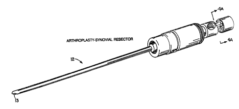
Figure 4 is a perspective view of a rotatable
surgical tool used with the handpiece shown in Figure 1
and connectable to the drive shaft shown in Figures 2
and 3.
Figure 4a is an enlarged perspective view,
partially cut away and in cross section, of the detail
area of Figure 4.
Referring to Figure 1 a cylindrical surgical
handpiece 10, has an outer housing 11, the length and
diameter of which are sized and textured to fit
comfortably into the palm of a surgeon. The distal end
of the handpiece 10 is adapted to receive a rotatable
surgical tool 12 (shown in dotted lines in Figure 1)
eg, an arthroplasty resector (shown in Figure 4). The
tool 12 engages a rotatable drive shaft 14 (shown in
dotted lines in Figure 1) which is bonded, for example,
by adhesive, to a rotatable motor shaft 16 extending
distally from a conventional electric motor 18 (the
motor shaft and the motor also shown in dotted lines in
Figure 1) into a recess in the drive shaft 14. This
bonding causes the drive shaft 14 to rotate with the
motor shaft 16 relative to the handpiece 10, in turn
rotating the tool 12.


6 ~~~~~.~;
Extending from the proximal end of the handpiece
10, a power line 20 connects the motor 18 to a power
source 22 ar other control device to regulate the
action of the tool 12, eg. its rotation speed.
Referring to Figure 4, the distal end of the tool 12
defines an opening 13 which communicates with proximal
portions of the tool. Thus, as shown in Figure 1, when
the tool 12 is connected to the drive shaft 14, eg. by
a flange 15 (shown in detail in Figure 4a? engaged in
the distal end of the drive shaft, fluid can flow from
a patient°s body through an opening in the cutter 13 at
the distal end of the tool and collect in a passageway
24 exposed to the drive shaft and motor housing.
Referring again to Figure 1, the passageway 24 is
defined by the open areas between the tool 12 and the
inner walls of the handpiece 10, and between the drive
shaft 14 and the inner wall of the handpiece. Most of
the fluid exits the passageway 24 through a port 26 and
a rotary valve 28 into a channel 30 connected to a
drain tube 32. Fluid in the channel 30 is then
suctioned through the drain tube 32 by a suction source
34 connected to the tube. Nevertheless, it is possible
for some fluid to remain within the passageway 24,
which presents a potential hazard should the fluid seep
into the motor Z8 and cause it to malfunction or


- ' ' ~~~~~~s
corrode. As described below in connection with Figures
2 and 3, the present invention provides an improved
sealing assembly to prevent fluid from reaching the
motor 18.
Referring to Figures 2 and 3, the handpiece 10
further contains a motor housing 36 which includes a
ring gear section 38, a ball bearing section 40, and a
shoulder section 43, which are pressed and swaged
together to form a 3-piece assembly. Adjacent to the
distal end of the motor housing 36 and surrounding the
proximal end of the drive shaft 14 is a seal assembly
44 which includes a static seal ring 46 and a dynamic
seal ring 48. The static ring 46 is rotationally fixed
relative to the motor housing 36 by a pin 50 that
extends from within the motor housing and fits into
a slot 52 cut into the proximal face of the static
ring. The static ring 46 is not otherwise attached to
the motor housing 36, but rather is held in place
against the motor housing by the adjacent dynamic ring
48 which rotates with the drive shaft 14.
Referring in particular to Figure 2, a pair of
silicone o-rings 53 seal between the static ring 46 and
the main housing 11 of the handpiece, to prevent fluid
from flowing past the motor assembly. In order that
the dynamic ring 48 may rotate with the drive shaft 14,


- 204~~ ~:
a cap ring 54 is screwed over a threaded portion of the
distal U-shaped end of the drive shaft I4, thereby
causing the cap ring to rotate with the drive shaft.
Adjacent to the cap ring 54 is a spring ring 56
captured between the cap ring 54 and shoulder 55
(Figure 3) of shaft 14 so as to rotate with the shaft.
Next, a drive ring 58 is rotatably connected to the
spring ring 56 by a tab 60 on the drive ring which fits
into a slot 62 eut into the sprang ring. Thus, the
drive ring rotates with the drive shaft 14. And
finally, the dynamic ring 48 is rotatably connected to
the drive ring 58 by a pair of tabs 65 (180° apart)
which fit into slots 65 in the dynamic ring.
Referring to Figure 3, in order to hold the
dynamic ring 48 and the static ring 46 together and
create a seal, a plurality of springs 66 (for example,
nine in total, each may be approximately 6.35mm (0.25
inches) in length, I.45mm (0.057 inches) in diameter,
and formed of I/4 free length 0.2mm (0.008 inch) wire)
are circumferentially spaced around the drive shaft I4
in holes drilled through the spring riag 56. The
spring 66 acts against the cap ring 56 and press the
drive ring 58, which is axially movable along the drive
shaft 14, toward the dynamic ring 48. Disposed around
the drive shaft 14, between the drive ring 58 and the
dynamic ring 48, is a buffer ring 68, erhich is


- ~ ~ ~~ e)
preferably formed of silicone rubber. The buffer ring
68 acts as a resilient interface between the drive ring
and the dynamic ring to insulate seal rings 46 and 48
from vibrations during operation of the device, and to
avoid direct contact between the metal drive ring 58
and the distal surface of the dynamic ring 48, all to
increase the operating life of the seal.
Referring still to Figure 3, the dynamic ring 48
surrounding the drive shaft 14 is sealed thereto by an
o-ring 70 disposed in a groove 71 formed in the drive
shaft, thus closing a secondary fluid leakage path to
the motor and maintaining a constant distance between
the drive shaft 14 and the dynamic ring 48 should the
drive shaft 14 begin to wobble, thereby helping to
preserve the seal formed between the mating portions of
the dynamic ring 48 and the static ring 46.
immediately adjacent to the o-ring, is a tapered
proximal end portion 14a of the drive shaft 14. The
tapered portion 14a is bonded as described above to the
distal end of the motor shaft 16 (shown in dotted
lines), thereby causing the drive shaft 14, and all
components described above as being rotatably connected
thereto, to rotate with the motor shaft 16 relative to
the handpiece 10. In addition, surrounding the motor
shaft 16, is a washer 72 which acts as a spacer between
the tapered portion 14a and the motor housing 36.


to - ~~~4~~~; r
More specifically, the mating portions of the
static ring 46 and the dynamic ring 48 form a face seal
76 in a plane perpendicular to the drive shaft axis 80.
Generally, the face seal 76 is formed toward the inner
edge of the static ring 46 because the proximal portion
of the dynamic ring 48, ie. that portion which makes
contact with the static ring 46, is stepped inwardly on
the surface of its outer diameter so that the mating
portion of the dynamic ring is approxiaately 1/3 the
width of the mating portion of the static ring 46.
Although the face seal 76 generally remains at the
inner edge of the static ring 46, it can sometimes
shift towards an outer edge of the static ring because
of a lack of rigidity or a side to side wobble in the
drive shaft 14. Nevertheless, the shape of the dynamic
ring 48 and its positioning relative to the static ring
46 allow the drive shaft 14 to wobble relative to the '
motor housing 36 without disturbing the face seal 76,
ie. the mating portion of the dynamic ring simply
slides radial.ly along the mating portion of the static
ring.
The dynamic and static rings 48 and 46 are
preferably formed of silicon carbide and a carbon
graphite composite, respectively. Also, in order to
provide as effective a face seal as possible, the


- 11 -
contacting faces of the dynamic and static rings 48 and
46 are polished to a very flat surface free of
scratches and grooves, eg. flat lapped within two or
three helium light bands. The solid materials chosen
are preferred over the more flexible materials used in
previous sealing arrangements, eg.
polytetrafluoroethylene or silicone rubber, because
they are not sensitive to the material or finish of the
drive shaft. Previously used materials were prone to
wear out quickly, in part because they contacted the
drive shaft itself, a disadvantage that the placement
of the rings in the present invention avoids. Finally,
the harder materials used in the present invention are
resistant to abrasives and other conta'inants in the
environment, thus ensuring a greater lifetime of use
for the motor 18.
The surgical device of the present invention
provides several advantages over previously known
surgical devices using o-ring or lip seal arrangements.
Most notably, an effective face seal is achieved
transversely to the axis of rotation of the drive
shaft, and the seal is maintained regardless of whether
the drive shaft wobbles. In addition, the materials of
the sealing elements are not prone to warp or wear out
quickly, nor are they likely to become contaminated.
lend finally, vibrations in the handpiece are reduced.


_ li _ ~~~9~~
In addition to the provision of handpieces as
hereinbefore described, the present invention also
provides a surgical device comprising a rotatable
surgical tool and a handpiece in accordance with the
invention which is adapted to receive and engage said
tool.
Tools for use with the surgical devices of the
invention include rotatable cutters and shavers
including, for example, the arthroplasty - surgical
resector shown in Figure 4 of the accoapanying
drawings.

Representative Drawing
A single figure which represents the drawing illustrating the invention.
Administrative Status

For a clearer understanding of the status of the application/patent presented on this page, the site Disclaimer , as well as the definitions for Patent , Administrative Status , Maintenance Fee  and Payment History  should be consulted.

Administrative Status

Title Date
Forecasted Issue Date 2002-03-19
(22) Filed 1991-08-15
(41) Open to Public Inspection 1992-02-18
Examination Requested 1998-08-14
(45) Issued 2002-03-19
Deemed Expired 2006-08-15

Abandonment History

There is no abandonment history.

Payment History

Fee Type Anniversary Year Due Date Amount Paid Paid Date
Application Fee $0.00 1991-08-15
Registration of a document - section 124 $0.00 1993-01-29
Maintenance Fee - Application - New Act 2 1993-08-16 $100.00 1993-07-13
Maintenance Fee - Application - New Act 3 1994-08-15 $100.00 1994-07-22
Maintenance Fee - Application - New Act 4 1995-08-15 $100.00 1995-07-20
Maintenance Fee - Application - New Act 5 1996-08-15 $150.00 1996-07-19
Maintenance Fee - Application - New Act 6 1997-08-15 $150.00 1997-07-24
Maintenance Fee - Application - New Act 7 1998-08-17 $150.00 1998-07-16
Registration of a document - section 124 $50.00 1998-07-21
Request for Examination $400.00 1998-08-14
Maintenance Fee - Application - New Act 8 1999-08-16 $150.00 1999-07-19
Maintenance Fee - Application - New Act 9 2000-08-15 $150.00 2000-07-18
Maintenance Fee - Application - New Act 10 2001-08-15 $200.00 2001-07-16
Expired 2019 - Filing an Amendment after allowance $200.00 2001-11-06
Final Fee $300.00 2001-12-19
Maintenance Fee - Patent - New Act 11 2002-08-15 $200.00 2002-07-16
Maintenance Fee - Patent - New Act 12 2003-08-15 $200.00 2003-07-17
Maintenance Fee - Patent - New Act 13 2004-08-16 $250.00 2004-07-19
Owners on Record

Note: Records showing the ownership history in alphabetical order.

Current Owners on Record
SMITH & NEPHEW, INC.
Past Owners on Record
SJOSTROM, DOUGLAS DANA
SMITH & NEPHEW DYONICS, INC.
SMITH & NEPHEW ENDOSCOPY, INC.
Past Owners that do not appear in the "Owners on Record" listing will appear in other documentation within the application.
Documents

To view selected files, please enter reCAPTCHA code :


To view images, click a link in the Document Description column. To download the documents, select one or more checkboxes in the first column and then click the "Download Selected in PDF format (Zip Archive)" or the "Download Selected as Single PDF" button.

List of published and non-published patent-specific documents on the CPD .

If you have any difficulty accessing content, you can call the Client Service Centre at 1-866-997-1936 or send them an e-mail at CIPO Client Service Centre.


Document
Description 
Date
(yyyy-mm-dd) 
Number of pages   Size of Image (KB) 
Claims 2000-12-21 4 95
Cover Page 1993-12-14 1 12
Description 1993-12-14 12 327
Drawings 1993-12-14 4 104
Abstract 1993-12-14 1 11
Claims 1993-12-14 4 93
Claims 2001-11-06 10 288
Cover Page 2002-02-21 1 32
Representative Drawing 2002-02-21 1 9
Representative Drawing 1999-04-20 1 32
Correspondence 2001-12-19 1 26
Prosecution-Amendment 2001-11-06 7 231
Prosecution-Amendment 2001-11-21 1 14
Prosecution-Amendment 2000-09-07 2 54
Prosecution-Amendment 2000-12-21 6 178
Assignment 1991-08-15 6 222
Prosecution-Amendment 1998-08-14 5 179
Prosecution Correspondence 1998-09-18 5 162
Fees 1996-07-19 1 69
Fees 1995-07-20 1 74
Fees 1994-07-22 1 82
Fees 1993-07-13 1 55