Language selection

Search

Patent 2049292 Summary

Third-party information liability

Some of the information on this Web page has been provided by external sources. The Government of Canada is not responsible for the accuracy, reliability or currency of the information supplied by external sources. Users wishing to rely upon this information should consult directly with the source of the information. Content provided by external sources is not subject to official languages, privacy and accessibility requirements.

Claims and Abstract availability

Any discrepancies in the text and image of the Claims and Abstract are due to differing posting times. Text of the Claims and Abstract are posted:

  • At the time the application is open to public inspection;
  • At the time of issue of the patent (grant).
(12) Patent: (11) CA 2049292
(54) English Title: UNSYMMETRICAL FREE PISTON ENGINE
(54) French Title: MOTEUR DISSYMETRIQUE A PISTON LIBRE
Status: Deemed expired
Bibliographic Data
(51) International Patent Classification (IPC):
  • F02B 71/00 (2006.01)
  • F01B 9/04 (2006.01)
  • F02B 71/02 (2006.01)
(72) Inventors :
  • BRAUN, ANTON (United States of America)
(73) Owners :
  • BRAUN, ANTON (United States of America)
(71) Applicants :
  • BRAUN, ANTON (United States of America)
(74) Agent: KIRBY EADES GALE BAKER
(74) Associate agent:
(45) Issued: 1999-09-07
(86) PCT Filing Date: 1990-01-23
(87) Open to Public Inspection: 1991-07-24
Examination requested: 1997-01-17
Availability of licence: N/A
(25) Language of filing: English

Patent Cooperation Treaty (PCT): Yes
(86) PCT Filing Number: PCT/US1990/000325
(87) International Publication Number: WO1991/011596
(85) National Entry: 1991-09-20

(30) Application Priority Data: None

Abstracts

English Abstract


A compact free piston engine of the unsymmetrical type
including a structure with a cylinder (11) detachably supported
therein, said cylinder having a pair of pistons (12 and 13) with a
combustion chamber (14) therebetween and each piston having
a rod (15 and 18) extending through the adjacent end of the
cylinder and having motion reversing means (20, 22, 23, 22a, 23a,
24, 25, 27, 28, 17) at one end of said cylinder and extending
between said rods. Preferably, the structure is of strong but
light-weight construction. It may have a skeleton type of housing (10)
with bolt type columns (110) spaced around the cylinder. Portions
of the reversing means (27, 28) lie along the side of the cylinder
while another major portion (20, 22, 23, 22a, 23a, 24, 25)
thereof lies beyond one end of the cylinder. An energy absorbing
device or devices may be connected to one only (18a) or to
each of the rods (18a, 118a), and each rod will be driven
simultaneously in an opposite direction to the other by both pistons.


French Abstract

Un moteur compact à pistons libres de type asymétrique comprend une structure dans laquelle est soutenu de manière amovible un cylindre (11) qui contient une paire de pistons (12 et 13) et une chambre de combustion intermédiaire (14). Chaque piston comprend une tige (15 et 18) qui s'étend à travers l'extrémité adjacente du cylindre. Des moyens de renversement de la direction du mouvement (20, 22, 23, 22a, 23a, 24, 25, 27, 28, 17) agencés à une extrémité du cylindre s'étendent entre les tiges. De préférence, la structure est résistante mais légère. Elle peut comprendre un logement (10) en ossature avec des colonnes (110) en forme de boulon espacées autour du cylindre. Une partie des organes de renversement (27, 28) sont situés le long du côté du cylindre, alors que la plus grande partie de ceux-ci (20, 22, 23, 22a, 23a, 24, 25) sont situés au-delà d'une extrémité du cylindre. Un ou des dispositifs d'absorption de l'énergie peuvent être connectés à une tige (18a) seulement ou aux deux tiges (18a, 118a), les deux tiges étant entraînées simultanément en sens opposés par les deux pistons.

Claims

Note: Claims are shown in the official language in which they were submitted.


-6-

Claims

1. A compact and substantially vibration free
engine of the unsymmetrical free piston type
for driving a compressor or other energy
absorbing device comprising: a cylinder,
support means for supporting one end only of
said cylinder, first and second pistons in
said cylinder with a combustion chamber there
between, the first piston having a first rod
extending through a first end of said
cylinder, the second piston having a second
rod extending through a second end of said
cylinder and having a double rack thereon
beyond said second cylinder end, a pair of
spaced pinion gears beyond said second end
with one each engaging one side each of said
double rack, a pair of spaced and rigidly
connected racks having one each of the
connected racks engaging one each of said
pinion gears, a drive shaft extending from one
of said first or second rods for driving an
energy absorbing device, and drive means
located along the side of the cylinder and
extending from said spaced racks to the rod
beyond the opposite cylinder end so that as
said pistons move apart each will exert a
force on said drive shaft in the same
direction.
2. An engine defined in Claim 1 wherein said
drive shaft is an extension of said second rod
beyond said double rack.
3. An engine as defined in Claim 1 wherein said
drive means is symmetrical with respect to the


-7-

axes of said first and second rods.
4. An engine as defined in Claim 1 wherein the
total mass of one of said pistons and the
elements connected thereto and movable
therewith equal the total mass of the drive
shaft and the piston and other elements
connected thereto minus the mass of the energy
absorbing device to be moved thereby.
5. An engine as defined in Claim 2 wherein a
second drive shaft extends from the other of
said rods beyond said yoke.
6. An engine as defined in Claim 1 wherein the
longitudinal axes of said cylinder and support
means are substantially coaxial.
7. An engine as defined in Claim 1 wherein said
support means is located at least partially
around said cylinder and includes a wall
extending transversely with respect to the
axis of the cylinder and to which said one end
of said cylinder is secured.
8. An engine as defined in Claim 1 wherein said
support means is in the form of a skeleton
type of housing.
9. An engine as defined in Claim 1 wherein said
support means includes a plurality of
structural members spaced around said
cylinder.
10. An engine as defined in Claim 7 wherein a
plurality of said cylinder, pistons and


-8-

driving means are supported from said wall.

Description

Note: Descriptions are shown in the official language in which they were submitted.


WO 91/11596 PCT/US90/0032~
~0492~~
-1 -
Description
UNSYMMETRICAL FREE PISTON ENGINE
Technical Field
This invention relates to an improved
combination of basically old elements in free
piston engines, such as shown in the inventor's
U.S.A. Patent No. 3,524,436. The new combination
makes it possible to reduce the overall weight of
the engine by providing a light weight cylinder
supporting structure and reducing the size thereof
as compared with prior art engines of equal
horsepower.,
The invention lies in a compact free piston
engine of the unsymmetrical type having a pair of
coaxial pistons in a cylinder, including a motion
reversing mechanism serving both as a synchronizing
and a driving mechanism for an energy absorbing
device. The speed of the engine is greatly
increased over what 1s accomplished in prior art
engines. This provides a highly efficient and
compact linear engine that permits the driving
mechanism to be external of the engine cylinder, to
have less weight and cost and to not require a
heavy housing construction. The invention further
provides for a less weight entire engine by
detachably supporting the cylinder at one end only
in a skeleton type structure which also renders the
cylinder pr a.liner therein, less subject to
deforming stresses.
Drawings
The preferred embodiments of the invention are
schematically illustrated in the drawing wherein:
Fig. 1 is a vertical sectional view of one
embodiment of the invention;


PCT/US90i00325
WO 91 / 11596 ~ ~ . , ~)
-2-
Fig. 2 is a similar view of the cylinder
supporting structure only of another embodiment of
the invention;
Fig. 3 is a sectional view of the embodiment
of Fig. 2, along line 3-3 of Fig. 2;
Fig. 4 is a fragmentary view of a modified
lower end of the engine of Fig. 1;
Fig. 5 is still another modification of the
invention suitable for horizontal mounting.
Description
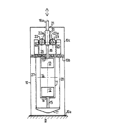
The arrangement shown, in Fig. 1 has a light
weight support or housing 10, preferably of
skeleton type construction and adapted to be
mounted on a base B with the longitudinal axis of
the housing extending vertically. A cylinder 11,
which is preferably coaxial with the housing, is
suitably suspended at its upper end on an~upper
end wall 10b of said housing,
First and second pistons 12 and 13 in the
cylinder have a conventional combustion chamber 14
there between. Piston 12 has a piston rod 15
extending through a bearing 16 in one end of the
cylinder and carries a yoke 17 at its outer end.
Piston 13 has a piston rod l8,extending through a
bearing or seal 19 in the other end of the cylinder
and carries a double rack 20 and a piston rod
extension 18a which, in turn, extends through a w
bearing or seal 21 in the upper end of the housing.
Pinion gears 22 and 23 are mounted on fixed
shafts 22a and 23a on opposite sides of the double
rack (20) and engage opposite sides of the double
rack. the shafts may be mounted on supports (not
shown) extending upwardly from the upper end wall
10b of the cylinder. A pair of spaced racks 24 and
35~ 25 engage gears 22 and 23, respectively, and are


1fO 91/11596 Z ~ ~ ~ ~ y ~ PCT/L'S90100325
-3-
rigidly connected by a pair of plates 26 (one
shown) with the gears 22 and 23 there between.
Racks 24 and 25 are connected to the yoke 17 by a
pair of symmetrically located rods 27 and 28 lying
between the cylinder and the housing structure.
Oil is sealed in an upper portion 10c of the
housing and preferably is pumped, by external means
not shown, from the sump to and over the gears and
racks. It is to be understood that the yoke could
be a compressor piston, scavenge piston or bounce
piston.
Operation
With the engine connected to an energy
absorbing device, such as a compressor with a
piston having a weight which, when coupled with the
weights of connecting elements 18a, 20, 18 and 13
of the engine, equals the combined weights of the
appositely moving weights 24, 25, 26, 27, 28, 17,
15, and 12, the engine~will operate in a highly
efficient and substantially vibration free manner.
The engine is started by suitable conventional
means that introduces fuel and air into the chamber
14, drives the piston towards the center of the
cylinder and then ignites the fuel-air mixture.
Outward movement of the pistons 12 and 13 causes
tension to pull the reversing racks so as to drive
gears 22 and 23 to move double rack 20 in the same
direction as does piston 13.
The modification of Figs. 2 and 3 differs from
the Fig. 1 engine in that it is a more detailed
showing of the cylinder and its supporting
structure. Spaced rods or bolts 110 are screw
threaded into base llOa and bolted at their upper
end to support plate 110b, replacing the skeleton
type of housing 10 of Fig. 1. This construction


V1'O 91 /11596 PCT/US90/0032:
-4-
can be of less weight and less manufacturing cost
and more suitable than that of Fig: 1 for applying
sound insulating material around the cylinder, if
desired. Also, the bolts may be replaced by other
structural elements serving the same function.
The operation of the modification of Figs. 2
and 3 is the same as that of Fig. 1. The rods
provide the same supporting function for the
cylinder as the housing 10.
The embodiment of Fig. 9 is the same as Fig. 1
except for the substitution of a compressor piston
217 in a scavenge air cylinder 210 for the yoke 17
in Fig 1. The scavenge air chamber has an inlet
check valve 218 and an outlet check valve 219 for
delivering scavenge air to the combustion chamber
14 through a conduit 220. However, the piston 217
also serves as a yoke to actuate the spaced racks
of the reversing mechanism through rods 227 and
228.
The operation of the embodiment of Fig. 4 is
otherwise the same as that of Fig. 1.
The embodiment of Fig. 5 is the same as that
of Fig. 1 except for being adapted to be mounted
horizontally on its supporting base 310a and having
. a drive shaft 18a and 118a extending, respectively,
out of opposite ends of the housing 310. This
arrangement enables the drive shaft at one end to,
for example, actuate a first stage compressor
piston and a third stage compressor piston and the
other drive shaft to simultaneously actuate a
second stage compressor piston and a fourth stage
compressor piston and have the various units driven
by the engine readily assembled and accessible or
disassembled for servicing.
Here, again, the operation of the engine in
Fig. 5 is the same as that of Fig. 1.


1~ C> 91 / 11596 ~ ~ ~ ~ ~ ~ ~ PCT/L.'S90/0032~
-5-
Another modification, for example, is one
wherein a plurality of cylinder and driving
mechanism assemblies are suspended from a single
support structure with a common enclosure which
results in a machine of substantially less cost and
weight and small size. Also, it provides a common
set of auxiliary equipment and accessories for all.
cylinders, such as, for example in a six cylinder
version of such a multi-cylinder unit, only one
common cooling system and a single starting unit in
place of six individual ones. An obvious advantage
of such a multistage cylinder unit over a crank-
driven equivalent is that in the crank type multi-
cylinder engine, even if only one cylinder is
defective, the whole engine is incapacitated,
whereas if any one or more of the cylinders in a
multi-cylinder unit of the present invention fails,
all of the remaining cylinders will still be fully
available. This feature also makes it possible to
schedule sequential servicing of the individual
cylinders to increase the availability of such a
machine to practically 100 %.

Representative Drawing
A single figure which represents the drawing illustrating the invention.
Administrative Status

For a clearer understanding of the status of the application/patent presented on this page, the site Disclaimer , as well as the definitions for Patent , Administrative Status , Maintenance Fee  and Payment History  should be consulted.

Administrative Status

Title Date
Forecasted Issue Date 1999-09-07
(86) PCT Filing Date 1990-01-23
(87) PCT Publication Date 1991-07-24
(85) National Entry 1991-09-20
Examination Requested 1997-01-17
(45) Issued 1999-09-07
Deemed Expired 2002-01-23

Abandonment History

Abandonment Date Reason Reinstatement Date
1998-01-23 FAILURE TO PAY APPLICATION MAINTENANCE FEE 1998-02-17

Payment History

Fee Type Anniversary Year Due Date Amount Paid Paid Date
Application Fee $0.00 1990-01-23
Maintenance Fee - Application - New Act 2 1992-01-23 $100.00 1992-01-22
Maintenance Fee - Application - New Act 3 1993-01-25 $100.00 1993-01-07
Reinstatement: Failure to Pay Application Maintenance Fees $200.00 1994-07-20
Maintenance Fee - Application - New Act 4 1994-01-24 $100.00 1994-07-20
Maintenance Fee - Application - New Act 5 1995-01-23 $150.00 1995-01-18
Reinstatement: Failure to Pay Application Maintenance Fees $200.00 1996-02-09
Maintenance Fee - Application - New Act 6 1996-01-23 $75.00 1996-02-09
Maintenance Fee - Application - New Act 7 1997-01-23 $75.00 1997-01-13
Reinstatement: Failure to Pay Application Maintenance Fees $200.00 1998-02-17
Maintenance Fee - Application - New Act 8 1998-01-23 $75.00 1998-02-17
Maintenance Fee - Application - New Act 9 1999-01-25 $75.00 1999-01-21
Final Fee $150.00 1999-06-02
Maintenance Fee - Patent - New Act 10 2000-01-24 $300.00 2000-02-01
Owners on Record

Note: Records showing the ownership history in alphabetical order.

Current Owners on Record
BRAUN, ANTON
Past Owners on Record
None
Past Owners that do not appear in the "Owners on Record" listing will appear in other documentation within the application.
Documents

To view selected files, please enter reCAPTCHA code :


To view images, click a link in the Document Description column. To download the documents, select one or more checkboxes in the first column and then click the "Download Selected in PDF format (Zip Archive)" or the "Download Selected as Single PDF" button.

List of published and non-published patent-specific documents on the CPD .

If you have any difficulty accessing content, you can call the Client Service Centre at 1-866-997-1936 or send them an e-mail at CIPO Client Service Centre.


Document
Description 
Date
(yyyy-mm-dd) 
Number of pages   Size of Image (KB) 
Cover Page 1994-03-12 1 13
Claims 1994-03-12 3 69
Drawings 1994-03-12 1 32
Abstract 1995-08-17 1 58
Description 1994-03-12 5 186
Abstract 1998-09-16 1 49
Cover Page 1999-08-31 1 55
Representative Drawing 1999-08-31 1 5
Correspondence 1999-06-02 1 41
Fees 1998-02-17 1 50
Fees 2000-02-01 1 54
International Preliminary Examination Report 1991-09-20 1 57
PCT Correspondence 1992-01-22 1 44
Prosecution Correspondence 1997-01-17 2 97
Office Letter 1992-05-14 1 12
Fees 1997-01-13 1 71
Fees 1996-02-09 1 54
Fees 1995-01-18 1 76
Fees 1994-07-20 1 48
Fees 1993-01-23 1 23
Fees 1992-01-22 1 22
Correspondence 1995-03-08 1 21