Note: Descriptions are shown in the official language in which they were submitted.
WO 90/12~91 P(~/GB90/00'177
33 ~ ~
INK JET NOZZLEJVALVE . PEN AND PRINTER
The present invention relates to ink jet nozzles for
use in ink jet printers or writing instruments such as
pens. More particularly, as concerns printers, the
invention relates to ink jet printers of the drop~on-demand
t~pe in which ink droplets are! selectively emitted under
pressure through a row of nozz;Les.
It is Xnown for a series of solenoid val~es to open
and close the plural nozzles selectively so that an ink
droplet is only emitted from a nozzle when a dot is
required to be printed. Such a printer is described in
GB-B-2134452.
However, a wide range of valve operated drop-on demand
printers exists, one type which uses solenoid operated
valves being used to print relatively large characters. It
has also been proposed to use valve actuators comprising
piezoelectric materials, operating plungers, cantilevered
closure arms or the like for example. O~ice printers may
be of the open orifice type in which ink is ejected by a
hydraullc pressure within the ink. This may be generated
by a piezoelectric diaphragm or by localised heating of the
ink.
High speed ink jet printers are usually of the so
called "continuous type" in which a stream of ink droplets
is continuously emitted from a nozzle, the droplets which
are to be printed being charged and then deflected to a
chosen print position by electrostatic forces, and droplets
~hich are not required to be printed passing directly to a
gutter and being recirculated. The control mechanisms for
such continuous ink jet printers are there~ore complicated
and, as a direct consequence, the selling price of a single
printhead continuous ink jet printer i5 very high in
comparison with that of a drop-on-de~and printer. HoweYer,
such printers are typically used to produce small
characters or rows of character~ generally less than about
5mm in height. Increasin~ the number o~ nozzlP~ in order
'
-
,
,
.' - , : . :
WO90i12691 pcr/cB9o/oo477
3~L5
to produce larger characters, inevitably ~urther
complicates the control mechanism.
There is a need therefore for an ink jet printer which
is capable of being used to pr:int small, medium and large
characters using the same technology, in oxder to enable
the bene~its of modularity to he achieved and to enable a
single control system to be use~l across a range of printers
using different size characters. It is also desirable that
a single printer be usable to print characters o~ different
sizes.
Although the ability to print characters of different
sizes can, in part, be achieved by means o~ continuous ink
jet printers, the range of sizes is strictly limited.
Other attempts at allowin~ variable sized characters to be
printed have been made using drop-on-demand printers by
allowing the nozzle assembly to be adjusted in position
relative to the material in which the characters are
required to be printed, in order to change the angle at
which ~he droplets impinge on the material and thus alter
the height. However, again, the size of the characters
which can be printed using such techniques is strictly
limited.
A variety of means aFe employed in the construction of
pens and similar writing instruments for depositing ink on
the writing surface, but a general requirement is that a
fine and uniform line be produced with great consistency
and low writing press~re.
The present invention has the ob~ect of providing a
nozzle which is usable in both printer~ and pens to provide
the partic~lar requirements of both.
According to the invention, there is provided a nozzle
for an ink jet printer or writing instrument, the nozzle
being formed by an orifice in an elastic material, and the
orifice comprising a slit or hole in the elastic material,
deformable to cause the slit or hole to open or close.
Further according to the invention, there is provided
an ink jet printer having an ink ch~mber for containing
- . . . . . . .
. .. , - . - .. . . :. , . :
. . : -: : . . : - , , :
.: - . . ~ , . . - . ~ : .
:. .. - ~ . . : . :
~- : :: : . -
.
WO90t12691 PCT/CB'~0/00477
t3~3 ~ ~5
ink; a closable orifice in a wall o~ the chamber, through
which a jet of ink is issued in use for printing on a
surface, the orifice being formed by a slit or hole between
an elastic material forming at least a portion of the
chamber wall and a ri~id oppos,ing surface; and an actuator
engaging the elastic material and operable to cause it to
d~form so as to open or close the slit or hole.
The ink chamber may be p:ressurized, for example from
an ink reservoir which is itse!lf put under pressure by say
an air-pressurised diaphragm, but other methods of
pressurizing the chamber may be employed. The ink chamber
may be self-pressurizing in use as a result o~ the
deformation of the chamber walls.
Preferably, the actuator i5 a piezoelectric
transducer, more preferably, a unimorph type piezoelectric
element.
The orifice may be formed by piercing the elastic
material from which the wall of the chamber is made, ox by
moulding it around an appropriate ~ormer, the puncture or
aperture being in the form o~ a slit or hole or system of
slits or holes. The slit or hole in the elastic material
effectively forms a val~e which can be operated by lateral
expansion or compression of the portion of the elastic
material around the slit.
25Preferably the orifice in the elastic material is
tapered to reduce loss of head through viscous drag
effe~ts, the minimum cross-section o~ ~he orifice being
provided at the outer sur~ace o~ the elastic matarial and
the profil2 of the taper ~eing designed appropriately.
30If a linearly tapering slit or orifice is used then,
because of the law of conservation of mass, the mean ink
velocity through a given section of the orifice will be
proportional to the cross-sectional arèa, and assuming
similarity of cross-section the velocity will be inversely
proportional to the square of the slit width. Since
viscous drag is proportional to the velocity gradient which
: in turn is inversely proportional to slit widthj the
- ~ . . ,
- .
., . , ~ ,
. . : : : . . :: .
: , .. .. . .
. . .
.: : . , . :
.
WOgO/1~691 pcr/c;B~n/oo~77
;2C9~''3~
incremental loss oP pressure will be inversely proportioned
to the cube of the slit width and the pressure distribution
along the slit will therefore follow a quarkic law which
may effectively limit loss of head to within a ~ew slit
widths of the orifice. This e~ect can be exaggerated if
required by use of a higher order curvature o~ the taper so
that a tapered elongate orifice through a thick elastic
wall may provide a lower pressure loss than a parallel
sided orifice through a thin membrane. Furthermore, the
~o thic~ness of the barrier may be used to provide the
rigidity required for directiclnal control o~ the jet and
the space to incorporate the actuator. The length of the
orifice may also assist in establishing stable jet flow.
A system of slits in an elastic material may
conveniently be produced hy transfixing the material
against a thin elastic substrate mounted on a rigid base,
with a pointed blade o~ appropriate taper. A single or two
edged blade, ~or example, may be used to provide a planar
slit and a three facetted point can provide three planar
slits intersecting along the axis of the orifice. The
diameter of the orifice can be controlled by the depth of
penetration of the piercing blade through the elastic
barrier and this can be achieved by appropriate çhoice of
blade sharpness, penetration depth, material thickness and
2S elastic modulus. Very fine orifice dimensions may be
produc~d with great consistency therefore.
To provide a slit between an elastic material and a
rigid surface the sur~ace may ba coated with a release
agent at the appropriate location and the elastic material
bonded to the sur~ace except where coated. Alternatively,
th~ elastic material may be pierced with a blade of
asymmetric cross-section such that the cutting device
automatically tends towards the rigid surfacs when
producing the slit.
3~ In order to open and close the orifice a variety of
means may be used, but radial or planar compression in the
plane o~ the elastic material around the orifice will cause
- :- .
- : :
.
. .
. . . . . ~ . .
WO90/1~691 2~3 ~5 PCT/GB90/00477
the orifice to close and expansion will open it, thus
providing, in e~fect, a valve to control ink ~low.
Compre~sion may be applied directly ko the la~eral
aspects of the orifice with a simple push pull transducer
system, but, alternatively, the ink pressure may be allowed
to distend the elastic material as a deflected beam, bridge
or plate, so producing compression of the slit. In this
fashion the closure pressure can be related direc~ly to the
ink pressure and by correct choice o~ geo~etry may always
be arranged to significantly exceed ink pressur2. The
orifice may be opened by applying an opposing pressure to
create tension across the slit: and it may be arranged to
open from the inner aspect of the orifice and close from
the outer aspect. This e~fect can be significantly
enhanced by providing the appxopriate profile to the
elastic material wall.
The inner surf~ca of the wall may be ridged or domed
around he orifice or orifices so that it effectively
hinges from the periphery of the ridge or dome. This
geometry may provide additional mechanical advantage for
ink pressure to close the valve.
A number of advantages result from a printer according
to the present invention. Firstly, the orifice is
positively closed when it is not pas~ing ink and this will
prevent or reduce the drying of ink in the ori~ice and
clogging of it with ink pigment. Secondly, since the jet
opens from the inside to the outside, and because a taper
may be provided to ensure low viscous losses, the full
driving pressure is substantially instantly available at
the orifice when the printer is switched on. This is
significant, ~or a low ink flow rate will produce over~low
which generates an ink drop on the outer face of the
elastic wall which obscures the ori~ice. This drop not
only impedes the ~ormation of a stable jet, but may also
influence the initial direction of the jet or even inhibit
jet formation entirely. Because of the tapering section o~
the slit it is possible to set up conditions whereby
.
.
` . ~ .
- -: ,
- .
'' ,
,
::
WO90/126~1 PC~/GB~0/0047/
initial ink flow into the open slit results in the
formation of a shock front. The surge of pressure
resulting from the shock front, at the opening of the
orifice, may ensure a clean start to the jet and assist in
clearing debris that may have accumulated - by distension
o~ the slit. The positive closure of the valve provides a
high pressure to exude remaining ink from the slot. The
termination o~ the jet may therefore be arranged to be as
precise as initiation and there will be no gradual
reduction in flow producing a residual ink drop on the
outer surface of the wall around the orifice.
one or more orifices may be provided in a single
elastic wall, with a corresponding number o~ respective
actuators or plural ori~ices with a single actuator - eg
for bar code printing.
Examples of printing devices constructed with nozzles
in accordance with the present invention will now be
described with reference to the accompanying drawings in
which:-
Figures 1, 2 and 3 illustrate cross-sections through
a nozzle;
Figure 4 illustrates a printer printhead in plan view;
Figure 5 illustrates the printhead in cros~-section;
. Figure 6 illustrate~ a second printer printhead in
plan view;
Figure 7 illustrates the second printhead actuator
assembly;
Figure 8 shows an embodiment o~ a pen using the nozzle
of the invention;
Figure g shows a third printer printhead in
cross-section;
Figures lOA,B,~ ~ illustrate the cycle of operation of
the third printer by reference to cross-sectional views;
and,
Figure ~.1 is a plan view of ~he third printhead on
s~aller scale.
- , . ,
.
-
:
WO~0/12691 ~ ~¢~ PCT/C,~()/004~7
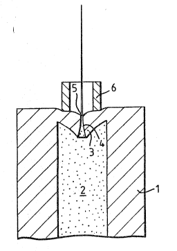
An embodiment of an ink jet pri.nter, with valveclosure by ink pressure, is shown in orthogonal sections
through the printhead axis in Figures 1 and 2. The rubber
component, 1, comprises a ri.gid cylindrical section
containing the pressurised ink, 2, and integral co~ical end
plug, 3. This is transected by a linearly tapering slit,
4, the outer aspect of which forms the ~riPice, 5. A rigid
ring-like component forms the act:uator, 6. Without load on
the actuator, ink pressure forces the conical end plug to
dish outwards, so sealing the slit. Pressure on the
actuator against the end plug causes tension on the conical
inner face which results in opening o~ the slit system.
The opened slit is illustrated in Figure 3. AlternativPly,
the actuator may be driven by magnetic elements or, whe~
used in a pen, manually.
There are a number of embodiments appropriate for
automated use, the exact design depending on the form of
actuator used. Figures 4 and 5 illustrate a longitudinal
and transverse section respectively through a printhead
having an array of nozzles.
The rubber component 7 connects with a pressurised ink
feed ~ and contains an array of nozzles in the form of
tapared slits 9. The slits may conveniently be formed by
transfixing the rubb~r componant with a comb of piercing
blades introduced through the ink feed 8.
Figures 4 and 5 illustrate a longitudinal and
transvers~ section respectively through a printhead having
an array of noz~les.
The printhead has a main body part 11 which may be
formed, for example, o4 bra~s, the body part 11 being
shaped so as to provide a -large recess to form an ink
chamber 8 and a smaller recess for~ing an extension 8'
leading to a plurality of nozzlPs 9 in the ~orm of tapered
slits provided in an elastic (for example rubber or other
elastomeric) component 7 which closas the end of the
extension 8'.
.
~ . .
WO90/12~l P~r/~0/00477
3~
A plurality of piezoelectric actuators 10 are disposed
along the length of the body part 11, each actuator
comprising an elongate piezoelectric ceramic layer 12
disposed on a metallic backing element 13. To close the
chamber 8 a rubber seal 14, ~or example, may be provided
across the top of the piezoelectric actuators. The rubber
seal is not shown in Figure 4. Alternative methods of
sealing the chamber 8 may be used.
In the example shown, the nozzle spacing is
approximately .25mm and the length of the piezoelectric
actuator about 7mm. The rubber component 7 has a thickness
of lO~m. The printhead is assembled with a preload so that
rubber component 7 is compressed by about 5~m. This
ensures that the slit valves are positively closed in their
quiescent state. Changes in dimension of the printhead due
to thermal expansion and solvent swelling or creep of the
rubber can be accommodated so as to maintain the nozzle
slit 9 closed under normal circumstances. The
pie~oelectric actuators have a displacement at-the noz21es
of about 30~m which therefore enables an effective opening
of about 20~m in the rubber nozzles when operatedO
It will readily be appreciated that a large number sf
nozzles can be accommodated in a very short length and it
is envisaged that nozzle spacing may be as low as O.lmm.
Individual piezoelectric actuators 10 are connected to
an electronic control so as to open and close individual
slits under microprocessor control in accordance with an
appropriate operating strategy.
Figures 6 and 7 illustrate a longitudinal and
transverse section respectively through a second printhead
having an array of nozzles.
The rubber component 7 contains an integral
pressurised i.nk feed 8 and an array of nozzles in the form
o~ tapered slits 9. The slits may be formed by transfixing
the whole component with piercing blades and then sealing
those through the end wall with appropriate adhesive. The
actuator 10 is in the form of a spring clip bonded to the
.
. - ~ . .
: ' . . ' ' : .
WO90tl2691 ~ 5 PCrtC~o/OO-t7,
rubber component. The natural spring c~upled with ink
pressure generates compression to hold the valve closed.
Energising the coils ll generates magnetic forces via the
yokes l2 which open the sprin~ clip and henc~ th~ nozzle.
Plural clips are provided, one in respect of each
orifice/noæzle.
In the embodiment of the pen shown in Figure 8, the
ink is pressurised by a propelling agent which may take the
form of gas dissolved under pressure in the ink or a
solution of a low boiling point fluid in the ink. The
solution of propellant in the ink ~ay be retained in a
porous element within the pen which connects hydraulically
to the valve by capillary action. In this fashion leakage
will probably avert spillage of ink and should result just
in loss of propellant. Alternatively, the pressurising
agent may be a low boiling point liquid floating on top of
the ink, incorporated in an open cell sponge insert that
preferentially absorbs the propellant. A further
alternative is physical separation of the ink and a
propelling fluid by a movable piston.
Figur~ 8 shows the pen as a sagittal section through
the axis of s~mmetry. The pen barrel lOl contains ink 102
pressurised by a low boiling point liquid 103 contained
generally by a rubber piston lO~. A rubber component 105
is inserted into the barrel lOl to seal th~e system and
provide the orifice/nozzle assembly. The pen barrel lOl
slides over the rubber component 105 providing radial
pressure ~hich keeps the orifice hole 107 closedO Pr~ssure
on the metal actuator 108 oauses the sealing membrane to
recede, so opening the orifice. The opening occurs from
the inner surface outwards, thus providing full pressure at
the orifice from the initial moment of opening.
Conversely, the orifice/nozzle closes first fro~ the
outside, inhibiting the formation of any droplets of ink on
the outer surface.
.
WO90/126()1 P~ 9"/00477
The third printhead illustrated in Figures 9 through
ll is similar in construction to that o~ Figures 4 and 5
and the same reference numerals are used where appropriate.
The printer body ll has a non-pressurised ink feed 8
with a plurality (in this example 128) ink channels 8'
which are formed between the body ll and respec~ive InYar
backing strips 13 on which piezoelectric ceramic unimorph
elements 2 are mounted. A ru]bber closure component 7 is
disposed at the end of the channels 8' to normally close
the channels, the component 7 having an array of 128
nozzles in the form of tapered slits 9. The slits may
conveniently be formed by trans~ixing the rubber component
with a comb of piercing blades introduced through the ink
feed 8 or ~rom the exterior.
The body part ll may be formed, for example, of brass,
being shaped so as to provide a large recess to form the
ink chamber 8 and smaller recesses forming the channels ~'.
In the example shown, the nozzle spacing is
approximately .25mm and the length of the piezoelectric
actuator about 4mm. ~he rubber component 7 has a thickness
of 50~m. The printhead may again be assembled with a
preload so that the rubber component 7 is compressed
appropriately.
Conveniently, a sandwich of slotted unimorph, piercing
comb and printer body, may be impregnated with raw rub~er
which is then cured to form, in on operation, the channels
with taper~d ends, the hydraulic seals between actuators,
isolating rubber walls between adjacent inX channels, and
electrical insulation around ~he actuator~. ~ubsequent
external pressure may cause the cutting tips of the
piercing comb to transfix the outer wall to produce the
array of ori~ices. The unimorph may su~sequently ~e ~onded
to the body with such a clearanee as to provide the
required residual compressive stress in the rubber.
As shown in Figure ll, individual pie~oelectric
actuators l9 are connected in groups to an electronic
control provided in part by a plurality o~ serial to
.
- . . . . . . ............. ..
, . . , ~ . - : ~ . :
. ,,. . , :, . : - .
WO90/1~691 z ~ g~ PCr/CB~)0/0~477
parallel inteyrated circuit driver chips 15 so as to enable
individual slits to open and close under microprocessor
control in accordance with an appr.opriate operating
strategy. By thi~ means a single low voltage data line may
drive the plurality of actuators, so removi~g the necessity
for a very ~ine pitch, high voltage multi way c~nnector.
The chips 15 are provided with appropriate inputs through
edge connectors 16 as shown.
As figures l0 A-C show, the cycle of operation of an
individual slit 9 starts with activation of the
piezoelectric unimorph 12 which rises and draws ink 17 into
the respective channel a~ from the ink feed chamber 8. The
reduced pressure ensures that the slit 9 remains clos~d.
The unimorph is then permitted to return so that the
inrushing ink is decelerated to provide positive hydraulic
pressure which opens the slit 9 and ejects ink from the
nozzle. As the pressure drops, the nozzle closes to cut
the flow of ejacted ink 18, Cessation of ~low occurs while
the ink is still under signi~icant pressure so that there
is a clean cutof~ with all the ejected ink travelling at
virtually the same velocity. The unimorph then returns to
its rest position.
The unimorph performance depends critically on the
rigidity of the unimorph/Invar bond to shear stress. Most
good adhesives are based on organic pol~mers which are
fundamentally less rigid than the unimorph components. One
solution to this problem is to roughen the glued ~urfaces
and include within the adhesive an ahgular riyid powder of
controlled grain size. Grains of the powder can loca e
within the roughness of the surfaces and jam under sh~ar
stress to provide a bond rigidity comparable with the
included powder. The adhesive then serves just to hold the
powder granules in place.
Due to the incompressibility of the ink, a small rapid
de~lection of the actuator may produce very high ink
pressures. A volumP o~ inlc comparable with the volume
displaced by the ac~uator will be exuded from the slit or
.~. . - - . ,- : :
. . . : . . .................. -
: ..... . ' ' . ' . :
woso/12691 pcr/cB~)o/oo477
Z 0 4 ~ 3 .,~
12
nozzle. Some of this displaced ink will open the valve and
the valve may be opened through a larger displacement than
khe maximum transducer displacement. The system therefore
acts as a hydraulic magni~ier.
5Initial actuation of the unimorph to enlarge the slot
8' provides higher hydraulic pressures and greater ink
displacement through the nozzle than simply depressing the
unimorph to produce a pressure impulse. This advantage may
be exploited by reducing the excitation voltage for lower
power consumption or by reducing the unimorph length for
higher frequency operation.
The rubber valve/nozzle may be formed externally to
the unimorph/printer body assembly. This confers greater
flexibility on the valve, eases the manufacturing
tolerances and permits a modicum of solvent swelling of the
rubber without unduly changing the mechanical
characteristics of the assembly.
: ~ .' .: : : ' ,: ~ . - ' ' ", .' "' "' , , "- ' ' '
. .