Note: Descriptions are shown in the official language in which they were submitted.
Z~33~9
Plallt growinq and cultivation system
The ~resent invention relates to a system for growing and
cultivating plants, comprising a plant table, plant boxes
arranged in the table as well as a drainage system for sur-
plus water and condensing water from the plant boxes.
In man~ situations it is nGt possible or not suitable to
grow plants on the ground level. Many old people, disabled
and particularly those bound to their wheelchair, are not
able to manage a planting efficiently on the ground level.
~hen plants today are cultivated and grown indoors to be
planted outdoors later on, various types of boxes and the
like are used, which are placed on tables, benches or the
like. Frequent nroblems with the watering, the runoff of
surplus water as well as the soil cultivation occur.
In e.g. public buildings it is often difficult and expensive
to make alterations in a flower or plant arrangement with
lower boxes.
The object of the present invention is to suggest a plant
gro~;~in~ svstern of the type mentioned by way of introduction,
which is versatile and allows growing indoors as well as out-
doors, which allows working in a sitting position at~the
table e.g. in a wheel chair and whicn allows fast altera-
tions or exchanges of flower arrangements and the like de-
per.ding on the wishes.
This is attained by-means of the system according to the pre-
sent in,vention, which is characterized in that the table is
constructed with mutually connected profiles, provided with
bearing supports for soil-carrying plates or boxes, mounted
in the table, which bearing supports include elements, which
fo.~rn channels, and in that the soil-carrying boxes orplates
are provided with drainage holes, designed to be placed above
33~L~
said channels.
An additional object of the invention is to suggest a table, which can
be built with modules, designed to be placed against a wall or in a
corner or round a corner. Said modules suitably are mainly piece of
ca1ce--shaped sectors. Thus, a preferred embodiment of the table is
characteri-~ed in that the table is subdivided in-to sectors by means of
partit~ons, which form a first bearing support, which partitions
extend like a fan from a table corner or from the center of a long
side or like spokes from the center of the table, as well as in that
border elements, which form second bearing supports, connect the outer
ends of the partitions in order to make them jointly form the border
of the table. Each sector suitably has a central angle of 45, the
table p.eferably comprising two such sectors in order to constitute a
table in a corner, four sectors to constitute a table, which can be
attache~ to a wall, six sectors to consti~ute a table, which extends
round a corner or eight sectors to constitute a table having an outer
regular octagonal shape.
In case the external shape of the table is a regular polygon, possibly
rounded to lorm a circle, the table preferably is rotatably mounted on
a central support with a hub rotatably mounted on the support. Said
first bearing supports are elements on partitions comprising spoke
prof~les, which extend radially outwards fro,n the hub in such a way,
thal. they subdivide the table into said sectors, said second bearing
supports comprising clements on border profiles, which connect the
outer ends of the spoke profiles in order to jointly constitute the
border of the taole on all sides.
The above-mentioned channels primarily comprise said first bearing
supports, at least one drainage opening or passage being disposed in
or in connection with each such channel adjacent the center of the
table, or acjacent the starting point for said fan-shaped outwardly
directed partitions, respectively, each such channel having a
93~L~
sufficient volume in order to be able ~o drain off surplus water from
said drainage ho~es in the boxes or plates towards said drainage
openin.G or passage.
Said second bearing supports, which are elements on the border of the
table, pr2ferably also constitute channels, which are ~ble to collect
surplus water from said drainage holes in said plates or boxes, these
channels in said second outer bearing supports communicating with
those channels, which constitute the first bearing supports, in such a
way, that water which has been collected adjacent the border of the
table also will be drained off towards the center of the table or a
corresponding point via the channels in the radial or fan-shaped
bearing supports.
From what has been stated above one can draw the conclusion that the
sectors suitably are triangle-shaped and that the central angle of the
sector preferably is 45. In each triangular sector one or several
plant boxes can be put, which preferably are uniform with the sector
triangle. By giving the plant boxes such a shape, that four triangular
plant boxes with fit can be disposed in each sector, and by providing
each plant box with a bottom hole in each corner, each~such hole can
be placea,above a channel in any of said first and second bearing
suppo~ts.
The ta~-.le suitably is open below the plant boxes in such a way, that
air can pass througil the table in passages between the plant boxes.
This is particularly advantageous in case the table is covered with a
light-penetrab~e superstructure in order to obtain a mini-greenhouse.
Since the bottom of the greenhouse obtained in this way is provided
witn air passages, a satisfactory change of air can be achieved
without loosing the desirable greenhouse-effect.
Provided it is desirable, in said plant boxes several small
3~
plant containers, e.g. four small containers in each large
container, can be put. Thus, in case the table comprises
eight sections, each containing 32 plant boxes, a total
number of 128 small boxes can be housed, four small boxes
be ng placed in each one of the large plant boxes.
rhus~ in its preferred embodiment the system according to
the inv~ntion includes a table, which is subdivided into sec-
tors bY means of spoke profiles, designed with bearing sup-
port:s as well as a border on all sides, which also is de-
sicJned with bearing supports for plant boxes, said bearing
supports also being used as drainage channels, which end
against a central pole or the like, where the water either
can flow along the central pole (for use outdoors) or be col-
lected (for use indoors). That the system has loose plant
boxes and drainage channels means that no floor, by means of
whicll the boxes can be supported, is needed, which results
in an excellent ventilation effect, fresh air all the time
pene-trating from below.
~ccorcling to the preferred embodiment the boxes are suppor-
ted by the bearing supports, designed as drainage channels,
having three corners and two complete sides. The system is
built in such a way, that all the boxes lock each other and
that the boxes cannot fall out from their bearing supports
even if one box is removed from the system, despite the fact
tha~ there is no covering bottom between the bearing sup-
ports.
Tll case the plant table, in accordance with a preferred em-
bodiment, is provided with a central axis, the plant table
can ke rotatably mounted about its axis. This is important
to old people and/or handicapped persons, who can push their
wheel chair into a position below the table and reach all of
the plant boxes, when they start revolving the table.
~ddi~ional characterizing features and aspects as well as
33~
advantages of the present invention will be set forth in
~he followin~ patent claims and the followin~ description
of a few preferred embodilllents.
srief description of the drawings
In the following description reference will be made to the
accompanying drawings, in which:
Fig. 1 is a perspective view of a preferred embodiment of a
self-supporting table having a central support and a roof
made of a transparent material, illustrating how the plant
table is to be used;
Fig. 2 shows the same plant table from above without any
roof and with empty plant boxes;
Fig. 3 shows the plant table accordi~g to Fig. 3 in a per-
spective view from below, the plant boxes being removed;
Fig. 4 is a partial view from above of the attachment bet-
ween spoke profiles and two border profiles as well as the
attachment of spoke profiles in a hub, rotatably disposed
about the central support of the table;
Fig. ~ shows a cross-section of a spoke profile along line
V-V in Fig. 4;
Fig. 6 shows a cross-section of a border profile along line
VI-VI in Fig. 4;
Fig. / shows a cross-section of the hub of the plant table
along line VII-VII in Fig. 4;
Fig. 8 is a perspective view of a second embodiment of a
plant table according to the invention, designed to be
mounted an a wall; and
Fig. 9 shows a third embodiment of a plant table according
to the invention, designed to be mounted in a corner.
Description of preferred embodiments
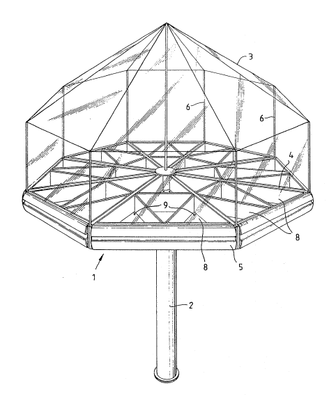
Fig. 1 is a perspective view of the plant growing system
according to the present invention, designed as a table 1,
mounted on a central support 2 and having a roof 3 of a
transparent plastic cloth. The shown embodiment of the table
is polygonal and particularly has a regular octogonal shape.
3~
Table 1 is by means of radial partitions 4, Fig. 3 - called
spoke profiles supra and infra - and a border 5 on all sides
subdivided into sectors 7 substantially having a triangular
shape. The triangles of this embodiment are equally sided
and their central angle is ~5.
~oof 3 is stretched on top of lateral poles 6, which are
placed in each corner of the polygon, i.e. on top of eight
lateral poles 6 according to the shown embodiment. Roof 3
then resembles a circus tent. The roof , which is made of a
transparent plastic cloth, is subdivided into the same num-
ber of sections as the number of sectors 7 of table 1, and
each section covers an adjacent section by a few centimeters.
Each roof section can separately be opened up or all ofthem
simultaneously and be fastened in a single manipulation by
means of a suitable attachment element, e.g. hooks and
crooks, Velcron tape, snap fasteners, magnetic couplings
or tile like, i.e; gadgets which do not have to be described
in detail in this text. Suitably said attachment elements
are designed in such a manner, -that e.g. all plastic sections
can he attached above one single sector 7 of the table and
a maximum accessibility ot all parts of the plant table be
attai~.ed.
Each sector 7 forms a frame for, according to the shown em-
bodirnent, four triangular plant boxes 8,8a. Plant boxes 8,8a
have such a si~e, that four of them will fill the frame in
a sect-or completely. Plant containers 8a, which are disposed
adjacent the center of table 1, preferably have a blunt point.
For the rest containers 8,8a have the same size, and the
three outer plant containers 8 are completely identical.In
each corner containers 8 are in their bottom provided with
a drainage hole 9. Containers 8a are also provided with a
drainage hole 9 in two of their corners and preferably with
two drainage holes 9a in that corner, which faces the center
of the table, Fig. 2.
- , ~ ', , ~ '
.
3~ ~
Fig.~ and 5 show how spoke profiles/partitions 4 are de-
sig1l~d. Spoke prof~les 4 are made of an aluminum profile,
~7hich is stamped all of a piece and comprises a vertical
~eb 12 and at the top a double flange 13 having an even top
surface as well as a screw holder 14 between said flange 13
and web 12. Also, in its lower portion spoke profile 4 on
each one or its sides has a bearing support, generally di-
signated 15. Each bearing support 15 also forms a channel
16, ~hich is defined by an even horizontal bottom 17, a
verticai lateral wall 18 as well as the lower por-tion of
web 12. ~ lower screw holder is designated 19.
In Fig. 6 a cross-section is shown of an embodiment of bor-
der profiles 5, which like spoke profiles 4 in their lower
portion have a bearing support 21, which also forms a chan-
nel 22, which faces the center of the table, bearing support
21 comprising an upright flange, which constitutes one of
the walls of channel 22. Border profile 5, which also comp-
rises an aluminum profile, which has been extruded all of a
piece and has a vertical even web 23, which faces the cen-
ter of the table, as well as outer portions, which include
a lower bent portion -4, an upper even portion 25 and out-
side the latter a bent upper portion 26, which forms a grip-
ping handle to be used when table 1 is to be revolved. A
connecting element, deisgned for an assembly of spoke pro-
files 4 and border profiles 5, is designated 28, Fig. 4.
Each connecting element 28 includes a vertical hole 29 for
the mounting of lateral poles 6 for roof 3.
A hub is generaily designated 30, Figs. 4 and 7. In the
shown embodiment hub 30 comprises an inner sliding sleeve
31 having a folded upper edge 31a and on which an attachment
sleeve 3~ has been mounted, which is retained on sliding
slee-ve 31 by means or a cover 33. Attachment elements 34
a~.e mounted on attachment sleeve 32 and designed for the
mounting of the i.nner ends of spoke profiles 4 by means of
scre~ls 35, wh_ch extend into screw holders 14,19, Fig. 5.
3~
Border profiles 5 are, by means of said connecting elements
28, connected to spoke profi]es 4 at the outer ends of the
latte r, The mounting can also in this case be done by means
of a screw fitting, using screws 37, which extend into screw
llolders 14,19, and screws 38, wllich connect border profiles
5 ~ith legs 39 of connecting elements 28 respectively.
The system works as follows. Plant containers 8,8a having
bottoM holes 9,9a are positioned on bearing supports 15,21
of spoke profiles 4 and border profiles 5, holes 9,9a being
arranged in such a way, that they are placed above channels
16 or 22. Water, which is not absorbed by the soil but flows
t!lrough holes 9,9a, is collected in channels 16,22, channels
22 co~nunicating with channels 16. Also, channels 16 and 22
have SUCll a large volume, that they can accumulate a suffi-
cient amoullt of water, the water, without any overflowing,
being guided along, channels 16 towards the center of table
l. According to one embodiment the water is allowed to drop
or llow towards the central support 2 and pass along its ex-
ternal side downwards into the ground or the like support.
In an alternative embodiment a collecting vessel can be moun-
.ed oll eentral support 2, e.g. in case the system is to be
used indoors.
Fiy. 8 shows an alternative embodiment of the invention. The
table in this case comprises four sectors of the same type
as tlle ones in the embodiment described supra, the table
being r.ounted against e.g. a wall. The central support is
in this case replaced by half a cylinder, provided with
stationary mounting elements of the same type as shown in
Fig. 4.
Fig. 9 shows an additional embodiment, which comprises only
two sectors 7, which are designed for a mounting of the
plant table in a corner.
`
;
9 ~ 3~3
The present invention can of course be modified within the
scope defined hy the following patent claims, and the desc-
ription above is merely one example of a preferred embodi~
ment. Thus, the roof can e.g. be designed in a plurality of
ways. Instead of lateral poles, which support the plastic
roof, e.g. a round or polygonal ring can be used, which by
means of a cross or the like is attached to the center pole,
~hich in its turn is screwed into the cover. In this way a
completely open space below the roof, avallable for work,
can be obtained. Roofs of plexiglass in sections can also
be used.
.
'~ ' ' ,