Note: Descriptions are shown in the official language in which they were submitted.
20~9774
8BLF-COOLING LANCB OR TUYBRB
This invention relates to a self-cooling lance,
tuyere, pipe or other tubular member for the conveying of
gases, liquids or solids into or onto a metallurgical bath
or related melt.
Current technology for the conveying of gases,
liquids or solids into metallurgical vessels utilizes
fluid cooled lances (water cooled in particular),
monolithic and composite lances, and lances employing a
10 mec-h~n; sm that swirls the gases within the lance. Water
cooled lances are complicated in design, consisting of a
plurality of chambers and tubes. They pose a safety
hazard, due to the presence of large circulating flows of
water in close proximity to a high temperature bath,
making them unsuitable for continuous use in an immersed
application. Monolithic lances made of metals, ceramics
or refractory clad metals are known to progressively wear
away from the tip very rapidly or to have the submerged
portion fail. Lances employing a swirling mechanism are
relegated to use in molten slag, with injection into other
types of metallurgical melts being too severe an
2049774
application, resulting in rapid consumption of the lance.
The object of this invention is to provide a
self-cooling lance or tuyere, based on current heat
pipe/thermosiphon technology, which is able to operate as
required in a metallurgical environment. Another object
is to provide a lance so that if there is a failure, there
would be a minimal safety hazard.
The self-cooling lance or tuyere in accordance
with the present invention generally comprises a heat pipe
or thermosiphon made of two tubular members defining a
closed annular region for a working substance, the inner
tube member being the channel by which the feed materials
are conveyed into or onto the metallurgical bath.
Those familiar in the art of heat pipes will
know that a heat pipe or thermosiphon uses a material
known as a working substance that is contained in a
hermetically sealed vacuum. As heat is supplied to the
working substance, it evaporates and its vapour flows to
the cooler end of the heat pipe where it condenses as a
liquid and flows back to the evaporator end of the heat
pipe to repeat the cycle. The choice of working substance
is dependent upon the application. For example, an
application that requires a lance temperature of 850C in
an environment at 1200C would have sodium (boiling point
= 882.9C) as a working substance candidate. Working
substances for lower temperature applications include
2049~74
selenium, potassium, cesium, sulphur, sodium, and mercury.
Working substances for higher temperature applications
include zinc, magnesium, lithium, and silver. After
selection of the working substance, the pipe materials may
be chosen. The amount of working substance used depends
on the lance dimensions but a maximum would be in the
order of a few kilograms. A heat pipe/thermosiphon in a
vertical position, utilizing gravity to return the working
substance to the evaporator, is properly termed a
thermosiphon. If other forces, such as capillary, return
the working substance the correct term is a heat pipe.
Heat is transferred via the latent heats of
evaporation and condensation of the working fluid. The
heat pipe attains a very high effective thermal
conductivity and the result is that the evaporator and
condenser regions achieve a near uniform temperature in
between the heat source and the ambient.
A lance utilizing heat pipe technology would
preferably be made by creating an annular region between
two concentric pipes using a washer shaped piece at each
end of the concentric tubes. The annular region may also
be defined by one or both of the tubular members having a
non-circular geometry. As well, the outer member may be
sectioned, while maintaining a closed annular region, so
that the diameter of the condenser region is greater than
that of the evaporator. The inner pipe may be extended at
2049~74
the gas, liquid or solid entrance to ameliorate coupling
of the gas, liquid or solid sources with the lance. When
the lance is inserted into a furnace, the annular portion
of the lance which is in the furnace acts as an evaporator
and the portion removed from the furnace acts as the
condenser. The lance achieves a temperature in between
the furnace and ambient temperatures. The temperature at
which steady state is achieved is a function of
a) the heat transfer into the lance as per the
application,
b) the physical properties of the working substance,
c) the thermal conductivity of the pipes,
d) the gas flowrate down the inner pipe,
e) the ratio of surface areas between the evaporator and
condenser sections,
f) the heat transfer from the condenser according to the
ambient conditions, and
g) the vacuum in the annular region.
Once the lance is constructed it is possible to
adjust the temperature during operation, without affecting
the process, by the adjustment of parameters e, f and g.
The ratio of the evaporator to condenser areas can be
controlled by insulating a part of the condenser. Heat
transfer from the condenser may be increased by air or
water cooling. The vacuum in the annular region may be
adjusted.
Z049774
Measurements from a pressure transducer of the
vapour pressure of the working substance in the annular
region can give an indication of the vapour temperature
and thus the lance temperature. The lance would be
designed so that the vapour pressure of the working
substance would be less than one atmosphere and thus pose
a minimal risk.
An amount of inert gas, present in the annular
region, will oppose the working substance vapour. Its
pressure may be adjusted via a connection to a gas supply
or a vacuum pump. Its function is to be forced to the
furthest portion of the lance from the evaporator so that
such region does not participate in the evaporation and
condensation of the working substance. Thus this region
remains at a near ambient temperature and thus protects
the said pressure transducer from heat failure.
If a heat pipe lance is used in a non vertical
position capillary forces aid in the fluid return. To
fully utilize capillary forces, a wick material coating
the outer surface of the inner pipe and the inner surface
of the outer pipe, well described in the art of heat
pipes, is required to ensure that the working substance
coats the entire surface area.
Lance failure could occur in the furnace
environment. However, the small quantities of working
substance, its elevated operating temperature, and its
2049774
relatively high boiling point precludes the possibility of
a safety hazard resulting from contact of the working
substance with the molten charge in the furnace.
Furthermore, by designing the lance so that the vapour
pressure in the annular region is less than one
atmosphere, lance failure would result in materials being
drawn into the annular region, rendering the working
substance harmless.
The invention will now be disclosed, by way of
example, with reference to the accompanying drawings in
which:
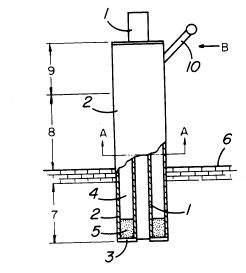
Figure 1 is a diagram of a heat
pipe/thermosiphon lance with a cutaway view showing its
cross section in the vertical plane;
Figure 2 is a view taken along lines A-A of
Figure 1; and
Figure 3 is a view of Figure 1 in the direction
of arrow B.
The lance or tuyere is made of two concentric
pipes 1 and 2 which are closed at each end by a washer
piece 3 defining a closed annular chamber 4 containing a
working fluid 5. The process gases, liquids or solids are
injected into the inner pipe 1, which is extended from the
outer pipe 2, to aid in the coupling of a source of the
process gases, liquids or solids into the inner pipe 1.
The lance is inserted through the furnace roof 6 a certain
7 ;~049774
length 7. The working fluid 5, in the annular region 4,
evaporates in the evaporator region 7 of the heat pipe and
flows to region 8, in the orientation of Figure 1 it
rises. The vapour condenses along the inner wall of the
outer pipe 2 and the outer wall of the inner pipe 1 in the
condenser portion of the lance. The liquid from the
condensation flows back to the evaporator section 7 and
the cycle continues. The inner surface of the outer pipe
and the outer surface of the inner pipe may be coated with
a wick material 11 to aid fluid flow to the evaporator.
Furthest from the evaporator, there may be a portion 9
where inert gas is accumulated and at a temperature lower
than the condenser.
A tube 10 is welded onto the outside of the
outer tube 2, where a hole has been drilled to allow the
charging of the working substance 5. The tube is branched
with both ends attached to valves 12. The valves are
followed by a nipple or fitting for hook-up to a vacuum
pump (not shown) for changing the vacuum in the annular
region, and a pressure transducer 13, to measure the
vapour pressure of the working fluid in the annular region
in the lance. The valves and pressure transducer must be
located above the washer piece 3.
The invention will now be disclosed, by way of
example, with reference to tests performed with the
following heat pipe.
8 2049774
Table 1. Heat Pipe Lance
Length 1.02m
Material 316L Stainless Steel
Inner Pipe 0.3175cm ID, 0.635cm OD
Outer Pipe 2.66cm ID, 3.34cm OD
Working Substance 30g Sodium
Vapour Pressure at 25C 0.0286 atm
A 30.5cm length was inserted into a resistance
furnace at 1200C. The steady state lance temperature was
800C, 400C less than the furnace. The vapour pressure
was 1.30 atm and the condenser length was 37cm. The lance
was tested at other conditions, a few of which are shown
in Table 2.
2049774
g
Table 2. Heat Pipe Lance at Various Conditions
Furnace Inner Pipe Gas Flow Lance Lance Condenser
Temp. Gas Flow Over Vapour Temp. Length
Condenser Pres.
(C) (Lpm) (m/s)(atm) (C) (cm)
1200 0 0 1.30 800 37
1200 50 0 0.96 773 35
1200 0 9.5 0.74 660 29
1250 0 0 1.56 820 43
The tests showed that increasing the heat
transfer from the lance by blowing air through the inner
pipe or by blowing air over the condenser surface
decreased the lance temperature, sodium vapour pressure
and condenser length. Increasing the furnace temperature
increased the lance temperature, sodium vapour pressure,
and condenser length.
Although the invention has been disclosed with
reference to a preferred embodiment, it is to be
understood that various alternatives are also envisaged
within the scope of the following claims.