Note: Descriptions are shown in the official language in which they were submitted.
1164-01
049~77~3
HELICAL HYDRAULIC PUMP
This invention relates to an apparatus for using water wave
motion and particularly to a wave powered pump.
Power generators of various types have been proposed to convert
movement of waves or tides into rotary motion which is used to turn a
generator. For example, a tide operated generator is shown in U.S.
Patent 4,541,242 and a ratchet type wave motor is disclosed in U.S.
Patent 2,009,939. However those devices do not provide a simple
inexpensive safe dependable pump for use in such applications as
pumping bilges of boats left for extended periods of time at moorings.
Known electrical pumps used for this purpose have a tendency to burn
out if allowed to run dry if controls are not provided, or if any provided
controls fail to operate properly. Other problems include failure of
power supply, shorting out of immersed pumps and inability to pump
when a reservoir or sump is very shallow.
The pump of this invention is not limited to pumping bilges
however: many other uses may be found for a slow moving reliable
pump which is self priming, and requires no one way vaIves. A larger
version of the pump of this invention is suitable for such applications
as irrigation. It will be appreciated that a continuous supply of water
.
from a dependable wave powered pump could replace an intermittent
high flow rate gasoline engine pump or a pump driven by an electric
motor. Furthermore, the pump of this invention is not limited to
puinping water, and can be used for any low viscosity liquid.
It is therefore an object of the present invention to provide a
i~ pump capable of being powered by water motion, wave motion or other
slow or intermittent power sources.
:
,~ .
' ~ ~ ` ' '.
. ~
1164-01
2~ g77
-2-
Another object of the present invention i9 the provision of a pump
which will move fluids through a conduit without the use of valves.
Another object is the provision of a pump which i8 capable of
being self priming.
.
A still further object is the provision of a pump which has few
moving parts and is therefore simple and inexpensive to construct, easy
to maintain, and reliable in operation.
Accordingly the present invention provides
A fluid pump adapted to be rotated by wave or water power
through the use of ratchet means, said fluid pump comprising:
- a conduit in the form of a helix support means for said
helix rotationally supporting said helix for rotary motion about its
longitudinal axis, an inlet means at a first end of said helix for scooping
fluid, and an outlet means at a second end of said helix aligned with
said shaft; and
:
The invention further provides
;~ ~ a fluid pump wherein said helix is formed of tubing and
said outlet means comprises a rotary seal between an end of said heli~
and outlet conduit means; and wherein said inlet is an open-ended semi-
::
circular coil of said heli~.
~:
; ~ ~In the accompanying drawings which illustrate preferred
embodiments of this invention:
.~
Figure 1 is a perspective view of a pump in accordance with this
~; invention;
'
- .
` ~
.
.
,
1164-01
~:04L9~7713
-3 -
Figure 2 is a top plan view of the pump of Figure 1 mounted in a
housing;
Figure 3 iB a side elevational view of the pump of Figure 1
immersed in liquid; and
Figure 4 is a part sectional enlarged view of the inlet and outlet
means of the pump.
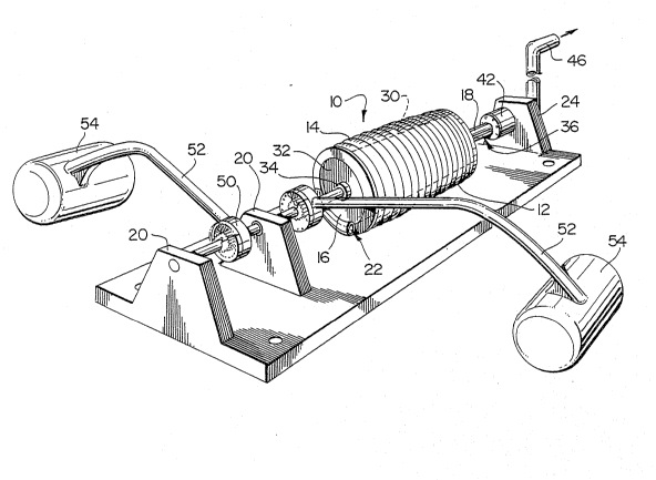
Re~erring now in detail to the drawings, the pump shown
generally at 10 in Figure 1 has a helix 12 constructed of tubing 14 on
support means, or spacers 16 for mounting the helix 12 on a suitable
shaft 18 extending through the longitudinal central axis of the helix 12.
The helix is mounted for rotation on suitable supports 20 as shown in
Figure 1 or in a housing 24 as shown in Figure 2.
In one ~orm this tubing 14 is wrapped on a mandrel 30 indicated
:~ ~ by broken lines in Figure 1. In this embodiment spacers 16 are in the
~: form of end caps 32 (one of which is shown in Figure 1) having central
hubs 34 through which the shaft 18 extends.
~:As shown in Figure 4 at least an end portion 36 of the shaft 18 is
:~ ~hollow so that an outlet end 38 of the helix 14 can be in communication
with the shaft 18 as through a suitable aperture 40 in the sha~t 18. The
end portion 36 of the shaft 18 is received in a conventional rotating
shaft seal 42 having an o-ring or packing bearing on the shaft to provide
substantially fluid-tight connection between the hollow rotating shaft
18 and an outlet conduit 46.
. ~Rotating motion of the pump 10 is provided by at least one ratchet
mechanism S0 secured to the shaft 18. The ratchet means 50 has an
arm 52 and a float 54 at the end of the arm 52. Movement of the arm
.::
~ ~ ' ` `' " '
.,~ ....
.. . .
1164-01
77~3
_d~ _
52 causes rotary motion of the shaft 18, in this case counterclockwise
motion as viewed in Figure 1 and as indicated by the arrows in
Figure 4.
It may not be esserltial to provide a rotating joint between the
tubing and an outlet conduit for some applications particularly where
flexible tubing is used for the outlet or the entire helix. The flexilble
tubing will rotate and can be guided within a conduit or the like, not
shown, similar to conduit 46. For applications such as irrigation the
outlet end would then rotate within the guide and deliver liquid at the
end of the guide.
.
In operation the pump is mounted in an environment where there
i9 relative motion between the arms 52 and the shaft 18. This motion
is transmitted through the ratchet(s) 50, and causes the shaft to rotate.
Liquid will be scooped by the inlet portion 22 of the helix 12. Further
motion, in this case counter clockwise motion as viewed in Figure 4
causes the fluid to move through the tubing helix 14. It will be noted
",
that the pump 10 is partially submerged so that air also enters. As the
helix 12 continues to rotate liquid moves from the inlet end of the helix
to the outlet end and will travel up the conduit 46.
.:
.
In order to maintain the pump 10 in a partially submerged
position the support 20 or housing may be allowed to float while being
tethered, so that relative motion of the ratchet means 50 will turn the
shaft 18 without rocking or raising the support 20 or 24. One such
means for adjustably mounting the pump is retaining screws 56 which
allow vertical movement of the support 20.
Alternatively, the outlet 46 can be slidably located in a suitable
'
1164-01
L977
-5 -
housing, not shown, thus also permitting vertical movement as the
liquid level changes.
Although the embodiment of the pump 10 described above is
particularly suited to wave motion type drive means, it will be
understood that the ratchet means could be adapted to tidal power and
thus the ratchet means would provide the required rotary motion of the
pump as the tide rises and falls. Pumping sea water to evaporation
beds could be carried out in this manner. Furthermore, the pump of
this invention can be driven by electrical means such a solenoid to
provide a slow or measured intermittent supply of a liquid or slurry.
Various changes in the dimensions to accommodate a variety of
applications will occur to those skilled in the art. Such variations are
believed to be within the scope of the present invention. E`or example,
a small bilge pump having a helix formed of 15 turns of 1/4 inch tubing
on a 1-3/4 diameter core will raise water about 18 inches. A larger
model of the pump constructed of 7 turns of 1-1/4 inch tubing coiled to
provide a helix 11 inches in diameter raises water over 5 feet in the
outlet conduit.
., ~
:
:
~ ~ .
." .
,. ~ .
,~; .~ . - . ,
.. ,.,. ~ .
~ , ' ' '
.