Note: Descriptions are shown in the official language in which they were submitted.
A heating device and systems to reduce surface tension and
viscos~ty characteristics of flu;d fuels.
The present invention relates to a heat gathering device and systems,
that allows Direct or Indirect heating of fluid fuels, by proximity
to e~gine exhaust systems. To cause a reduction in the surface
tension and viscosity characterist~cs when used ~n fluid fuel burning
engines. ~hen such a modified fuel ls applied to known and current
carburation and injection systems, a much finer atomisation results.
This allows power generation improvement for less fuel was~age and
10. reduces the obnoxious elements in the exhaust fumes. Thereby,
cossett~ng a non renewable resource - Fossil fuels.
Throughout the development of automobile carburation many forms of
apparatus have been devised to redu~e consumpt~on of fluid fuels.
Each of~them reaching for temperatures produc~ng vapourization of the
fuel.
~hllst most of those devices were successful in producing the objective
~apour; n3ne of the engines produced over these years was capable of
uslng such a vapour. Either inltially or on a continual basis. Because
vapou~ts~tlon caused caused excessive and rapid internal wear; fast
20. breakdown of lubrication oils and their attendant systems; excess~vely
high operatlon temperatures; and d~fficulty in gaining control on
engines fed with fuel vapour.
It is desirable to introduce a process that will allow all current
carburation and ~nject~on systems to accept and use wlthout damage,
a fuel me~um that retains its fluid properties. Allowing the exist~ng
systems to produce a finer atom~sat~on.~Which in turn~g~ves a qu~cker
and more complete combustion of the fuel presented. Resulting ~n more
power produced for less volume of fuel used. Producing exhaust fumes
that bear lower levels o~ obnoxious elements, than the same carburation
system produced before the heating of the fuel. All of ~his can be
achieved by heating the fuel stock ~o a much lower ~emperature than
that for Yapourization.
The present in~ention produces heated fluid fuel feed-stock at the more
desirable lower temperature ranges and always presen~s fuel in a fluid
form, to the atomization stage. Avoiding the very undes~rable
~apourization produced by other devices. The warmed fuel~ hav~ng a
1~. lower surface tension and viscosity, is easily processed into finer
atomization, by ~he original carburetor or injection system, without
modification.
The invention consists of a heat gathering main chamber, which carries
a smaller chamber in parallel with it~ They are coaxial, w1th the
smaller chamber connected to the inlet and outlet of the main chamber.
Both are preferably cyl~ndrical in form, with closed but vented ends.
A flow control orif~ce ~s arranged at the entrance and exit of the
small chamber. Each orif~ce has a parabolic cross section th~t provides
two dlstinct le~els of flow character~stic.
20. A s~m~lar parabolic cross sectioDed orifice of a higher flow capac~ty
ls s~tuated down stream~froc the main chamber. ~ ~
Right acrcse the down~stream end of~the main chamber, a~sealed retent~on
bulkhead is arranged. This carr~es another flow control orlfi~e, in its
upper quadrant.
The parabolic cross sect~on~o~ the con~rol orlf1ces~provides two
separate flow cond~tions. At low flow pressur~s the~parabolic profile
:
causes a turbulant collar to Pcrm in the exlt passage o~ the orifice,
_3_ ~
:
giving it a flow reluctance property. At higher flow demands, the
greater pressure drop over ~he orifice configura~ion, causes the flow-
reluctance collar to wipe out~ Providing an ins~an~ increase in flow,
without introduction of mechanical moving parts.
Each of the orifices will respond immediately on application of an
increased pressure drop, Providing an upper flow condition, sh~uld it
be required, for high power demand or emergency.
The combined effect of ~he flow control orifices and the incre~sed
cross section of the main and small chambers comb~ned is to slow
lO. down the passage of the fuel as it passes through th~s section of
the ciru~t.
Slowing the passage of the fuel down, inside this dev~ce, allows the
fuel time to heat up to the desired levels, for surface tension and
~iscosity reduction.
By carefull arrangemen~ of the d~sposition of the maln chamber; near,
to the full range of heating, can be achieved.
The ref~nement ( more heat, or less, if requ~red ) can be ac~ieYed by
rot~tlng the main chamber such that it carr~es the small cha~ber nearer
to the heat source, or away from it. Thus prov~dlng a refineme~t fac~l~ty
20. for the heat gathering character~st~cs.
This heat gatherlng var~able, can be used to achleve the temperature
range of response requlred a~ the carburetor.
This ~nvent~on intends that the heat gathering vessel has two uses.
One for heat~ng fluid fuels wlth1n itself, for dtrect supply to the
carburator, called "DIRECT". Or~ another use ( 1n the same conff ~uration 1;
gathering heat into a h~gh temperature oil body w~th~n the device, for
_4_
indirect heat supply to the fuel system of an englne, via a contra-flow
heat exchanger~ called "INDIRECT".
The known and proven ~empera~ure ranges ~or the fuel to enter the
carburetor or injection system are :- 83F ~o 124F for summer fuels
and 67F to 104F for winter fuels, for them to gain sufficient surface
tension and viscosity reduction and give subsequent performance
impro~ement across the engine, using gasoline. The range for diesel
fueled eng~nes ls 87F to 137F,
Both the 'DIRECT" and "INDIRECT" systems will provlde the required
lO. heat boos~, Each in ~ts own safe manner.
The DIRECT system works w~in the prescribed ranges and is the
cheaper sys~em to instal.
The INDIRECT system can be se~ to operate on more refined ranges. Is
useful for hard access systems.
To rel~veexcess fuel pressure ~n both systems, caused by continued
heat~ng after eng~ne shut down; a fuel filter w~th a constant bleed-off
back to the fuel tank, ~s provided. Aga~n, thls flow ~s controlled by
a very s~all d~ameter parabol~c orifice ~nserted in ~he bleed~of~ llne,
: ~
There are two systems for the opera~on of the INDIRECT m~thod. A simple
20, convect~on circu~t and a pump assisted circui~
Both Ind~rect systems can carry a flow control valve ln the hot r1ser
line, that is controlled in turn by a thermostat placed ~n the fuel
llne~ just before the carburetor.
: :
Both of these ~nd~rect systems, are toppQd up~a~nd expanslon rel~eved
w~th~n the1r high temperature oi1~ systems,; by prov~s~on of a gravi~y
-5-
'
:
,~
feed tank, situated and connected to the bottom of the 'cold' return
line.
Application of this inven~ion and its systems, is not confined to
automo~ive outlets. The princ~ples can be design adapted to operate
on stationary engines and any process relying on refined atomisation
of fluid fuels for econom~c combustion, w~thin ~ts operation.
The in~ention, as exemplif~ed by prefered embodiments, is described
w~th referance to the drawings in which :-
F~gure I is a schemat~c of the device with ~nternal de~ails and
dep~cted in the "DIRECT-USE CIRCUIT"~
F~gure II is a schematic of the device depicted in the "INDIRECT-USE
CIRCUIT".
Figure III Shows the ro~ational effect on ~he comb~ned heat output
of the small parallel chamber. From the hottest to the
coldest conditions.
F~gure IY Shows the low pressure drop flow cond~t~on~ for the
FLO~ RELUCTANCE ORIFICE.
F~gure V Shows the hlgh pressure drop flow cond~tion, for the
FLOW RELUCTANCE ORIFICE.
F~gure VI Shows the SIGNIFICANT TEMPERATUR~E RANGES for operat~on
of th~s ~n~ention, ~n chart form.
F~gure VII Shows the TEST-DETE2MINED EFFECTIVE TEMPERATURE RANGES for
for surface tens~on and v~scosity reductlon of winter
and su -er gasol~ne fuels. Us~ng results from systems
test mod~f~ed by thls ~nvent~on.
F~gure VIII Is a tabulation of EXHAUST EMI~SSIONS ANALYSIS~with c~mpar~son
across s~x representat~ve modern automob~les with the~r
relevant part~culars.
~-6-
a~
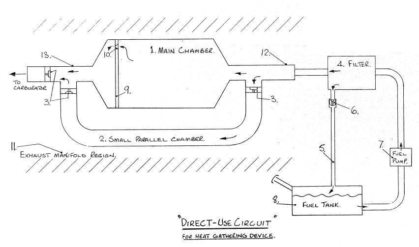
Refering to Fig I, which depicts the principal antkipated embodiment
of this invention, within a DIRECT-USE CIRCUIT; to achieve the reduction
of surface tens~on and viscosity charac~eristics of the liquid fuel
being processed by the apparatus.
The device is a combination of two chambers, used to gath~r heat from
an engine source and ~ransfer that heat to the body of l~quid fuel,
within the apparatus.
The Main Chamber 1 Fig.I. would more often take a cylindrical formation,
made of a good heat conduct~ng mater~al such as copper. Confined
applicat~ons could call for other cross sect~ons for th~s chamber.
Each end being conical to form the reduced cross sec~ion for the ~nle~
and outlet branches 12 & 13 Fig I.
The second chamber 2. Fig,I, is a smaller tubular chamber9 arranged to
run parallel with the main chamber.
Achieved, by permanent Tee junct~on w~th the ~nlet 12 and outlet 13 of
the maln chamber.
Each of these components being made of a sim~lar good heat conduct~ng
mater~al such as copper.
All the component material and the construction brazing ~3 to be of
materlal capable of w~hs~and~ng the hi ghest ~nternal cumbust~uh eng~ne
exhaust manifold tempera~ures, wi~hout melting, dlstort~Qn~or ~eakening
of the device.
The pr~nc1pal object~ve of th~s apparatus is to slow down the passage
of the fuel as it passes the heat gather~ng zone. Th~s ~ch~eved ~n
:
two ways. ;
-7-
:
One by increasing the crossec~ion presented to the flow of the fuel
within the de~ice.
This being the combined cross section of the Main chamber 1~ and the
small parallel chamber 2.
This combined cross section is varied to suit the peak demand flow of
the engine be~ng modified. Along with the combined volume of the
structure to gain the required temperature contro1 of the feed stock
to the carburetor.
To further assist in this temperature control, the small chamber 2, is
used in a very particular manner during commissioning of a modifying
installation.
To fully describe th~s characteristic of this invention, referance is
made to Figure III.
As a refinement facillty to the f~nal heat output of the whole dev~ce;
the small chamber ~s used to provide hea~ increase or r~duction for the
r~ser to the carburetor. This is achieved by rotat~ng the small chamber
clo~er to the exhaust manifold, or further away from that heat source9
as shown ~n ~igure III.
Where pos~tion 1 Fiy III9 is considered the pr~me sett~ng position for
the small chamber, 6iving the most NEUTRAL tempera~ture influence.
An extra heating ~nfluence ~s gained by rotating the~ma~n ohamber, to
cause the small chamber to move from pos~tion'1 ~through '~2' to '3'.
There w~llbe a gradual and dlst~nc~ r~se ~n the temperature of the
comb~ned flow from the main chamber and the small chamber, This Is
because the small chamber is capable of absorb~ng more heat when taken
closer to the heat sourCe, the exhaust manifold.
-8-
~ a~ a~ 3
An extra cooling influence is gained by rotation of the ma;n chamber
taking the small chamber from position '1' through '4' to '5'; which will
cause a drop in the combined fuel output temperature, from the invention;
as the small chamber moves away from ~he heat source and deeper into
the cooling SLIPSTREAM, passing the engine. BothJ when the vehicle is
in motion and under the radiator fan's influence. There is an additional
cooling effect, caused by the small chamber being screened from the heat
source, by the main chamber.
Should the device be clamped direc~ly to the manifold; then the modulating
effect of the `small cham~er posi~on, w~ll have an even stronger influence
and control value, on the combined outle~ condition.
The small parallel chamber has another subsidary function. It is also
a complete alternative supply to the main chamber. Should ~he main chamber
orif~ce beco~e choked.
Thus providing a safety cover, by g~ving a cont~nual supply capable of
susta~ning full operation of the eng~ne. No matter what final position
or attitude is adopted for thermal control.
The SECOND and addit~onal method for gaining a slowing down of the fuel
flow through the invent~on, is brought about by appl~cat~on of four
FLOW RELUCTANCE ORIFICES, d~spersed about the de~ice in the strategic
positions shown at points 3 and 10 Fig.l.
The orifice shown at 10 Fig.I. ~s constructed in the upper segment of
a bulkhead wh~ch completely blocks the wain chamber at the down stream
end, as shown at 9 F~g.I. This or~fice with~n the bulkhead, is to
provide a con~rol that will waintain a very slow flow through the main
chamber. Allow~ng the des~red heat transfer, extra t~me to occur;
_9_
Referance is now made to Figures IV and V., to describe the dual flow
function provided by the FLOW RELUCTANCE ORIFICES, used throughout
this invention and systems.
The ob~ective use of Flow Reluctan~ Oriflces within ~his invention and
systems, is, to achieve two distinct conditions of flow; without use
of mechanical moving parts. Gaining flow reduction conditions during
normal engine operations; that cause slower passage of fluid fuels
through the heating device. Wh~ch will allow eleva~ed heat transfer~
by extending the per~od of exposure to the heat source. Whilst satlsfying
all higher var~ations in flo~ demand, from peak eng~ne operatlon levels.
There are two dist~nct conditions of flow ~hrough Flow Reluctance Oriflces:-
THE SLOWEST, when there is ~he lowest pressure drop across the orifice,
with flow patter~ as shown in Figure IV, and -
THE FASTEST, when there is the h~ghest pressure drop across the orifice,
w~th flow patterns as shown in Figure V.
Cons~der~ng the ~OW PRESSURE DROP CONDITION; ~f a nor~ally right angle
faced or~f~ce mouth, 12 F~g.IV, ls depressed ~nto the body of an orif~ce,
7 Flg.IV; carry~ng a parabol~c~ el~p~ical or spherical profile; the flow
pattern through the remodelled or~fice ~s deformed ~n a defin~te manner,
As shown at 8 F~g.IV.
The flow wh~ch ~s turned down the new proflle f~ce,~collects sufflcient
strength, such that ~t reduces~or WAIST5 the ava~lable flsw diameter
from "D" to an effect~ve 'd'; ~y developing a none flow TURBULANCE
COLLAR, shown at 9 Fig. IV, at the entrance of the or1fioe~
Th~s TURBULANCE COLLAR. ef~ect~vely reduces th~ ava~lable flow, dur~ng
low pressure drop condit~ons across the orif~ce. It ls a very femir or
delicate cond~t~on.~Sustained only at~low pressure ~drop conditions.
Th~s del~cate reduced flow cond~on, is designated as a
FLOW RELUCTANCE FACTOR (F.R.~
-10- :
~ q~
This Flow Reluctance Factor ;s design-sized, to be directly applied
throughou~ the operational conditions of the heat gathering device.
Achie~ing an even slower ~uel flow ~hrough the apparatus. With the
Flow Reluctance Factor matched to the normal/2500 rpm/ highway speed
of a particular engine application.
Considering the HIGH PRESSURE DROP CONDITION; when a high pressure drop
change is applied to the previous delicate cond~tions; there is radical
deformat~on of the established 'turbulance collar', a~ the ~ntrance to
the or~f~ce. As shown in Figure V.
1~ The redirectional capacity of the curved praf~le ~s now LOCKED OFF by
the thrust of the central flow pattern, 10 Fig,Y.
Th~s progress~vely destroys the turbulance collar, as the pressure drop
increases. Reducing it to zero, when sufficient pressure drop ~s applied.
As shown at 11 F~g.Y.
The flu~d body exper~ences a w~dening of the orif~c~ entrance, G~ving
a much ~ncreased flow through the orlf~ce. More closely equal to the
fullest flow capac~ty represented by d~ameter 'D' at 13 F~g.Y.
In thls appl~cat~on of Flow Reluctance Factor to the fuel heater of
th~s ~n~ent~on; the changes in flow pattern des~r~bed above~ are matched
to the cycle of e~ents requ~red ~n the heater, by the varying~demands
from the eng~ne operation. Wlth the s~ze of or~fice and entrance prof~le
chosen carefully; the FLOW RELUCTANCE FACTOR (F.R.F.) ~s used ~o advantage.
By allowing the comb~ned characteristics of the low pressure cond~tion
to match a NORMAL range of operat~on 9 ~ 0~ say, a~ automoblle en~ine. Th~t
~s the zero to 2500 rpm supply range.; The flow reluctance condit~on at
the lower pressure drop status, can be used to enhance the operation
of the fu~l heater. By sat~sfy~ng one of ~ts~ma~n object~ves; which is
to slow down the passage of the fuel, so that i~t will ~etter absorb the
heat ava~lable. as it~passes through the apparatus.
Should a sudden high demand come onto the fuel system, requiring
2500 rpm to 5000 rpm, for a brief period. The higher pressure drop
experienced across all four F.R.F. or~fices in the hea~er; will allow
a much higher immediate flow of fuel demand to be satisfied. Because
all four or;fices will have their TURBU~ANCE COLLARS destroyed and
a fuller flow will result.
The larger ma~n chamber, a~ting as a reservoir of fuel, w~ll also be
able to provide the h~gher flow demand, at the elevated tempera~ures
necessary for continued reduction of ~urface tension and v~ssos~ty.
Whilst the small parallel chamber w~ end to slightly cool the comb~ned
output s~atus of the apparatus. This will ~n no-way de~ract from the
o~erall mechanical response and performance of the englne; in its
endea~our to mee~ the h~gher demand cond~t~on.
By ~nsert~ng orif~ces of ~h~s F.R.F. form, use of mechanical moving
part valves, ~s avo~ded throughout the apparatus. Ga~n~ng an unl~m~ted
operational life; as ~here are no mov~ng par~s to wear or break down.
Inftnltely replaceable fluid formations and c~nf~gurations, provide the
flo~ condlt~on changes requ~red. Thus achie~ng an ~ndef~ite operat~onal
l~fe for the heater. Mak~ng the apparatus a NATURA~ RESPONSE DEVICE.
The flow of fuel through this ~nvent~on w~11 always be d~ctated by the
demand from the eng~ne controls.
::
Each of the or~fices d~spersed through th~s dev~ce are des~gn related
to match the two ranges of flow requ~red by the eng~ne. Sat~sfying speeds
up to normal h~ghway use of 2500 rpo;~also~peak emergency demands for
accellerat~on up to 6000 rpm. ~ ~
The rel~able performance response of~these~or~flces ha5 been proven over
a f~e year cont~nual test~per~od ln modern veh~cles.
-12- ~
~ 3~3~3~3
The variation in volume of heated fuel required has also been proven
as continually effective and adequately supplied by the combined volumes
of the main and small chambers.
Taking observation over several thousand miles of continuous five year
operat70n, has clearly determined the most economic temperature ranges
of operation for this inven~ion to achieve the enhanced performan~e
and emissions reductions envisaged; and to be optimised against safe
engine and automobile operation. Prov~ng no damage to one closely
monitored vehicle's engine over 12~,277 miles of daily observat~on
~n a five year period. A similar record of improvement, covers a ~urther
range of documented vehicles, for this same per~od.
These defined operational temperature ranges are shown in Figure YI.
Now refering to Fig.YI; two distinct temperature ranges have emerged
for gasoline consumption. These are dictated by ~he difference between
the blends of fuels prov~ded in summer to ~hat suppl~ed i~ wi~ter~ Th~se
~enow built into the successful and contlnued operation of this invention,
The overall temperature range for summer fuels9 operating from h~ghway
to city cond~tions is 83F to 124F shown at 2 F~g.VI. With a h~ghway
sub-di~s~on of 90F to 105F shown at 7 Fig.Vi. and city operation of
110F to 124F shown at 8 F~g.VI, The carburetor inlet tempera~ure is
set to operate in the range 90F to 110F to hold the over~ll operation
range, sho~nat 6 Fig.VI.
The overall temperature range for winter fuels operati~g from highway
to city cond~tions is 67F to 104F shown at 4 F~g.~VI. W~th a h~hway
sub-division of 70F to 85F shown at 10 Fig.VI; and c~ty operat~on of
90F to 104F shown at 11 F~g.VI. The carburetor inlet temperature is
set to operate in the range 700F to 90F to hold the overall operation
range, shown at 9 F~g.VI.
-13-
The class of temperatures for SUMMER gasoline is shown at l.Fig VI.
The class of temperatures ~or WINTER gasoline is shown at 3.Flg.VI.
The operation range for diesel fueled engines is 87F to 137F as shown
at 5 Fig. VI.
The progressive effect of this invent~on's ability to reduce droplet size9
within a conventional carburetor is shown in tabular-graph~c form in
Figure VII. The extensive test vehicle results~ over all seasons for
fiYe years, ha~e been used to coalate the effective ranyes f~r both summer
and w~nter gasolines, and are displayed in Figure VII.
Notations are g~ven in each of the f~ve columns representing droplet
reduction, Fig.VII, on ~he status of observed improvement. The ~h~rd column
entitled "PEAK MILEAGE AND HIGHEST EMISSIONS REDUCTIONS" represents the
currently observed performance of this ~nvent~on used as a "DIRECT SYSTEM".
The column entitled "ADDITIONA~ REFINED CONTRO~ RANGE" 1s emerg~ng as
PRACTICAL by use of the invention as an "INDIRECT SYSTEM" f~r heat gather~ng~
The embod~ment of th~s ~nvention shown in Figure I~ is classlf~ed as
'DIRECT-USE'. Figure I, shows the device in a process circu~t where lt is
placed w~th~n close proxim~ty to the engine exhaust manifold, or secured
to ~t; and has the flu~d fuel passing dlrectly through it.
Supply of fuel ~s from the veh~cle's fuel tank v1a its fu~l pump~
'
The c~rcu~t ~s des~gned to pass the fuel thr~ugh a by-pass f~lter, then
~nto the devlce.
The bypass f~lter ~s modif~ed a~ ~ts bypass outlet w~th another Flow Reluctance
Or~fice shown at 6 F1g.1.
::
Th~s orif~ce, by compar1son with~the;other F.R~F. or~f~ces used ~n the
dev~ce; is a very small or ref~ned vers~on. ~;
~: :
~-14-
This is provided to cause a continuous bleed-off from that point in the
fuel circuit, back to the fuel supply ~ank.
This facility also preYents ~ny build up of pressure tha~ will occur after
the engine is shut down. When the residual heat in the exhaust manifold
continues to heat the body of fuel locked in the device.
This also allows natural convect~on of the heat retained in the chambers,
to keep the riser to the carburetor warm for prolonged stationary periods~
w~thout ho~ding the circuit at elevated pressures.
A further embod~ment of the invention is shown ~n F~gure II. Th~s dep~cts
the "IN-DIRECT USE" circu~t for applying the device to an e~gine where it
is undes~rable to carry the fuel close to the exhaust system, for either
thermal or physical reasons. Or where ref~ned controls are prefered.
The construcyion of the ~nvention rema~ns the same. Other than the flow
reluctance orif~ces would be opened up to allow greater flow.
The dev~ce would be mounted on or near the exhaust man~fold as shown
at 3 F~g,II,
The heat transfer med~um would be a body of HIGH TEMPERATURE RESISTANT OILo
The hot o~l from the unit at 1.F~g.II, would be transfered t3 a CONTRA FLOW
HEAT EXCHANGER 2 Fig.II Wh~ch would cause the hot ~1 to flow around a
HEAT TRANSFER VESSE~ 15 Fig.~ll, housed inside the heat exchang~r 2 Fig.II,
be~ng part of the fuel system. The exchanger ~s manufactured from a yood
heat conduct~ng mater~al such a~ copper.
:
Be~ng ~n contra;flow to the fuel~d~rect~on the hot oil will ~part ~ts heat
to the fuel. Such that the hottest oil, entering from the top, wlll come ln
contact w~th the exi~ng fuel.
: -15-
The coolest hot oil will leave the exchanger at the bottom~ where the
fuel enters.
The cold used oil will recircula~e down to the device, for reheating
and upward recirculation.
The colder return line is provided with a gravlty feed expansion and
replenishment tank at 7 Fig.II. Which copes with the fluctuating volume
of the working oil body.
The entire system is insulated against ambient influences, Other than
the necessarily exposed device.
The INDIRECT USE of the device, can be ins~alled wl~h e~ther of ~wo
distinct flow systems~
One where the clrculation is caused entirely by convection. Which would
be acceptable where there ls an abundance of heat and a high fuel flowO
The other, where co~vection can not be util~zed; would be to use a hot
oil pump as a flow ~nducer, shown a~ 6 Fig.II~
Such a pump could be under control from a thermostat 4 F~g.II. Sltuated
in the fuel llne, just before the carburetorO ~hich would ~llow the fuel
system to draw just suff~clent thermal ~nput to ~mprove the status of
atomlzation required at the carburetor 12 Fig.II.
80th of ~hese systems wlll respond to a flow control~valve, 5 F~g,II,
inserted in the hot oil riser just before the Gontra~low heat exchanger,
2.F~g II.
This control val Ye woul d also be con~rolled by the thermosta~ 4 F~g II.
further ref~ning the control of thermal ~nput to the fuel system.
-16-
~ 3~3~
Wi~h referance to Figure II, ~he fuel system is pressure relieved with
a flow reluctance orifice a~ 11, set ;n the bypass system of a protective
filter 10,
This constant bleed-off, is re~urned ~o the fuel supply tank 80 Being
recycled for use again by the ~uel pump 9.
Hea~ source to this indirect system is from the exhaust 14, of the eng~ne
13, being ga~hered for heating the fuel by the device 1, in ~he exhaust
manifold region 3.
The high temperature oil system is purged of any entrapped air at its
h~ghest po~nt, by an air bleed valve 170 This is sltuated just before
the hot oil entry ~nto the contra flow exchanger 2.
The same fuel ~empera~ure ranges for surface tension and viscosity
redu~tion, descrlbed for the 'DIRECT' system, apply to this 'INDIRECT'
appl~cat~on. Giving the same improved atom~sat~on, enhanced power output
and reduced obnox~ous elements in the exhaust fumes.
Us~ng the 'DIRECT' appl~cat~on over flve years, has g~ven results of
~mproved mlleage ranglng between 30% and 85~; th~s range was exper~enced
over extended tests in modern vehicles and is prov~ng consistent for
each class of veh~cle tested.
Nydro carbon levels In exhaust fumes hive dropped from 950 ppm to
20 ppm at 2000 rpm, w~th the use of the DireGt s~s~em. Wh11e carbon -
monox~de has dropped from 7.8g down to 0.12~ at 2000 rpm. Attendent
m~leage ~mprovement for th~s veh~cle was 16.34 mpg to 32.59 mpg on
a h~ghway test. The veh~cle was in 1985 Ford Marquee sta~on wagon
u~th a 5.8 litre eng~nè. W~th th~s effect be~ng cons~stent over a
range of d~fferent test vehicles carry~ng thls lnvent~cn's mod~f~cat~on.
~17-
The exhaust fume reductions brought about by this inven~ion, are well
within the U,S.of A. environmental acceptance levels for automobiles,
of hydrocarbons at 400 ppm and carbon monoxide at 1.5%
The USA levels are taken down s~ream from the catalytic converter. The
levels given for this invention were drawn off before the catalytic
converter on each test vehicle.
The exhaust fumes were analysed on a 'MARQUETTE 42 - 076~- FUEL ECONOMY
INFRA RED GAS ANALYSER, used currently for tuntng high performance and
racing eng~nes. Te5~swere carried out by certif~ed, impart~al and
independant personnel.
~ubr~cating oil ac~dity levels were noted ~o have dropped by 30~, by
the same personnel
~ith th~s invention ~nstalled the use of catalytic conYerters is obviated~
Further examples of emlssions analysis, over other veh1cles carry~ng
th~s ~nvention's modification to the fuel sys~em, are g~ven in the
table shown on F~gure YIII.
Although only two embodiments of the present invent~on have been
descr~bed and ~llustrated, the present ~nvent~on ls not limited to
the features of those embod~ments, but ~ncludes all var~at~ons and
~0 modifications with~n the scope of the claims.
-18-