Note: Descriptions are shown in the official language in which they were submitted.
CA 02050121 1998-09-17
(3)
BACKGROUND OF THE INVENTION
The present invention is generally directed to an automated analyzer for
conducting binding assays of various liquids, in particular biological fluids
for
substances contained therein.
The present invention is particularly directed to a machine for performing
automated immunoassay testing, in particular heterogeneous immunoassays in
which
paramagnetic particles are the solid phase reagent and the labeled reagent
(tracer
reagent) includes a chemiluminescent label. The system can accommodate both
competitive and sandwich-type assay configurations. A chemiluminescent flash
is
initiated and its intensity measured as an indication of the presence or
absence of an
analyte in the test fluid which is being assayed. The analyzer can be
selectively run
in batch-mode or random access sequence.
Over the last several years, automated instrumentation has been developed for
routine testing in the clinical laboratory. Limited automation has been
applied to the
area of immunoassay testing. Although some instruments have been developed for
limited immunoassay testing, many of the procedures are still performed
manually.
Test results are very often delayed because of the time factor and labor
intensity for
many of the manual steps, and long incubation or reaction times. These delays
can
be critical in many clinical situations. In addition, the manual procedures
cause
variations in test results and are quite costly. The causes of such variations
include
nonuniform testing protocols, technician experience skills and the precision
of the
apparatus/analyzer. These and other difficulties experienced with the prior
art
analyzer and manual testing systems have been obviated by the present
invention.
It is, therefore, an object of an aspect of the invention to provide an
automated
analyzer for diagnostic immunoassay testing which is particularly applicable
to
CA 02050121 2002-05-10
(4)
heterogeneous immunoassay testing.
An object of an aspect of this invention is the provision of an analyzer which
has a high degree of versatility, capable of performing a wide range of
binding assay
protocols for a wide range of clinical and non-clinical analytes.
An object of an aspect of the present invention is the provision of an
automatic
analyzer which is capable of handling a plurality of test protocols
simultaneously,
continuously and sequentially.
An object of an aspect of the present invention is to provide an automated
analyzer which is capable of high sample throughput.
An object of an aspect of the invention is the provision of an automated
analyzer which greatly reduces the amount of time per assay or sample test.
An object of an aspect of the invention is to provide an automated analyzer
which provides consistent and reliable assay readings.
An object of an aspect of the invention is to provide an automated analyzer
which is self-contained and requires a minimal amount of space for complete
sample
processing.
An object of an aspect of the invention is to provide a constant luminescent
light source for automatic monitoring of the luminometer calibration of an
assay
apparatus.
An object of an aspect of the invention is to provide an automated analyzer
which can be selectively run in a batch-mode or random access sequence.
With these and other objects in view, as will be apparent to those skilled in
the
art, the invention resides in the combination of parts set forth in the
specification and
covered by the claims appended hereto.
CA 02050121 1998-09-17
SUMMARY OF THE INVENTION
In general, the automated analyzer of the present invention is a self
contained
instrument which is adapted to be located on a suitable laboratory bench. It
requires
no external connections other than a standard power line and operates
accurately
within an ambient temperature range of 18° to 30°C. The
functional units of the
analyzer include a process track, a sample handling or transport system, a
reagent
handling or transport system, a separation and washing system, a detection
system
(luminometer) and data collection/processing system. The reagents and test
samples
are reacted in discreet, disposable cuvettes. The cuvettes are automatically
and
sequentially dispensed from a cuvette loader onto a linear process tract which
moves
each cuvette one cuvette space every twenty seconds. The temperature of the
test
reaction is controlled by a thermal system which preheats the cuvettes and
reagents and
maintains an environmental temperature of 37°C., plus or minus one
degree,
throughout incubation. Test samples are dispensed into the cuvettes by an
aspirating
and dispensing probe and reagents are added at software-controlled intervals
by means
of three aspirating and dispensing reagent probes. The analyzer is
particularly adapted
for performing heterogeneous specific binding assays. The analyzer can be
selectively
run in batch-mode or random access sequence.
Other aspects of this invention are as follows:
An automated analyzer to assay a test sample for any of a plurality of
analytes,
said analyzer comprising:
(a) means for introducing into a cuvette a volume of test sample to be assayed
for a specific analyte,
(b) means for selectively introducing into said cuvette at least one pair of
reagents which correspond to the analyte to be detected such that a test
reaction is initiated between said analyte and said reagents to form a
detectable product,
(c) means for detecting the product of said test reaction, and
(d) control means including central processing means for coordinating the
introducing means for said test sample, introducing means for said reagents
and detection means.
An automated analyzer to assay a test sample for any of a plurality of
analytes,
said analyzer comprising:
(a) an event conveyor for conveying a plurality of cuvettes serially along an
event path from a starting point to a finishing point, said event path
CA 02050121 1998-09-17
5a
including from said starting point: a sample dispense point, at least one
reagent dispense point, and a product isolation point, each of said cuvettes
having a bottom wall, a side wall and a top opening,
(b) a plurality of sample containers, each of said sample containers
containing a
volume of liquid sample to be tested for at least one analyte,
(c) sample aspirating and dispensing means for selectively introducing a
volume of sample from any one of said sample containers into successive
cuvettes at said sample dispense point,
(d) a plurality of pairs of reagent containers, one pair of reagent containers
for
each type of assay to be conducted, each of said pairs of reagent containers
comprising a first container for holding a first reagent and a second
container for holding a second reagent, the first and second reagents for
each of said pairs having a distinct binding substance which corresponds to
the analyte of a test sample,
(e) reagent aspirating and dispensing means for selectively introducing into
each succeeding cuvette at said reagent dispense point a volume of first and
second reagent from a pair of reagent containers which correspond with the
analyte to be detected in the sample, in the cuvette, so that a test reaction
is
initiated between the sample solution and the corresponding reagents to
form a detectable product,
(f) means for isolating the detectable product in each cuvette at said product
isolation point,
(g) means for detecting the product of said test reaction, and
(h) control means for coordinating said event conveyor, said sample aspirating
and dispensing means, said reagent aspirating and dispensing means, said
isolating means and said detection means.
An automated analyzer to assay a test sample for any of a plurality of
analytes,
said analyzer comprising:
(a) an event conveyor for conveying a plurality of cuvettes serially along an
event path from a starting point to a finishing point, said event path
including from said starting point: a sample dispense point, a reagent
dispense point, and a product isolation point, each of said cuvettes having a
bottom wall, a side wall and a top opening,
(b) a sample holder which is located adjacent said sample dispense point and
which supports a plurality of sample containers, each of said sample
containers containing a liquid test sample to be tested for at least one
CA 02050121 1998-09-17
5b
analyte, each of said sample containers being accessible from the top by an
aspirating and dispensing probe,
(c) sample selecting means which includes an aspirating and dispensing probe
for selectively aspirating a volume of sample from one of said sample
containers and for dispensing said aspirated sample into a cuvette which is
positioned at said sample dispensing point and for aspirating a volume of
sample solution from each of said sample containers in a predetermined
selection sequence and dispensing each of said sample solutions into
successive cuvettes at said sample dispense point,
(d) a reagent holder which is located adjacent said reagent dispense point and
which supports a plurality of pairs of reagent containers containing reagent
solutions for each type of assay to be conducted, each of said pairs of
reagent containers comprising a first container for holding a first reagent
and a second container for holding a second reagent, each of said first and
second reagents having a distinct binding substance which corresponds to a
sample analyte to be detected in a corresponding sample solution for
forming a detectable product, each of said reagent containers being
accessible from the top by an aspirating and dispensing probe,
(e) reagent selecting means which includes an aspirating and dispensing probe
for selectively aspirating a predetermined volume of reagent from a pair of
said reagent containers which corresponds with the assay to be conducted
on said sample and for dispensing said aspirated reagent into the cuvette
which contains said sample at said reagent dispense point to form a
product,
(f) means for isolating the detectable product from each of said cuvettes at
said
reagent separation point,
(g) means for initiating a detection reaction in each cuvette with the product
at
said finishing point,
(h) means for detecting said detection reaction in each cuvette, and
(i) control means for coordinating said event conveyor said sample selecting
means, said reagent selecting means, said product isolation means, said
initiation means, and said detection means.
An automated analyzer to assay a test sample for any of a plurality of
analytes,
said analyzer comprising:
(a) an event conveyor for conveying a plurality of cuvettes serially along an
event path from a starting point to a finishing point, said event path
CA 02050121 1998-09-17
SC
including from said starting point: a sample dispense point, a reagent
dispense point, and a product isolation point,
(b) means for introducing a sample solution to be analyzed for a specific
analyte into a cuvette at said sample dispense point,
(c) means for introducing at least two reagents which correspond to the
analyte
to be detected into a cuvette which contains a sample solution at said
reagent dispense point such that a test reaction is initiated between the
sample solution and said reagents to form a detectable product,
(d) a hopper for holding a plurality of cuvettes, said hopper being located
above and behind the starting point of said event path,
(e) a first cuvette feed and orientation mechanism for feeding cuvettes
forwardly and downwardly from said hopper to said starting point,
(f) instrumentation for detecting the product of said test reaction, said
instrumentation being located above and behind said finishing point,
(g) a second cuvette feed and orientation mechanism for feeding cuvettes
upwardly and rearwardly from said finishing point to said instrumentation,
and
(h) control means for coordinating said event conveyor, said sample
introducing means, said reagent introducing means, said first cuvette feed
mechanism, said detection instrumentation, and said second cuvette feed
mechanism.
A cuvette for use in an assay analysis comprising:
(a) four vertical side walls,
(b) a bottom wall,
(c) a top opening, and
(d) a pair of oppositely extending flanges which extend laterally from two
opposite side walls, for enabling said cuvette to be conveyed horizontally
by at least one toothed conveyor.
A reagent container for use in an automated assay analysis comprising:
(a) a bottom wall,
(b) a vertical side wall which defines an inner chamber,
(c) a top opening, and
(d) at least one fin which is located in said chamber for agitating fluid
within
said chamber upon rotation of said container about a vertical axis.
A reagent container for use in an automated assay analysis comprising:
(a) a bottom wall,
CA 02050121 1998-09-17
5d
(b) a vertical side wall which defines an inner chamber,
(c) a top opening, and
(d) an outer skirt which surrounds said side wall, said skirt being attached
to
said side wall near the top of said side wall and extends downwardly
substantially spaced from and parallel with said side and terminating in a
free bottom edge.
A cover for a reagent container said cover being made of an elastomeric
material and comprising:
(a) a continuous side wall for enabling the cover to be applied to the mouth
of
a corresponding container in a sealing fit, and
(b) a top wall which has at least one slit which maintains the sealing
integrity of
the cover while allowing access into the interior of the container by an
aspirating and dispensing probe.
An automated analyzer system to assay a test sample, said analyzer having a
feed and orientation mechanism for a cuvette which is generally rectangular in
cross-
section and which has four side walls, a bottom wall, a top opening and a pair
of
oppositely extending flanges which extend laterally from two opposite walls of
said
side walls adjacent said top opening, said feed and orientation mechanism
comprising:
(a) a hopper for containing a plurality of cuvettes in a random orientation
with
respect to each other and to the hopper, said hopper having a top opening,
a bottom wall side walls and an opening in the bottom wall,
(b) a feeder conveyor which has a section which travels upwardly through the
opening in the bottom wall to a first point at the top opening,
(c) a plurality of spaced projections on one flat side of said conveyor, each
of
said projections being adapted for supporting a cuvette on one of its side
walls to a first point at the top opening of said hopper,
(d) an orientation chute which extends downwardly at an angle from said first
point to a second point, said orientation chute having a pair of upper
parallel slide surfaces which are separated by a slot which has a longitudinal
sliding axis for receiving said cuvette from said conveyor belt at said first
point so that said flanges are parallel with the longitudinal axis of the slot
and are supported on said side surfaces and said cuvette extends
downwardly in said slot to enable said cuvette to slide downwardly on said
chute along said axis from said first point to said second point,
(e) an orientation tube which extends vertically downwardly from said second
point to a third point, said tube having a bottom opening, a top opening for
CA 02050121 1998-09-17
5e
receiving a cuvette from said orientation chute so that said cuvette falls
through said tube to said third point,
(f) an event conveyor for conveying said cuvettes from said third point for
subsequent use of said cuvettes by said analyzer, and
(g) control means for coordinating the feeder conveyor and the event
conveyor.
A feed and orientation mechanism for a cuvette which is generally rectangular
in cross-section and which has four side walls, a bottom wall, a top opening,
and a pair
of oppositely extending flanges which extend laterally from two opposite walls
of said
side walls adjacent said top opening, said feed and orientation mechanism
comprising:
(a) a hopper for containing a plurality of cuvettes in a random orientation
with
respect to each other and to the hopper,
(b) a feeder conveyor for conveying cuvettes in a substantially prone
orientation from said hopper to a first point at the top of said hopper,
(c) an orientation chute which extends at a downward angle from said first
point to a second point for guiding cuvettes in a sliding free fall along a
sliding axis from said first point to said second point, said cuvettes being
suspended by their flanges along said chute so that said cuvettes are
substantially upright as they travel from said first point to said second
point,
(d) an orientation tube for guiding said cuvettes in an upright orientation in
a
free fall from said second point to a third point,
(e) an event conveyor for conveying said cuvettes from said third point for
subsequent use of said cuvettes, and
(fJ control means for coordinating the feeder conveyor and the event
conveyor.
In an automated analyzer in which a test sample to be assayed is contained in
a
cuvette at a vertical reagent dispense axis, aspirating means are provided for
aspirating
a volume of liquid reagent from a reagent container at a vertical reagent
aspirating
axis, moving to said reagent dispense axis and depositing said volume of
reagent into
said cuvette, reagent transport and selection means comprising:
(a) a fixed supporting base,
(b) a reagent tray which is mounted on said base for rotation about a primary
vertical axis of rotation, said tray supporting a plurality of reagent
containers which are arranged in a circle which is concentric with said axis
and which are vertically aligned with said second point, each of said
containers being mounted on said tray for rotation relative to said tray
CA 02050121 1998-09-17
5f
about one of a plurality of secondary vertical axes of rotation along said
circle,
(c) first drive means including a first electric motor for rotating said tray
about
said primary vertical axis of rotation,
(d) second drive means including a second electric motor for rotating each of
said containers about its respective secondary axis of rotation for agitating
the reagent in said containers, and
(e) electrical control means for controlling the operation of said electric
motor
for selectively positioning any one of said reagent containers to said reagent
aspirating axis.
In an automated analyzer to assay a test sample in which a test sample is
contained in a cuvette at a vertical reagent dispense axis, means for adding a
volume of
liquid reagent to said cuvette at said reagent dispense axis comprising:
(a) a fixed supporting base,
(b) a reagent tray which is mounted on said base for rotation about a vertical
axis of rotation,
(c) a plurality of first reagent containers which are arranged along a first
circle
which is concentric with said vertical axis of rotation for containing a first
category of liquid reagent,
(d) a plurality of second reagent containers which are arranged along a second
circle which is concentric with said vertical axis of rotation for containing
a
second category of liquid reagent,
(e) a vertical reagent aspirating and dispensing probe which has a lower free
end,
(f) electrically actuated pressure control means operatively connected to said
probe for enabling fluid to be aspirated into said probe and for fluid to be
dispensed from said probe,
(g) mounting and positioning means for selectively moving said probe into
vertical alignment with said reagent dispense axis, a first reagent aspirating
axis at said first circle and a second reagent aspirating axis at said second
circle,
(h) first electrical drive means for rotating said tray about said vertical
axis,
(i) second electrical drive means for raising and lowering said probe, and
(j) electrical control means operatively connected to said first and second
electrical drive means and to said pressure control means for selectively
positioning said first reagent containers to said first reagent aspirating
axis
CA 02050121 1998-09-17
Sg
and said second reagent containers to said second reagent aspirating axis
for selectively positioning said probe above a reagent container at either of
said first and second reagent aspirating axes, for selectively lowering said
probe into a selectively positioned reagent container at either of said first
and second reagent aspirating axes for aspirating a predetermined volume
of reagent solution from said selectively positioned reagent container,
raising said probe, positioning said probe above said cuvette at said reagent
dispense axis, and lowering said probe into cuvette and dispensing said
volume of reagent into said cuvette.
In an automated analyzer in which an empty cuvette is located at a vertical
dispense axis, aspirating and dispensing means are provided for aspirating a
volume of
sample to be analyzed from a container at a vertical aspirating axis, moving
to said
dispense axis and dispensing said volume of sample into said cuvette at said
dispense
axis, and conveyor means are provided for conveying said cuvette from said
dispense
axis for subsequent use by said analyzer, a sample transport and selection
system
comprising:
(a) a fixed supporting base,
(b) a tray which is mounted on said base for rotation about a vertical axis of
rotation,
(c) a plurality of sample containers which are supported on said tray in a
circle
which is concentric with said axis of rotation and which intersects said
aspirating axis, each of said containers containing a specific sample for
analysis,
(d) drive means including an electric motor for rotating said tray about said
axis of rotation, and
(e) electrical control means for controlling the operation of said electric
motor
for selectively positioning any one of said sample containers to said
aspirating axis for aspiration of the sample in the container by said
aspirating means.
In an automated analyzer in which a cuvette is located at a vertical dispense
axis and a container at a vertical aspirating axis which contains a liquid
solution which
is to be used as part of the analysis, liquid aspirating and dispensing means
comprising:
(a) a fixed supporting base,
(b) a carriage which is mounted on said supporting base for horizontal
movement between said dispense axis and said aspirating axis,
(c) first drive means for selectively moving said carriage between said
dispense
CA 02050121 1998-09-17
axis and said aspirating axis,
(d) aspirating and dispensing means which includes an aspirating and
dispensing probe for selectively aspirating and dispensing a volume of
liquid,
(e) a probe supporting assembly which is mounted on said carriage for vertical
movement between an upper position and a lower position, said probe
being mounted on said assembly so that said probe extends into said
container when said assembly is at said lower position and said carriage is
at said aspirating axis for aspirating a volume of liquid from said container
and so that said probe extends into said cuvette when said assembly is at
said lower position and said carnage is at said dispensing axis for
dispensing a volume of liquid into said cuvette,
(f) second drive means for selectively moving said probe supporting assembly
between said upper position and said lower position, and
(g) control means which is operatively connected to said aspirating and
dispensing means, said first drive means and said second drive means for
moving said carriage to said aspirating axis, lowering said probe into said
container, aspirating a volume of fluid from said container, raising said
probe from said container, moving said carriage to said dispensing axis,
lowering said probe into said cuvette and dispensing said volume of liquid
into said cuvette.
In an automated analyzer to assay a test sample, said analyzer having an event
conveyor for conveying a plurality of cuvettes serially along an event path
which
includes a vertical sample dispense axis, apparatus for depositing test sample
into a
cuvette at said sample dispense axis comprising:
(a) sample transport and selection means adjacent one side of said event
conveyor for supporting a plurality of sample containers, each of said
sample containers containing a different liquid test sample to be analyzed
and for selectively positioning any one of said sample containers at a
vertical sample aspirating axis which is spaced from said sample dispense
axis,
(b) sample probe transport means for supporting a sample aspirating and
dispensing probe for selective vertical movement between an upper inactive
position to a lower aspirating and dispensing position and for horizontal
movement between said sample dispense axis and said sample aspirating
axis, and
CA 02050121 1998-09-17
5i
(c) control means including a central processing means operatively connected
to said sample transport and selection means and said sample probe
transport means for selectively positioning a predetermined sample
container and said sample probe at said sample aspirating axis, lowering
said sample probe to said lower position for aspirating a volume of sample
from said predetermined sample container, raising said probe to said upper
position, moving said probe horizontally to said sample dispense axis, and
lowering said probe to said lower position for dispensing said volume of
sample into a cuvette at said sample dispense axis.
In an automated analyzer to assay a test sample, said analyzer having an event
conveyor for conveying a plurality of cuvettes serially along an event path
which
includes a vertical sample dispense axis and a vertical reagent dispense axis
which is
spaced from and downstream of said sample dispense axis apparatus for
depositing
reagent into a cuvette at said reagent dispense axis comprising:
(a) reagent transport and selection means for supporting a plurality of
reagent
containers, each reagent container containing a different liquid reagent, and
for selectively positioning any one of said reagent containers at a vertical
reagent aspirating axis which is spaced from said reagent dispense axis,
(b) reagent probe transport means for supporting a reagent aspirating and
dispense probe for selective vertical movement between an upper position
and a lower aspirating and dispense position and for horizontal movement
between said reagent dispense axis and said reagent aspirating axis, and
(c) control means including a central processing means operatively connected
to said reagent transport and selection means and said reagent probe
transport means for selectively positioning a predetermined reagent
container and said reagent probe at said reagent aspirating axis, lowering
said reagent probe to said lower position for aspirating a volume of reagent
from said predetermined reagent container, raising said probe to said upper
position, moving said probe horizontally to said reagent dispense axis, and
lowering said probe to said lower position for dispensing said volume of
reagent into a cuvette which contains test sample at said reagent dispense
axis.
In an automated analyzer to assay a test sample, said analyzer having an event
conveyor for conveying a plurality of cuvettes along an event path which
includes a
vertical sample dispense axis, a first vertical reagent dispense axis which is
spaced from
and downstream of said sample dispense axis and a second vertical reagent
dispense
CA 02050121 1998-09-17
5j
axis which is spaced from and downstream of said first reagent axis, apparatus
for
selectively dispensing reagent into said first and second reagent dispense
axes
comprising:
(a) a reagent transport and selection means for supporting a plurality of
first
reagent containers which contain labeled reagent and a plurality of second
reagent container which contain solid phase reagent, and for selectively
positioning any one of said first reagent containers at one of a first
vertical
reagent aspirating axis and a second vertical reagent aspirating axis and for
selectively positioning and one of said second reagent containers at one of a
third vertical reagent aspirating axis and a fourth vertical reagent
aspirating
axis,
(b) a first reagent probe transport means for supporting a first reagent
aspirating and dispense probe for selective vertical movement between an
upper position and a lower aspirating and dispense position and for
selective horizontal movement between said first reagent dispense axis and
either of said first and third reagent dispense axes,
(c) a second reagent probe transport means for supporting a second reagent
aspirating and dispensing probe for selective vertical movement between an
upper position and a lower aspirating and dispense position and for
selective horizontal movement between said second reagent dispense axis
and either of said second and fourth reagent dispense axes, and
(d) control means including a central processing unit operatively connected to
said reagent transport and selection means, said first reagent probe
transport means and said second reagent transport means for selectively
positioning a predetermined first reagent container at either of said first
and
second reagent aspirating axes and a predetermined second reagent
container at either of said third and fourth reagent aspirating axes, for
selectively positioning said first reagent probe for aspirating reagent from a
selected first reagent container at said first reagent aspirating axis or a
selected second reagent container at said third reagent aspirating axis, or
from both of said selected first and second selected reagent containers and
for dispensing aspirated reagent into a cuvette at said first reagent dispense
axis, and, for selectively positioning said second reagent probe for
aspirating reagent from a selected first reagent container at said second
reagent aspirating axis or a selected second reagent container at said fourth
reagent aspirating axis, or from both of said selected first and second
CA 02050121 1998-09-17
5k
reagent containers and for dispensing aspirated reagent into a cuvette at
said second reagent dispense axis.
In an automated analyzer to assay a test sample, said analyzer having an event
conveyor for conveying a plurality of cuvettes serially along an event path
which
includes a vertical sample dispense axis and a vertical reagent dispense axis
which is
spaced from and downstream of said sample dispense axis, apparatus for
depositing
sample and reagent into cuvettes which are conveyed along said event path
comprising:
(a) sample transport and selection means for supporting a plurality of sample
containers, each container containing a different liquid sample to be
analyzed and for selectively positioning any one of said sample containers at
a vertical sample aspirating axis which is spaced from said sample dispense
axis,
(b) sample probe transport means for supporting a sample probe for selective
vertical movement between an upper position and a lower dispense and
aspirating position and horizontal movement between said sample
aspirating axis and said sample dispense axis for aspirating a volume of
sample from a sample container at said sample aspiration axis and
depositing said volume of sample into a cuvette at said sample dispense
axis,
(c) reagent transport and selection means for supporting a plurality of
reagent
containers, each reagent container containing a different reagent and for
selectively positioning any one of said reagent containers at a vertical
reagent aspirating axis which is spaced from said reagent dispense axis,
(d) reagent probe transport means for supporting a reagent aspirating and
dispensing probe for selective vertical movement between an upper position
and a lower aspirating and dispense position and for horizontal movement
between said reagent dispense axis and said reagent aspirating axis, and
(e) control means including a central processing means operatively connected
to said sample transport and selection means, said sample probe transport
means, said reagent transport and selection means, and said reagent probe
transport means, for aspirating a volume of a specified test sample from a
selectively positioned sample container at said sample aspirating axis and
dispensing said specific test sample into a cuvette at said sample dispense
axis, for aspirating a volume of a specific reagent which corresponds with
said specific test sample at said reagent aspirating axis from a selectively
CA 02050121 1998-09-17
51
positioned reagent container and dispensing said specific reagent into a
cuvette which contains said specific sample when the cuvette is located at
said reagent dispense axis.
In an automated analyzer to assay a test sample in a cuvette which is conveyed
along an event path, said cuvette having a bottom wall, a side wall and an
open top,
said cuvette containing a labeled reagent and a solid-phase reagent which has
paramagnetic particles which have reacted to a detectable product and means
for
isolating said detectable product, in said cuvette comprising:
(a) magnetic means along said event path for attracting said paramagnetic
particles against the side wall of said cuvette,
(b) liquid evacuating means for aspirating the liquid from said cuvette while
said paramagnetic particles are held against the side wall of said cuvette,
(c) liquid dispensing means which are located downstream of said magnetic
means for dispensing a re-suspend liquid into said cuvette for re-suspending
said paramagnetic particles in said re-suspend liquid, and
(d) control means including a central processing unit for coordinating said
evaluating means, said liquid dispensing means and means for conveying
said cuvette along said event path.
In an automated analyzer to assay a test sample in a cuvette which is conveyed
along an event path, said cuvette having a bottom wall, a first side wall, a
second side
wall which is opposite said first side wall, and a top opening, said cuvette
containing a
labeled reagent and a solid-phase reagent which has paramagnetic particles, a
method
of evacuating liquid from said cuvette comprising:
(a) attracting the paramagnetic particles of said reagent against the first
side
wall of the cuvette by magnetic means,
(b) evacuating the liquid from said cuvette while said paramagnetic particles
are held against the first side wall of the cuvette,
(c) dispensing a re-suspend liquid into said cuvette after aspiration of the
sample and reagent mixture for re-suspending said paramagnetic particles,
and
(d) control means including a central processing unit for coordinating said
evacuating means, said liquid dispensing means and means for conveying
said cuvette along said event path.
In an automated analyzer to assay an analyte in a test sample in a cuvette in
which the product of the test reaction includes a chemiluminescent labeled
reagent and
the product being suspended in an acid solution, said cuvette having a bottom
wall,
CA 02050121 1998-09-17
5m
side wall and an open top, a luminometer comprising:
(a) a cuvette transport for conveying said cuvette in a horizontal plane from
an
entrance point to a base solution dispense point and to an exit point,
(b) dispense means at said base solution dispense point for dispensing a base
solution into said cuvette to cause a chemiluminescent flash,
(c) an instrument at said base solution dispense point for measuring the
intensity of said flash, and
(d) control means including a central processing unit for coordinating said
cuvette transport, said dispense means and said instrument.
A module for providing a constant luminescence source for monitoring a
chemiluminescence assay apparatus, said module comprising:
(a) a constant, reference voltage source grounded through a reference
resistance to produce a constant, reference current source,
(b) a current driven light source having a target output value,
(c) a photodiode to which the light source is coupled, and
(d) a differential amplifying means connected to the constant, reference
current
source and the photodiode and configured to present its output on the light
source so as to reduce the current through the light source when the light
source output is above the target value and to increase the current when the
light source output is below the target value.
A method of producing a constant luminescence source for monitoring a
chemiluminescence assay apparatus, comprising the steps of
(a) using a temperature compensated constant voltage source to produce a
constant reference current, .
(b) driving a light source with said reference current, the light source
having a
target value,
(c) coupling a photodiode to said light source to produce an output,
(d) subtracting the photodiode output from the reference current to produce a
feedback current, and
(e) modifying the light source output in proportion to the feedback current.
A heated tube confirmation for conveying a fluid comprising:
(a) an outer flexible tube of thermoplastic material,
(b) an intermediate flexible tube of thermoplastic material which is located
within said outer tube,
(c) an inner fluid carrying tube of fluoroplastic material which is located
within
said intermediate tube,
CA 02050121 2002-05-10
(Sri)
(d) an electrical heater wire which is located inside of said intermediate
tube in
contact with the said inner fluid carrying tube,
(e) an electrical heat sensor which is located within said intermediate tube
in
contact with said inner fluid carrying tube, and
(f) electrical control means including a central processing unit operatively
connected to said electrical heater wire and said electrical heat sensor for
regulating
the temperature of said inner tube to maintain the temperature of said inner
tube at a
predetermined set temperature.
A heated tube configuration for conveying a fluid comprising:
(a) a fluid carrying tube of fluoroplastic which has a wall thickness of
between
and including .006 inches to .010 inches,
(b) an electrical heating element which is in contact with said tube, and
(c) electrical control means operatively connected to said heating element for
controlling the heat output of said heating element and maintaining the
temperature of
said tube at a predetermined set temperature.
According to an aspect of the present invention, there is provided a reagent
transport apparatus for use in a clinical analyzer, comprising:
a base;
a reagent tray mounted on the base for rotation about a primary vertical axis
of
rotation;
a drive motor for rotating the reagent tray about the primary vertical axis of
rotation;
a control unit for operating the drive motor to selectively position the
reagent
tray;
a plurality of agitating assemblies disposed on the reagent tray in a first
circle
concentric with the primary vertical axis of rotation, each of said agitation
assemblies
having a vertical axis and being rotatable about its vertical axis;
a plurality of mounting assemblies disposed on the reagent tray in a second
circle concentric with the primary vertical axis of rotation, each of said
mounting
assemblies having a vertical axis and being fixed in rotational position in
relation to
its vertical axis; and
an agitating motor for rotating the plurality of agitating assemblies
CA 02050121 2002-05-10
(So)
simultaneously about the respective vertical axes;
wherein each of the agitating assemblies is adapted to receive a respective
first
reagent container containing a reagent of a first type for rotating the
respective first
reagent container about the vertical axis of the respective agitating
assembly, the
vertical axes of the agitating assemblies forming secondary vertical axes of
rotation;
and
wherein each of the mounting assemblies is adapted for receiving a respective
second reagent container containing a reagent of a second type, each of the
agitating
assemblies having proximate thereto a respective one of the mounting
assemblies.
According to another aspect of the present invention, there is provided a
reagent transport apparatus for use on a clinical analyzer, said reagent
transport
apparatus for supporting a plurality of reagent containers and selectively
positioning
any one of the reagent containers at a reagent aspiration point, the reagent
transport
apparatus comprising:
a base;
a reagent tray mounted on the base for rotation about a primary vertical axis
of
rotation;
a drive motor for rotating the reagent tray about the primary vertical axis of
rotation;
a control unit in the form of a computer circuit for operating the drive motor
to
selectively position a selected one of the reagent containers at the reagent
aspiration
point;
a plurality of mounting assemblies disposed in a first circle on the reagent
tray,
concentric with the primary vertical axis of rotation;
a plurality of agitating assemblies disposed in a second circle on the reagent
tray, concentric with the primary vertical axis of rotation, each of the
agitating
assemblies having a respective secondary vertical axis of rotation; and
an agitating motor for rotating each of the plurality of agitating assemblies
about the respective secondary vertical axis of rotation,
each agitating assembly comprising:
a first reagent container holder mounted on the reagent tray for rotation
about
the respective secondary vertical axis of rotation;
CA 02050121 2002-05-10
(Sp)
a satellite gear in communication with the first reagent container holder, the
satellite gear being concentric with the respective secondary vertical axis of
rotation,
the reagent transport assembly further comprising:
a ring gear, concentric with the primary vertical axis of rotation and coupled
to
the agitating motor, in driving engagement with each of the satellite gears
wherein
rotation of the ring gear by the agitating motor about the primary vertical
axis causes
each of the satellite gears to rotate about the respective secondary vertical
axis.
According to a further aspect of the present invention, there is provided a
reagent transport apparatus for use in a clinical analyzer, the reagent
transport
apparatus for supporting a plurality of reagent containers and selectively
positioning
any one of the reagent containers at a reagent aspiration point, the transport
apparatus
comprising:
a reagent tray mounted for rotation about a primary vertical axis of rotation;
a drive motor for rotating the reagent tray about the primary vertical axis of
rotation;
a plurality of agitating assemblies disposed in a first circle, concentric
with the
primary vertical axis of rotation, on the reagent tray;
a plurality of mounting assemblies disposed in a second circle, concentric
with
the primary vertical axis of rotation, on the reagent tray; and
an agitating motor for rotating the plurality of agitating assemblies
simultaneously,
a plurality of reagent containers including a first set of reagent containers
and
a second set of reagent containers,
each of the first set of reagent containers being mounted on the reagent nay
by
a respective one of the agitating assemblies and thereby being adapted for
rotation
about a respective secondary vertical axis of rotation, and
each of the second set of reagent containers being adapted for mounting on the
reagent tray by a respective one of the mounting assemblies.
According to another aspect of the present invention, there is provided a
reagent container transport mechanism, comprising:
CA 02050121 2002-05-10
(5~
a tray mounted for rotation about a primary vertical axis of rotation;
a plurality of inner reagent container stations disposed in a first circle on
said
tray, the first circle being concentric with the primary vertical axis of
rotation, each of
the plurality of inner reagent container stations having a respective vertical
axis of
rotation;
a plurality of outer reagent container stations disposed on the tray in a
second
circle larger than said first circle, the second circle being concentric with
the primary
vertical axis of rotation;
a circular gear disposed adjacent the tray and concentric with the first
vertical
axis of rotation;
a satellite gear disposed in mechanical communication with each of the
plurality of inner reagent container stations and with the circular gear, each
satellite
gear being concentric with the vertical axis of rotation of the respective
inner reagent
container stations;
1 S a first motor in mechanical communication with the tray for selectively
rotating the tray;
a second motor in mechanical communication with the circular gear for
selectively rotating the circular gear and thereby rotating each of the
satellite gears
and the respective inner reagent container stations; and
a computer controller for selectively operating the first and second motors.
According to a further aspect of the present invention, there is provided a
reagent transport apparatus for use in a clinical analyzer, comprising:
a base;
a reagent tray mounted on the base for rotation about a primary vertical axis
of
rotation;
a drive motor for rotating the reagent tray about the primary vertical axis of
rotation;
a control unit for operating the drive motor to selectively position the
reagent
tray;
a plurality of agitating assemblies disposed on the reagent tray in a first
circle
concentric with the primary vertical axis of rotation, each of said agitation
assemblies
having a vertical axis and being rotatable about its vertical axis;
nr
CA 02050121 2002-05-10
(Sr)
a plurality of mounting assemblies disposed on the reagent tray in a second
circle concentric with the primary vertical axis of rotation, each of said
mounting
assemblies having a vertical axis and being fixed in rotational position in
relation to
its vertical axis; and
an agitating motor, linked to each of the plurality of agitating assemblies so
as
to rotate the plurality of agitating assemblies simultaneously about the
respective
vertical axes;
wherein each of the agitating assemblies is adapted to receive a respective
first
reagent container containing a reagent of a first type for rotating the
respective first
reagent container about the vertical axis of the respective agitating
assembly, the
vertical axes of the agitating assemblies forming secondary vertical axes of
rotation;
and
wherein each of the mounting assemblies is adapted for receiving a respective
second reagent container containing a reagent of a second type, each of the
agitating
assemblies having proximate thereto a respective one of the mounting
assemblies.
According to another aspect of the present invention, there is provided a
reagent transport apparatus for use in a clinical analyzer, comprising:
a base;
a reagent tray mounted on the base for rotation about a primary vertical axis
of
rotation;
a plurality of agitating assemblies disposed on the reagent tray in a first
circle
concentric with the primary vertical axis of rotation, each of said agitation
assemblies
having a vertical axis and being rotatable about its vertical axis;
a plurality of mounting assemblies disposed on the reagent tray in a second
circle concentric with the primary vertical axis of rotation, each of said
mounting
assemblies having a vertical axis and being fixed in rotational position in
relation to
its vertical axis; and
a motor for rotating the reagent tray about the primary vertical axis of
rotation,
said motor being linked to each of the plurality of agitating assemblies so as
to rotate
the plurality of agitating assemblies simultaneously about the respective
vertical axes
as the reagent tray is rotated about the primary vertical axis of rotation;
a control unit for operating the motor to selectively position the reagent
tray;
CA 02050121 2002-05-10
(Ss)
wherein each of the agitating assemblies is adapted to receive a respective
first
reagent container containing a reagent of a first type for rotating the
respective first
reagent container about the vertical axis of the respective agitating
assembly, the
vertical axes of the agitating assemblies forming secondary vertical axes of
rotation;
and
wherein each of the mounting assemblies is adapted for receiving a respective
second reagent container containing a reagent of a second type, each of the
agitating
assemblies having proximate thereto a respective one of the mounting
assemblies.
t6)
BRIFF DESCRIPTInN ~F THE DRAWINGS
The character of the invention, however, may be best understood by reference
to
one of its structural forms, as illustratP.,d by the accompanying drawings, in
which:
FIG. 1 is a front perspective view of the analyzer of the present invention;
FIG. 2 is a diagrammatic plan view showing the general organization of the
subunits of the analyzer;
FIG. 3 is a diagrammatic plan view of a sequential series of cuvettes which
are disposed on the pre-heater section and event conveyor;
FIG. 4 is a front elevational view of a cuvette which is usP.,d with the
automated analyzer of the gresent invention for holding sample and reagent;
FIG. 5 is a top plan view of the cuvette;
FIG. 6 is a bottom plan view of the cuvette;
FIG. 7 is a side elevational view of the cuvette;
FIG. 8 is a perspective view of the cuvette;
FIG. 9 is a side elevational view of a eontainer for holding reagent,
specifically labeled reagent (tracer reagent);
FIG. 10 is a top plan view of the container;
FIG. 11 is a bottom plan view of the container;
FIG. 12 is a perspective view of the container;
FIG. 13 is a vertical cross-sectional view of the container taken along the
line
13-13 and looking in the direction of the arrows;
FIG. 14 is a bottom plan view of a cover for a container including the
container which is shown in FIG. 9;
FIG. 15 is a vertical cross-sectional view of the cover taken along the line
15-
15 and looking in the direction of the arrows;
C7)
FIG. 16 is a side elevational view of a reagent container, specifically for
solid
phase reagent;
FIG. 17 is a top plan view of the solid phase reagent container;
FIG. 18 is a bottom plan view of the reagent container;
FIG. 19 is a vertical cross-sectional view of the reagent container, taken
along
the line 19-19 of FIG. 17 and looking in the direction of the arrows;
FIG. 2fl is a perspective view of the reagent container with portions broken
away;
FIGS. 21A and 21B, when viewed together, is a front elevational view of the
analyzes of the preseaet invention, the sheets being joined along the line 21
A;
FIG. 22 is a top plan view of the analyzer, with partions broken away;
F1G..23 is an end view of the analyzer;
FIG. 24 is an exploded perspective view of a system for feeding cuvettes from
a storage hopper;
FIG. 25 is a perspective view of a cuvette storage hopper;
FIG. 26 is an exploded perspective view of the cuvette feed system and
hopper;
FIG. 27 is a front elevationai view of the cuvette feed system;
FIG. 28 is a rear edevational view of the cuvette feed system;
2Q FIG. 29 is a right side elevational view of the cuvette feed system, with
portions broken away;
FIG. 30 is a plan view of the hopper and feed system;
FIG. 3I is a fragmentary view of a feed chute which forms part of the cuvette
feed system, with portions broken away;
FIGS. 32A, 32B and 32C, when taken together, form a front view of a
conveyor system for feeding cuvettes from the hopper feed system through the
vent
cg~
areas of the machine, tt~e sheets being joined along the lines 32A and 328;
FIGS. 33A, 33B and 33C, when viewed together, form a top plan view of the
cuvette conveyor system the sheets being joined along the lines 33A and 33B;
FIG. 34 is a vertical cross-sectional view showing magnetic means for
S attracting paramagnetic particles from tlhe test sample and reagent mixture
in a cuvette
taken along the line 34A-34A of FIG. 33C and looking in the direction of the
arrows;
FIG. 35 is a vertical cross-sectional view showing another aspect of the
magnetic means for attracting the paramagnetic particles from the test sample
and
reagent mixture within a cuvette taken along the line 35A-3SA of FIG. 33C and
looking in the direction of the arrows;
FIG. 35 is a front elevational view of a sample transport system;
FIG. 37 is a top plan view of the sample transport system;
FIG. 38 is a vertical cross-sectional view of the sample transport system
taken
along the line 38A-38A of FIG. 37;
1S FIG. 39 is an exploded perspective view of some of the elements of the
sample transport system;
FIG. 40 is an exploded perspecfive view of one of the drive mechanisms far
the sample transport system;
FIG. 41 is an exploded diagrammatic elevational view of the sample transport
system;
FIG. 42 is a perspective view of one of the drive elements of the sample
transport system;
FIG. 43 is a top plan view of a reagent transport system;
FIG. 44. is a front elevational view of a reagent transport system;
2~ FIG. 4S is a vertical cross-sectional view of the reagent transport system;
CA 02050121 1998-09-17
(9)
FIG. 46 is an exploded perspective view of some of the elements of the
reagent transport system;
FIG. 47 is an exploded perspective view of additional elements of the reagent
transport system;
FIG. 48 is an exploded perspective view of one of the drive elements for the
reagent transport system;
FIG. 49 is a diagrammatic elevational view of the reagent transport system;
FIG. 50 is a front elevational view of a sample probe transport system;
FIG. 51 is a diagrammatic right side elevational view of the sample probe
transport system;
FIG. 52 is a right side elevational view of the sample probe transport system;
FIG. 53 is a plan view of the sample probe transport system;
FIG. 54 is an exploded perspective view of some of the elements of the sample
probe transport system;
FIG. 55 is an exploded perspective view of the horizontal drive components of
the sample probe transport system;
FIG. 56 is an exploded perspective view of a sample probe supporting carnage
which forms part of the sample probe transport system;
FIG. 57 is an exploded elevational view of one of the drive components for the
sample probe transport system;
FIG. 58 is an exploded perspective view of one of the horizontal drive
components for the sample probe transport system;
FIG. 59 is an exploded perspective view of one of the vertical drive
components for the sample probe transport system;
FIG. 60 is a top plan view of a reagent probe transport system;
FIG. 61 is a right side elevational view of the reagent probe transport
system;
FIG. 62 is a front elevational view of the reagent probe transport system;
(10)
FIG. b3 is an exploded perspe;cove view of some of the elements of the
reagent probe transport system;
FIG. 64 is an exploded perspective view of the components of the left hand
reagent probe;
FIG. 65 is an exploded perspective view of the central reagent probe
components;
FIG. b6 is an exploded perspective view of the right reagent probe
components;
FIG. 67 is an exploded perspective view of one of the horizontal drive
elements of the reagent probe transport system;
FIG. 68 is an exploded perspective view of one of the drive components for
moving the left probe vertically;
FIG. 69 is an exploded perspective view of the probe supporting elements for
the central probe of the reagent probe transport system;
FIG. 70 is an elevational view of a post which forms part of the mechanism
for rotating the left probe about a vertical axis;
FIG. 71 is an exploded perspective view of the probe supporting elements for
the right probe of the reagent probe transport system;
FIG. 72 is an exploded perspective view of the probe supporting elements for
the left probe of the reagent probe transport system;
FIG. 73 is an exploded perspective view of the syringe bank for the sample
and reagent probes;
FIG. 74 is a cross-sectional view of a heating system for a tube which extends
from one of the reagent probes to its corresponding syfmge;
(I1)
FIG. 75 is an exploded perspective view of an event conveyor system and all
of the wash stations for the sample and reagent probes;
FIG. 76 is a perspective view of the right hand end of the analyzer which
illustrates the aspirate resuspend. area of the event track and the
luminometer;
S FIG. 77 is an exploded perspective view of the aspirate resuspend
components;
FIG. 78 is a cross-sectional view of one of the aspirating probes;
FIG. 79 is a vertical cross-sectional view of a cuvette wash apparatus which
forms part of the aspirate resuspend section of the event conveyor taken along
the line
79A-79A of FIG. 33C;
FIG. 80 is a vertical cross-sectional view of the acid resuspend mechanism
taken along the line SOA-80A of FIG. 33C;
FIG. 81 is a right hand elevational view of a luminameter and elevator
mechanism which conveys cuvettes to the lumubometer at the end of the event
conveyor;
FIG. 82 is a top plan view of the luminometer;
FIG. 83 is a vertical cross-sectional view of the luminometer and cuvette
elevator;
FIG. 84 is an exploded perspective view of some of the elements of the
luminorneter;
FIG. 85 is a perspective view of the luminometer;
FIG. 86 is a diagrammatic plan view showing the path of the cuvettes within
the luminometer;
FIG. 87 is a schematic diagram of a preferred embodiment of a reference LED
module;
FIG. 88 is a block diagram of the module;
F1G. 89 is a diagram of the preferred timing scheme of an electronically
(12)
adjustable potentiometer in the reference LEiD module;
FIG. 90 is an exploded perspective view of the valve modules which are
located at the left side of the analyzer;
FIG. 91 is a perspective view of the left side valve companents and
peristaltic
pumps;
FIG. 92 is an exploded perspective view of the valve components at the right
hand side of the analyzer;
FIGS. 93A and 93B is a schematic view of all of the pneumatic and plumbing
components for the analyzer;
FIGS. 94-102 are flow diagrams of the coordinated operation of the various
subunits of the analyzer.
It is noted that the representations shown in the FIGS. may not indicate
actual
scales or ratios.
,.u" i
CA 02050121 2002-05-10
{13)
GLOSSARY
The following terms as used in this specification and claims are defined as
follows:
ACID REAGENT:
O.1 N HN03 with 0.5% peroxide; added to the magnetic particles after the
wash cycle. The peroxide attaches to the acridinium ester at a low pH (pH 1).
This reaction readies the acridinium ester for light emission.
ACRIDINIUM ESTER (AE):
The chemical 'label" responsible for the chemiluminescent flash when base
reag~t is added to the acidified magnetic particle/analytelAE mixture in the
cuvette. See U.S. Patent Nos. 4,745,181, 4,918,192 and 4,946,958.
ANALYTE
A substance of unknown concentration present or suspected of being present
in a test sample.
ANTIBODY (Ab):
i) a protein produced by the body in response to the presence of a foreign
substance; part of the body's resistance to disease 2) proteins or
carbohydrates containing proteins having the ability to combine with a
specific
antigen.
ANTIGEN {Ag):
1) a substance foreign to the body which when introduced into the body
stimulates the production of antibodies 2) under analysis ~;onditions; a
protein
or non-protein compound capable of reacting with a specific antibody.
CA 02050121 2002-05-10
( 14)
ASSAY:
a diagnostic or analytical protocol for determining the presence and amount
or absence of a substance in a test sample, said assay including immunoassays
of various formats.
BASE REAGENT:
0.25 N NaOH, pH 13, and ARQUAD; added to the magnetic particles
suspend in acid when the cuvette is in the luminometer. When injected, the
pH shift and accompanying electron excitation causes light emission at a
specific wavelength (a flash). See U.S. Patent No. 4,927,769,
BUFFER:
A solution used for pH main; composed of a weak acid (or base) and
itS Salt_
CALIBRATOR:
A protein based solution (often human based) ooataining k~wa oono~trations
of analytes providing a reference curve for converting meas<irad signal into
oonoentrabioa.
CALTBRATION CURVE:
A pair of calibrators are run as samples and the calibrator data is normalized
against the storod Master Curve data for the tested analyte, compensating for
ZO current running conditions and instrument variability.
CHEMILUMINESCENCE:
A chemical reaction in the production of light.
COMPETITIVE ASSAY:
An Ab/Ag reaction where the unknown Ag in a sample and a labeled Ag in
reagent compete for a limited amount of reagent labeled Ab.
~~~~~'.~.s~ ~
(15)
CONTROL:
A protein based product containing specific analytes within a pre-determined
concentration range; i.e., low, medium, high. Many controls are human
serum based. Controls are used as a total system performance check.
COUNTS:
The basic unit of measurement of PMT signal after processing by the PAD
electronics.
COUNT PROFILE:
Counts vs time; information is stored in files in system and can be plotted.
DARK COUNTS:
The electronic noise of the PMT i~tr-the absence of light.
DILUENT (DIL):
A protein based solution; used to dilute a patient sample when the original
result hs beyond the curve range.
FLASH: w
A short-lived burst of light produced from the immunoassay when the pH is
rapidly changed from acidic to basic (with the addition of the base reagent).
HAPTEN:
An incomplete antigen being incapable alone of causing the production of
antibodies but capable of combining with specific antibodies.
IMMUNOASSAY:
A chemical test involving an antibody/an6gen reaction to determine the
presence of and/or q~,antify a specific substance; the substance being assayed
may be the antihody or antigen in the reaction.
~~~~4~'~1
(ls)
LIGf-IT COUNTS:
The electronic signal of the PMT in the presence of light, including dark
counts.
MASTER CURVE:
A ten point curve generated by Quality Control for each matched set of SP
and Lite .reagents, data is published in assay's package insert and programmed
into instrument by operator; used by instrument as the master reference curve
for converting measured signal into concentration.
NSB:
non-specific binding - All tracer material which is present during the
measurement phase but does not represent specific Ab binding. Tracer
material may attach indiscriminately to cuvette wall or particles and does not
wash away, resulting in signal that mimics an AblAg reaction.
PAD:
Electronics that amplify the PMT signal (pulse) and filter it for signal not
generated by photons.
PHOTON:
A unit of light.
PMP:
Para-magnetic particles; used in Solid Phase reagent.
PMT:
Photomultipiier tube - a vacuum (or gas-filled) phototube with a cathode,
usually nine dynodes, and an anode. The cathode is capable of emitting a
stream of electrons when exposed to light. The dynode arrangement provides
successive steps in amplification of the original signal from the cathode. The
resulting signal produced is directly proportional to tfie amount of
illumination.
(17)
PRE-TREATMENT AGENT (TRX):
A solution mixed and incubated with sample to protect the analyte from
releasing agent.
RELEASING AGENT (REL):
A solution mixed with sample for the purpose of separating the analyte from
another molecule and rendering it available for immuno-reaction.
RLU
Relative light units; used on the manna! MagicR Lite analyzers. A unit of
light measurement calibrated against a tritium source and unique for each
f p instrument. -
SANDWICH ASSAY:
An AblAg reaction where unknown Ag reacts with two forms of reagent
labeled Ab; a solid phase or physical carrier reagent and a signal producing
reagent, resulting in a Ab/Ag/Ab "sandwich".
SOLID PHASE REAGENT (SP):
A physical carrier reagent coupled with antigen or antibody (as required by
assay) in a buffer. See U.S. Patent Nos. ~,~54,088 and 4,672,040.
SYSTEM FLUID (system water, system diluent):
All system syringes axe water backed with D.I. water from tlae on-boaed
supply; Used to follow sample and reagent dispense to cuvette, wash all
probes, wash magnetic particles in cuvette at aspirate/cesuspend position in
track.
TEST SAMPLE:
A specimen for testing; including biologics! fluids, e.g. serum, urine,
cellular
products, controls, calibrators, etc., non biological fluids, e.g. chemical
compounds, drugs, etc., and any other fluid of interest for which an assay
~~~~~.~~?
(ls)
protocol may be formatted.
TOTAL COUNTS:
1) the area under the flash curve 2) counts per read interval.
TRACER REAGENT (Life Reagent (LR)):
Antibody or antigen (as required by assay) labeled with acridinium ester in a
barbitol buffer (synonym - tracer).
TRITIUM:
A radioactive light source in a sealed scintillation solution; it emits light
and
serves as a calibration reference for evaluating luminometer performance.
(i.os Alamos Diagnostics product insert; PN 71-002 & 61-006).
(19)
IaESCAIPTIO1V OF TIDE PREFEIZIZED EI~(130DIId9EhTT
General Organization of Machine :iubuni
The analyzer requires on-board supplies of cuvettes, deionized water, and the
acid and base reagents. Sensors monitor volumes of liquid supplies and
indicate
S necessary refilling before the assay ~mn is initiated. Additional cuvettes
may be
loaded at any time, even while the instrument is operating. Waste liquid is
collected
in an on-board removable reservoir, and used cuvettes are collected in a waste
bin, ,
after aspiration of all liquid waste. The analyzer advises the operator when
either of
these waste collectors are in need of emptying. .
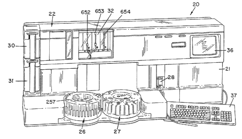
Referring first to FIGS. 1, 2 and 3, the automated analyzer of the present
invention and includes a housing 21 which contains or supports a plurality of
subunits
for performing the various steps for completion of a plurality of binding
assays on
fluid samples, e.g. blood serum. The analyzer is specifically adapted to
perform
heterogeneous immunoassays having various formats. The subunits include a
cuvette
hopper and feeder mechanism which is generally indicated by the reference
numeral
22, a cuvette conveying system 23, a sample probe transport system 24, a
plurality
of reagent probe transport systems Rl, R2 and R3, a sample transport system
which
is generally indicated by the reference numeral 26, and a reagent transport
system
which is generally indicated by the reference numeral 27. A detection device
29 is
located at the end of and above the conveyor system 23. The detection device
of the
preferred embodiment is a luminometer. Other devices, e.g. fluorimeter,
isotope
emitter counters, etc. are known in the arts. The uses of. such other devices
is
determined by the type of label that is utilized in a test reaction. This
system 20 also
includes a syringe bank 32, a central processing unit (CPU), not shown, which
is
2S operably connected to a cathode ray tube (CRT) 36 and keyboard 37. The
syringe
{20)
bank 32 is operatively connected to the sample probe transport system 24 and
reagent
probe transport systems Rl, R2 and R3.
A wash station for the sample aspirating and dispensing probe is located
behind the sample transport system and is generally indicated by the reference
numeral 18. Additional wash stations, generally indicated by the reference
numerals
15, is and 17, for the reagent aspirating and dispensing probes are located
behind the
reagent transport system 27, see also FIGS. 21A, 21B and 22.
Referring particularly to FIG 3, the conveyor system 23 is divided into two
sections, a cuvette preheater section which is generally indicated by the
reference
numeral 38 and a cuvette dispense and incubation section which is generally
indicated
by the reference numeral 39. The cuvettes 40 are stored in a random manner in
a
hopper 22 and conveyed to the end of the preheater section 38 in an upright
orientation. A plunger 19 is fixed to the end of a lead screw 41 which is
driven
horizontally by an electric motor 25 along its central longitudinal axis and
the axis of
the preheater section 38. The plunger 19 is moved from an' outer retracted
position
to an extended position as shown in FIG. 3 to push a cuvette which has just
been
deposited on the preheater section 38 one cuvette space towards the incubation
section
39. This advances all of the cuvettes 40 along the preheater section 38 so
that the
furthest cuvette is transferred onto the incubation section 39. The plunger
4~1 is then
moved back to the retracted position to engage the next cuvette which will
drop into
the starting position. The lead screw 41 does not rotate about its axis.
Cuvette
sensors, generally indicated by the reference numeral 43, are positioned at
the end of
the preheat section 38 and at the beginning of the incubation section 39 to
monitor the
presence of cuvettes at these locations. The cuvettes 40 are conveyed along
the
incubation section 39 by conveyor means, described below, which is driven by a
motor 42. As each cuvette reaches a sample dispense point 44 along the
incubation
(21)
section 39, a probe, described below, from the sample probe transport system
24
aspirates a predetermined amount of fluid to be analyzed from a container,
described
below, in the sample transport system 26 and deposits the sample in the
cuvette at the
sample dispense point 44. When the cuvette reaches any one of three
predetermined
S positions 45, 46 or 47 adjacent the reagent transport system 27, a pair of
reagents
from the reagent transport system 27 is added to the fluid sample in the
cuvette to
initiate a test reaction for form a detectable product by one or more of the
reagent
probes from the reagent probe systems Rl, R2 or R3. The sequence of reagent
addition into the cuvette is deteranined by the assay protocol selected for
the test
sample. Variation in reagent addition occurs for example when an incubation of
test
sample and one of the reagents is required. The reagents comprise a solid
phase
ieagent and a labeled reagent (tracer reagent) which, in the preferred
embodiment,
is of a luminescent compound.
The solid phase reagent in the preferred embodiment is paramagnetic particles
having a binding substance coupled thereto. Alternate solid phase materials
are
known in the arts as well as separation techniques for isolating the said
solid phase
materials. The detectable product that is formed in the preferred embodiment
is a
complex that includes the solid phase reagent, analyte that is being assayed
and the
labeled reagent. The complex will vary depending on the format of the assay.
Examples of binding assay formats which generate a detectable ,product include
competitive and sandwich type reactions, each of which may be performed by the
analyzer of the present invention. Thereafter, the cuvette passes an
aspirate/resuspend
area which is generally indicated by the reference numeral 28, which prepares
the
rtiixture for a "flash" or light emitting reaction in the luminometer 29.
Referring
particularly to PIG. 3, the aspirate resuspend area 28 of the preferred
embodunent
includes a magnetic apparatus 49. An aspirate/wash probe is located at point
50. An
CA 02050121 1998-09-17
(22)
aspirate probe is located at point S 1 and an acid resuspension probe is
located at point
S2.
When the cuvette reaches the end of the incubation section 39, it is lifted
vertically by an elevator mechac~ism at point S3 to the luminometer 29. When
the
S cuvette which contains the acid resuspended detectable product has been
properly
positioned within the luminometer, a base solution is added which results in a
chemiluminescent detection reaction ("flash"). The "flash" effects a
photomultiplier
tube which counts photons from the "flash" and produces an electrical signal.
The
signal is processed by the central processing unit and an appropriate value
reading is
recorded. Deionized water is used for a system backing fluid and for many of
the
washing steps for typical assay protocols and is stored in a removable
reservoir
30. A second removable reservoir 31 is located below the reservoir 30 for
accepting
all fluid waste. After each assay, the contents of the cuvette are aspirated
from the
cuvette and discharged into the fluid waste reservoir 31. The empty cuvette is
then
1S discarded into a waste receptacle 3S. Acid reagent is stored in a reservoir
33 and base
reagent is stored in a reservoir 34. An example of an acid reagent which is
suitable
for use with the present system is: O.1N. HN03,pH 1.0 with .59~ peroxide. An
example of a base reagent which is suitable for use with the present system is
0.2SN.,NaOH,pH 13, and ARQUAD. Variations in the concentration of the acid and
base reagents may be required depending on the chemiluminescent label. The
chemiluminescent label in the preferred embodiment is an acridinium ester.
?~~~'~.~v
(23)
Cuvette and Reagent Containers
Refernng to FIGS. 4-8, the cuvette which is used as part of the automated
analyzer of the present invention is generally indicated by the reference
numeral 40.
Cuvette 40 is generally rectangular in cross-section and consists of a bottom
wail 55,
S a pair of opposite broad side walls Sfi and a pair of opposite narrow
sidewalls 57. .
The cuvette 40 has an interior chamber which is accessed from a top opening
69. A
pair of flanges 58 extend outwardly from the broad sidewall 56 at the top of
the
cuvette. A pair of spaced teeth 59 extend outwardly from each broad sidewall
56 just
below the flange 58. The flanges 58 and teeth 59 are instrumental in enabling
the
cuvette to be conveyed and transported through the various subsystems of the
machine
20, as will be described hereafter. The cuvette can be made of polypropylene
.or
polyethylene which have been found to produce a more even light distribution
during
the subsequent.flash in the luminometer than other polymers which have been
tested
such as polystyrene. However, polypropylene has been found to be the preferred
material for obtaining reliahle results.
Referring to FIGS. 9-13, one of the tyvo types of reagent containers which are
utilized in the analyzer, is generally indicated by the reference numeral 60.
The
ccintainer 60 is utilized for carrying a labeled reagent (tracer reagent)
which is sp~;ific
for certain test protocols and comprises a main body portion 64 which has an
inner
chamber 61, a threaded neck portion 65 and a tog opening 62 at the upper end
of the
neck portion 65 which opens into the chamber 61. A skirt 63 extends outwardly
from
a point below the neck 65 and extends downwardly to a point just below the
main
body portion 64. The skirt 63 is spaced from the main body portion 64 and
consists
of three flat sides and one rounded side. The skirt 63 enables the container
60'to be
securely mounted on the reagent transport means, described below.
FIGS. 14 and 15 illustrate a caver for a container including the reagent
~.a~~,~':
container 60 which is generally indicated by the reference numeral 66 and
includes
a top wall 67 which has a plurality of slits 68 which cross at the center of
the top wall
67. The cover 66 is made of an elastomeric material such as natural or
synthetic
rubber which enables the cover to engage the top of the neck portion 65 of the
container 60. The cover 66 reduces evaporation of reagent from the container
60 and
the slits 68 enable a reagent aspirating anal dispensing probe to penetrate
the top wall
67 to access the reagent fluid within the container. The slits 68 all
intersect at the
center of the top wall 67 to form a plurality of pie-shaped flaps which
converge at the
center of the cover and give way when pressure is applied to the center of the
cover.
The bottom of the cover 66 has an outer annular flange 70.
FIGS. 16-20 illustrate a second reagent container which is used with flee
analyzer and which is generally indicated by the reference numeral 75 for
holding a
solid phase reagent. The container 75 has a generally cylindrical main body
portion
76 which has an inner chamber 77 which extends to a tog opening 78 above a
threaded neck portion 79. An annular skirt 80 extends outwardly from the main
body
portion 76 at a point just below the neck 79 and extends downwardly to a point
below
the main body portion 76, as shown most clearly in FTG. 19. A pail of fins 81
extend inwardly into the chamber 77 from the inner chamber wall as shown most
clearly in FIGS. 17 and 20. The fins 81 are utilized for agitating.the solid
phase
' 20 reagent within the container in a manner described below in connection
with the
reagent transport system 27. The top opening 78 is also sealed by the cover 66
by
inverting the cover so that the top wall 67 extends below the top opening 78
and
inside of the neck portion 79 so that the flange 70 of the cover rests on top
of the
neck portion 79.
CA 02050121 1998-09-17
(25)
~uvette Feed and Orientation Mechanism
Referring to FIGS. 24-31, the cuvette feed and orientation mechanism 22
comprises a hopper which is generally indicated by the reference numeral 87, a
feed
conveyor which is generally indicated by the reference, numeral 86, and an
orientation
chute which is generally indicated by the reference numeral 131. The hopper 87
is
preferably made of an optically clear plastic material. This makes it easier
for the
operator to determine when the level of cuvettes in the hopper is low whereby
the
hopper requires additional cuvettes. In addition, the elements which are below
the
hopper, see FIG. 30, are visible.
Referring particularly to FIGS. 25, 26 and 30, the left side wall of the
hopper
has a vertical opening 88 and a pair of spaced outer flanges 89 which extend
outwardly from the left side wall of the hopper on opposite sides of the
opening 88,
as shown most clearly in FIG. 25. An upper horizontal flange 83 extends
outwardly
from the left and rear side walls of the hopper. The forwardmost flange 89 has
an
opening 84 just below the top flange 83, as shown in FIG. 25. Referring also
to
FIG. 25, a pair of elongated reinforcing plates 82 are fastened to the outer
surfaces
of the outer flanges 89 by bolts 91. The bolts 91 are also utilized to fasten
the
hopper 87 to a pair of chain guide plates 90 which are mounted to a hopper
feeder
support 92 which is, in turn, .mounted on a base plate 93 by means of bolts
95. The
chain guide plates 90 are separated by a plurality of tubular spacers 97
through which
the bolts 91 extend. A support bracket 94 is also mounted on the base plate 93
and
is fastened to the side of the hopper feeder support 92 as shown in FIG. 24. A
support bar 96 is also mounted to the outside of the rear most plate 90 by the
bolts
91. A ball slide assembly 110 is mounted to -the support bar 96. A mixing, bar
mounting plate 111 is mounted to the ball slide assembly 110. An endless
conveyor
chain 98 is located at the vertical side opening 88 and extends around a lower
idler
CA 02050121 1998-09-17
(26)
sprocket 101 and an upper drive sprocket 100. The sprockets 100 and 101 are
mounted
on bushings 102 and are rotatively mounted on the hopper feeder support 92.
The
upper drive sprocket 100 is driven by a stepper motor 103 which is mounted on
the
support 92. One section of the. conveyor chain 98 is guided along grooves in
the
outer longitudinal edges of the guide plate 90 and is located between the
inner
surfaces of the flanges 89 which define the opening 88. A plurality of spaced
bars
99 are located on the outside of the conveyor chain 98 and slant downwardly
and
forwardly toward the event conveyor. The chain 98 travels upwardly from the
bottom of the hopper 87 at an angle from the vertical. An idler sprocket shaft
112
extends through the bushing 102 and rotates with the idler sprocket 101, see
FIGS.
26 and 27. The forward end of the shaft 112 is fixed to a cam wheel 113 so
that the
cam wheel 113 rotates with the idler sprocket 101 by means of a clamp 114. A
lever
arm 115 is pivotally mounted on a shaft 116 which is mounted in an adjusting
fixture
117 which is located at a notch 118 in the left hand edge of the hopper feed
support
92. The pivoted end of the lever arm 115 has a flanged bearing 122 which
enables
the lever to pivot freely on the shaft 116. The opposite end of the lever arm
115 has
a slot 121 which receives a pin 120 of a mixing block 109. The mixing block
109 is
fixed to the mixing block mounting plate 111 and has an upper surface 123
which
slants downwardly from back to front at the same angle as the bars 99. The
mixing
block 109 is parallel with the section of the conveyor 98 which travels
upwardly
along the vertical opening 88 of the hopper and is located adjacent the bars
99. A
ball bearing follower 119 is rotatively mounted on the lever arm 115 and rides
in a
cam slot, not shown, on the rear side of the cam wheel 113. As the cam wheel
113
rotates with the idler sprocket 101, the lever arm 115 oscillates about the
shaft 116.
The right hand end of the lever arm 115, as viewed in FIG. 24, moves up and
down
and in turn causes the mixing block 109 to move ug and down. The timing of the
(27) ~ ~::) ~~. ~a
upper movement of the block 109 is such that the block moves upwardly at the
same
rate as the upward movement of the conveyor chain 98. The cuvettfees are
stored in the
hopper 87 in a random manner. The mixing block 109 serves two functions. The
first function is to agitate the cuvettes within the hopper 87, and the second
function
S is to assist in guiding the cuvettes onto the bars 99, one cuvette per bar.
As the
cuvettes are carried upwardly by the bars 99, the ands of the cuvettes are
guided by
the inner surfaces of the flanges 89 to maintain the cuvettes in position on
the bars
99. As each cuvette reaches the opening 84, it slides forwardly along its
respective
bar 99 through the opening 84, see FIGS. 2S and 27, in the forwardmost flange
89
and falls into the orientation chute 131.
The orientation chute 13I, as viewed in FIGS. 24, 27 and 30, consists of a
left hand plate I29 and a right hand plate 132 which are connected together
try screws
139 and held in a spaced parallel relationship by a pair of spacer blocks 133.
Each
plate 132 and 129 lies an upper slide surface 134 which define, therebetween,
a slot
135 toward the event conveyor. The slide surfaces 134 extend at a downward
angle
from back to front and at a downward angle toward the slot 135. As each
cuvette 40
falls through the opening 84 from the conveyor chain 98 to the orientation
chute 131,
the bottom end of the cuvette falls into the slot 135 and the flanges 58 axe
supported
on the slide surfaces 134. This enables the euvette 40 to slide down the
surfaces 134
in a nearly upright orientation. The chute 131 is mounted to the hopper feeder
support 92 by a chute support bracket 130. A chute end plate I36 is attached
to the
front edges of the plates 129 and 132 by screws 137. The plate 136 stops the
downward slide of the cuvettes 40. The end plate 136 has a hole 147 for
receiving
a position sensor 148 which is mounted on a PC board 138. The PC board 138 is
mounted on the plate 136 by fasteners 149. The forward end of each slide
surface
l34 has a flat upper surface 127 for receiving a flat spring 128 which helps
to insure
X28)
that the cuvette remains in the slot 135 when the cuvette strikes the end
plate 136.
The forward end of the slot 135 has a widened portion ox access opening 141
which
is slightly greater in width than the distance between the outer edges of
flanges 58,
see FIti. 30. The access opening 141 between the plates 129 and 132 enables
the
cuvette to fall between the plates into the orientation tube 140. The cuvette
falls
between a pair of opposed guide surface 142 and 143 along the inwardly facing
surfaces of the plates 129 and 132, respectively. The guide surface 143 has an
upwardly facing jutting surface I44. The guide surface 142 has a recessed
portion
145 which forms a downwardly facing undercut surface 146. The undercut surface
I46 is opposed to the jutting surface 144 of the plate 132. The orientation
tube 140
has a top opening 150 and a bottom opening 151 and extends from the bottom of
the
orientation chute 131 to the top of the preheater section 38. When the cuvette
falls
into the access opening 141 at the end of the orientation chute, one of the
flanges 58
of the cuvette strikes the jutting surface 144: This deflects -the cuvette
laterally toward
the recessed portion 145 of the left hand plate 129. As tha cuvette shifts
laterally, the
opposite flange of the cuvette strikes the recessed portion 145 just below the
. ~ downwardly facing undercut surface 146. This traps the flange of the
cuvette below
the undercut portion 146 and prevents the cuvette from accidentally flipping
upside
down when it reaches the end of the chug 13I. The cuvette, thereafter, falls
in an
upright orientation along the guide surface 142 and 143 into the orientation
tube 140
through the top opening 150 and through the bottom opening 151 into the
preheater
section 38. The orientation tube 140 has a helical twist which causes the
cuvette to
rotate approximately 90° about its vertical axis so that when the
cuvette falls inta the
preheater section 38, the braad sides 56 of the cuvette are forward and back
as well
as the flanges 58.
6'3
r
~.. rr
(29)
Referring to FICi. 29, the pre!heater section 38 comprises a pair of spaced
horizontal bars 1S8 and 1S9 which deifine therebetweeaa a vertical slot 160.
Each of
the bars 1S8 and 1S9 has a top edge i61. When a cuvette falls from the bottom
of
the orientation tube 140, the body of flee cuvette falls into the slot 160 and
the flanges
S S8 rest on the top edges 161. Plunger 19 is moved to its extended position
into the
slot 160 by the motor 2S from left to right as viewed in FIGS. 3, 32 and 33.
The
plunger 19 is moved from Heft to right a distance which is approximately or
slightly
more than a cuvette width which pushes all of the cuvettes in the preheater
section
toward the cuvette dispense and incubation section 39. The plunger 19 is then
retracted by the motor 2S to allow a subsequent cuvette to fall from the
orientation
tube 140 into the preheater section 38. The motor 2S is activated to
reciprocate the
plunger 19 once every twenty seconds or when a test is r~uested. The cuvettes
are
deposited into the orientation tube 140 at a faster rate than they are pushed
along the
preheater section 38 so that the tube 140 becomes full of cuvettes as
generally shown
in dotted lines in FiG. 29. The sensor 148 is a reflective object sensor which
indicates the presence of a stationary cuvette when the tutee is full. The
sensor 148
forms part of the overall analyzer control system and is effective to stop the
motor
103 when the sensor senses a stafionary cuvette at the tap of the orientation
tube.
The software which is used to control the instrument keeps track of the
cuvettes as
they are subsequently used oui of the orientation tube and controls when the
stepper
motor 103 is reactivated. The preheater section 38 contains a thermistor for
controlling a pair of solid state DC driven thermo-electric modules (TE1~,~Is)
which
maintain the temperahire of the preheater section at a set temperature of 37'
C. TEMs
are also known as thermoelectric cooling couples which are used to maintain a
2S predetermined temperature by transferring heat from one mass to another.
The
transfer of heat is reversed by reversing the direction of current flow. The
machine
(30)
framework provides a heat sink for the pre-heater section 38. When the
temperature
of the pre-heater section is below the set temperature, heat is transferred
from the
machine framework to the pre-heater section 38. When the set temperature of
the
pre-heater section is above the set temperature, as detected by the.
thermistor, the
current through the TEMs is reversed and heat is transferred from the pre-
heater
section 38 to the machine framework. The cuvette dispense and incubation
section 39
is also provided with a thermistor at two spaced strategic locations. Each
thermistor
controls a pair of thermo-electric modules (also strategically placed) for
maintaining
the cuvette temperature at 37' C. throughout the chemistry event line. In the
particular embodiment shown, the preheater section 38 holds seventeen cuvettes
and
the cuvette dispense and incubation section 39 holds forty-five cuvettes.
Referring particularly to FIGS. 32 and 33, the track section 23 is shown in
greater detail. The entire track section, including the preheater section 38
and the
dispense and incubation section 39, is covered by a top plate 162 which . has
a
plurality of access openings at the dispense points 44, 45, 46 and 47. The
plate 162
has an opening 186 at the sample dispense point 44 as shown in FIG. 33A. The
plate
162 has openings 187 and 188 for the reagent dispense points 45 and 46,
respectively,
as shown in FIG. 33B and an opening 189 for the reagent dispense point 47 as
shown
in FIG. 33C.
Referring particularly to FIG. 32A, the plunger 19 (not shown) has a tab 154
which extends horizontally toward the motor 25. When the plunger is ire the
outer
or retracted position, it extends between a pair of spaced components of an
interruption sensor 155. The sensor 155 has a photo transmitting portion which
directs a beam toward a photo receiving portion. When the beam is interrupted
by
the ta5 154, a signal is transmitted to the CPU to indicate that the plunger
is ac the
"home" position. (After a predetermined time period or when another test is
CA 02050121 1998-09-17
(31)
requested), the stepper motor 25 is actuated for a predetermined number of
steps to
move the plunger 19 a predetermined distance out to the extended position. The
motor is then reversed to bring the plunger back until the sensor 155 is
interrupted
by the tab 154 at the "home" position. All of the "interrupter" sensors
described
hereinafter are connected to the CPU through the machine controller board and
operate in the same manner as the sensor 155. The cuvettes are pushed along
the
preheater section 38 and into the cuvette dispense and incubation section 39,
at which
point they are positively conveyed by a pair of conveyor belts 167 and 168.
Each of
the conveyor belts 167 and 168 has a plurality of teeth 164 on one side of the
belt for
engaging the teeth 59 of the cuvettes. A stepper motor 42 has a drive shaft
181
which is rotatedlin a clockwise direction when viewed from the front. The belt
168
is driven by the motor 42 through the toothed drive pulley 170 which is
located
between and below a pair of idler pulleys 171 and 179. The belt 168 extends
over
the pulley 179 to and around an idler pulley 178 at the beginning of the
incubation
section 39. The belt 168 then travels along the front edge of the incubation
section
39 to an idler pulley 172 at the end of the section 39 and then back over the
idler
pulley 171 to the drive pulley 170. The teeth 164 of the belt 168 face
upwardly as
the belt 168 extends around the drive pulley 170 and the idler pulleys 171 and
179
so that the teeth 164 of the belt engage the teeth of the drive pulley 170. As
the belt
travels to the pulley 178, it gradually assumes a vertical orientation so that
the teeth
164 face forwardly. As the belt extends around the pulley 178 and travels
along the
front edge of the dispense and incubation section 39, the teeth 164 face
rearvvardly
and, thereby, engage the flanges 58 of the cuvettes. The belt 168 continues in
a
vertical orientation around the idler pulley 1'12 and gradually reassumes its
horizontal
orientation as it reaches the idler pulley 171. The pulleys 179 and 171 are
rotatably
mounted on horizontal shafts 182 and 183, respectively. The pulleys 178 and
172 are
~~~~,~.~~~.
~3~)
rotatably mounted on vertical shafts 180 and 184, respectively. The drive belt
167 is
located on the rear side of the dispense and incubation section 39 and is
driven
longitudinally by a drive pulley 175 which is fixed to the drive shaft 181.
The drive
pulley 175 has external teeth 191 and is located between and below idler
pulleys 174
and 176. The belt 167 extends over the idler pulley 176 which is rotatively
mounted
on the horizontal shaft 182 and around an idler pulley 177 which is rotatively
mounted on a vertical shaft 190. The belt 167 then extends along the back side
of
the cuvette dispense and incubation section 39 to and around an idler pulley
173
which is rotatively mounted on a vertical shaft 185. The belt 167 then extends
over
the idler pulley 174 which is rotatively mounted on the horizontal shaft 183
and back
to the drive pulley 175, The belt 167 has a plurality of teeth 193 on one side
of the
belt. The teeth 164 on the belt 167 face upwardly as the belt 167 extends
over.the
,.r idler pulley 174 and under the drive pulley 175 and back up around the
idler pulley
176. The teeth 193 of the belt 167 are in drive engagement with the teeth 19i
of the
drive pulley 175. When the belt 167.travels between the pulley 176 and the
pulley
177 it gradually assumes a vertical orientation so that the teeth 193 face
forwardly as
the belt travels along the aspiration and incubation section 39 W the idler
pulley, x73.
As the inner sections of the belts 167 and 168 travel from left to right as
viewed in
Fl:(iS. 32 and 33, the rearwardly facing teeth of the belt 168 and the
forwardly facing
teeth of the belt 167 engage the flanges 58 of the cuvettes 40 to advance the
cuvettes
along the event track or dispense and incubation section 39 for a
predetermined time
period during the twenty second system cycle.
(33)
~~ple Transport S sir tem
The sample transport system consists of a sixty position sample tray for
receiving sample containers containing test samples, calibratars, controls,
and
diluents; a laser bar code reader.; and a digital diluter. The sample tray
consists of
two concentric rings, each capable of holding a nuxed population of various
tubes and
sample containers. The outer ring can accommodate thirty-four sample
containers,
the inner ring twenty-six sample containers. Fach position has a spring clip
so that
different sizes of sample containers can be accommodated. The bar code reader
recognizes six versions of bar code language, and recognizes the identity of
each bar
coded sample and the identity of the bar coded tray. The operator may program
the
analyzer to automatically repeat any sample whose inikial test result exceeds
a selected
range. Also, for most assays, the system will automatically dilute and re-
assay any
sample above the range of the standard curve, if desired. Various dilution
ratios are
selectable, based upon sample size. The sample aspirating and dispensing probe
as
specially coated and has capacitance level sensing in order to recognize the
surface
of the sample. This insures that liquid is present in a sample container
before
aspirating, as well as minimizing immersion into the test sample. After each
aspiration and dispensing cycle, the inner and outer surfaces of the probe are
thoroughly washed with deionized water at a wash station to minimize sample
carryover.
The sample transport system 2b is shown in F1G~. 36-42. Referring first to
FIGS. 38, 39 and 41, the transport system 26 includes a fixed base which is
generally
indicated by the reference numeral 211 and which is mounted in a fixed
position on
the machine framework in front of the cuvette dispense and incubation section
39.
The fixed base 211 includes an upper horizontal plate 212 and three descending
legs
213, each with a horizontally and outwardly extending foot portion 214. Each
foot
CA 02050121 1998-09-17
(34)
portion 214 supports a roller 247 which is rotatively mounted on a horizontal
shaft
215 for rotation about a horizontal axis. Each foot 214 also supports a roller
218
which is rotatively mounted on a vertical shaft 217 for rotation about a
vertical axis.
An electric stepper motor 219 is faced to the bottom of the upper plate 212
and has
S a drive shaft 220 which extends through a hole 216 in the upper plate 212. A
friction
drive wheel 221 is fixed to the outer end of the shaft 220 for rotation
therewith. An
inner tray, generally indicated by the reference numeral 222, and an outer
tray,
generally indicated by the reference numeral 223, are rotatively mounted on
the base
211 for rotation independently of one another about a vertical axis 209.
The inner tray-222 includes an inner hub portion 225 which is rotatively
mounted on a vertical shaft 224 which is fixed to the upper plate 212 and
which
extends along the vertical axis 209, see FIG. 38. The inner hub portion .225
has a
downwardly extending annular flange 226 which is in frictional engagement with
the
drive wheel 221. When the motor 219 is actuated, the drive wheel 221 is
rotated by
the shaft 220 which, in turn, rotates the inner hub portion 225 about the axis
209 due
to the frictional engagement of the roller 221 against the inner surface of
the annular
flange 226. The inner hub 225 has an outwardly extending circular flange 208
at the
bottom of the hub. The flange 208 is rotatably supported on the rollers 247.
The
inner tray 222 also includes an outer hub 227 which has an outer annular
flange 228
which supports a plurality of receptacles 229 for supporting a plurality of
sample
containers, see FIG. 37. The receptacles 229 are arranged in a circle which is
concentric with the axis 209. Each receptacle 229 has an outwardly facing
opening
195.
The outer tray 223 includes a drive ring 230 which has an outer downwardly
extending annular flange 231. The annular flange 231 has an inwardly facing
annular
groove 232 for receiving the rollers 218 which support the drive ring 230 for
rotation
~fl j~~.~~.
about the axis 209. The drive ring 230 supports an outer r'mg 233 which
contains a
plurality of upwardly extending receptacles 234 for supporting a plurality of
sample
containers. The receptacles 234 are arranged in a circle which is concentric
with the
axis 209 and is located outside of the circle of receptacles 229 as shown in
FIG. 37.
Each receptacle 234 has an outwardly facing opening 260. Each of the
receptacles
229 and 234 is at least partially tined with a metal plate 270 which has a
plurality of
inwardly protruding resilient fingers 271. The fingers provide a snug fit for
a test
tube or sample container and enable test tubes of different diameters to be
used and
held securely. The plates 270 and fingers 271 also provide a ground connection
to
the metallic machine framework to provide one component of. a capacitance
level
sensing system to be described in a later section entitled: "SAMPLE PROBE
TRA1~TSPOH.T SYSTEM". The outer tray 223 is rotated independently of the inner
Ys tray 222 by means of a stepper motor 235 which is fixed to a mounting plate
236
which is, in turn, supported on the framework of the machine.. The stepper
motor
235 has a drive shaft 237 which is fixed to a drive pulley 238. A pulley 239
is fixed
to a vertical shaft 241 which is mounted for rotation on the plate 236. The
pulley
239 is driven from the pulley 238 by a timing belt 240. A drive wheel 242 is
faxed
to the pulley 239 and is in frictional engagement with the outer surface of
the flange.
231. When the motor 235 is activated, the roller 242 is rotated about the axis
of the
shaft 241 which, through its frictional engagement with the outer surface of
the flange
231, causes the drive ring 230 to rotate about tire axis 209. This rotation is
totally
independent of the rotation of the inner tray 222 by the stepper motor 219.
Referring to FltiS. 40 and 42; a PC board 245 is mounted to the machine base
. . adaacent the sample transport system 26. The PC board 245 supgorts a
plurality of
interrupt sensors for the inner and outer trays. The sensors are arranged in
two
groups, an outer group for the outer ring, and an inner group for the inner
ring. The
CA 02050121 1998-09-17
(36)
outer group includes a pair of spaced outer sensors 246 and an inner home
sensor
266. The inner group includes a pair of inner sensors 244 and an inner home
sensor
267. The outer ring 230 has a single downwardly descending home tab 253 which
interrupts the beam of the home- sensor 266 to determine a starting position
for the
S outer ring at the beginning of a test or a series of tests. A plurality of
tabs 268
extend downwardly from the drive ring 230 of the outer tray 223 outside of the
home
tab 253 and extend in a circle about the axis 209. As the outer ring rotates
about the
axis 209, the tabs 268 pass through both sets of sensors 246. There is a tab
268 for
each sample position- of the ring 230 so that each time that the ring is
rotated one
position, the beam in each of the sensors 246 is interrupted to provide a
signal to the
CPU to indicate that the outer tray 223 has moved one position. The distance
between the two sensors 246 differs from the spacing between two adjacent tabs
268
so that the sensors are not interrupted simultaneously. This enables the
control
electronics to determine the direction of rotation of the ring 230. To
position a
particular bottle or sample container about the axis 209, a command is given
to the
stepper motor 235 to move a number of steps in a certain direction and
acceleration.
The optical interrupt sensors 246 count the number of positions moved by the
drive
ring 230 to determine the final desired position of the ring. When the correct
number
of transitions have occurred, the stepper motor 235 will move a calibrated
number of
steps past the transition point and stop. This will be the final container
positioning
point. The CPU is programmed to move the ring 230 and outer tray 223 in
whichever direction will result in the smallest amount of rotation of the ring
for each
new sample container position. A single "homes tab 269 extends downwardly from
- . the inner tray 222 for interrupting the beam of the home sensor 267 to
determine the
starting or "home" position of the inner tray. A plurality of tabs 243 extend
downwardly from the tray 222 outside of the "home" tab 269 and extend in a
circle
cs7>
which concentric with the axis 209. 'rhe tabs 243 interact with the interrupt
sensors
244 for controlling the stepper motor 219 and selectively positioning the
inner tray
222 in the same manner as the tabs 268 and sensors 246 are utilized to
selectively
position the outer tray 223. The inner and outer trays are moved selectively
and
independently to position a specified predetermined sample container to a
predetermined pickup position for aspiration by the sample aspirating and
dispensing
probe 24. Referring to FIG. 22, the pickup position for the outer tray is
located at the
opening 255 in the outer cover 257. The pickup position for the inner tray is
located
at the opening 256 in the outer cover 257. A bar code label is affixed to the
outer
wall of each sample container. 'The label has a specific bar code which
identifies the
test sample within the container. All of the information relating to the
sample, such
as the name of the patient and the tests which are to be performed with the
sample,
are stored within the memory of the central processing unit. Referring to FIG.
22,
a bar code reader 258 is located adjacent the sample transport system 26 and
has two
lines of sight which are indicated by the dotted lines 259 and 272. Prior to a
run. of
tests, the receptacles in the inner and outer trays are charged with sample
containers
each containing its own specific bar code which can be viewed through the
openings
260 in the outer parts of the receptacles 234 and the clear plastic cover 257,
The
outer tray 223 is rotated about the axis 209 so that each sample container
passes
through the lines of sight 272 and 259 relative to the bar code reader 258 so
that the
bar code on each sample container can be read by the bar code reader. The
energy
beam from the transmitting portion of the bar code reader 258 passes along the
line
of sight 272 and the beam is reflected back from the bar code label on the
sample
container along the line of sight 259 to the beam receiving portion of the bar
code
reader. The vertical openings 260 and the transparency of the outer cover 257
enable
the bar codes on the samples to be "seen" by the bar code reader. This enables
the
6~ f.
7J
{38)
identity of each sample container to be correlated with the position of the
outer tray
relative to a home position. After all of the sample containers have been read
by the
bar code reader, the outer tray 223 is positioned so that a gap 261 in the
circle of
receptacles 234 is aligned with the lines of sight 259 and 272. This enables
the bar
codes on the mmple containers in the inner tray 222 to be exposed through
openings
195 in the outer portions of the receptacles 22,9 to the bar code reader 258.
The inner
tray 222 is rotated so that each sample container in the inner tray passes
through the
lines of sight 259 and 272 so that the specific bar code of each sample in the
inner
tray 222 is read by the bar code reader. This information is utilized by the
central
processing unit to correlate the position of each sample container in the
inner tray 222
relative to the home position of the inner tray.
Referring particularly to FIGS. 39 and 41, a contact ring 250, is fastened to
the drive ring 230 by a screw 262 which also mounts a positioning key 263 to
the
drive ring 230. A contact ring. 252 is fastened to the upper wall of: the hub
.225 by
a screw 264. Positioning key 265 is fixed to the hub 225 at the base of the
flange .
226. The metal grounding wire 248 is connected to the contact ring 252 and
connected to the keys 265 and 263 by a connecting wire 249. These elements
form
part of the grounding system for grounding the fingers 271 to the machine
fc~mawork.
The bar code-labeled sample containers may be loaded in any order in the
sample tray. The analyzer will read all bar codes automatically, and identify
the
sample and its position in the tray. If bar code labels are not used, a
worklist printout
is utilized, which directs placement of samples in specific sample tray
positions.
CA 02050121 1998-09-17
(39)
Reagent Transport S3rstem
The reagent transport system or tray provides a carrier for twenty-six reagent
bottles or containers, sufficient for up to thirteen different assays. The
inner portion
is made to specifically accept the solid-phase reagent containers, and
periodically
agitates these containers to maintain homogeneity of the solid phase reagent.
This
mixing action is aided by the design of the reagent bottles, which have
agitator fins
molded into their inner walls. The tracer or labeled reagent bottles are also
specially
shaped to automatically orient the identifying bar code label affixed to the
container,
and are loaded into the outer positions on the reagent tray. Reagents are bar
code
labeled. A reagent laser bar code reader records the loaded position of each
specific
reagent, including identity and lot number, making random loading permissible.
Reagents may be loaded directly from refrigerated storage, since they are
warmed to
37' C. before dispensing. The three reagent aspirating and dispensing probes
have
capacitance level sensing and may be programmed to make an initial reagent
level
check before starting an assay run to insure that adequate reagent volumes
have been
loaded to complete the scheduled worklist stored in the CPU. Reagent volumes
used
range from 50-450 uL, depending on the assay, and specific reagents may be
added
to the sample in the cuvette by each of the three reagent probes, with
incubation times
of 2.5 to 7.5 minutes, depending on optimal condition for specific assays.
Reagent
probes, like the sample probes, are thoroughly washed with deionized water
between
dispensings.
Referring to FIGS. 43-49, the reagent transport system is generally indicated
by the reference numeral 27. The reagent transport system 27 comprises a fixed
supporting base 286 which is fixed to the machine framework 283 and an
electric
stepper motor 287 which is fixed to the supporting base 286 by fasteners 282
and
connecting rods 285. The stepper motor 287 has a drive shaft 290 which is
fixed to
CA 02050121 1998-09-17
a motor hub 291 by a trantorque clamp 280. The drive shaft 290 is rotated
about a
vertical drive axis 293. The base of the motor hub 291 consists of a ring of
upwardly
facing gear teeth 292. The circular spill tray 288 has a central circular
opening 289
and is fixed to the supporting base 286 by a plurality of fasteners 279 so
that the
stepper motor 287 extends upwardly through the opening 289. Referring to FIGS.
45 and 46, a support ring 294 is located concentrically of the central
vertical axis 293
and has a central circular opening 295 and a plurality of smaller openings 308
which
are arranged in a circle which is concentric with the axis 293. A reagent tray
296 is
mounted on the support ring 294 and contains a ring of inner pockets 297 and a
ring
of outer pockets 299. The pockets 297 and 299 are arranged in concentric
circles
about the axis 293. Each outer pocket 299 contains a tubular outer bottle or
reagent
container holder 298 which is fixed to the pocket by a fastening disc 301. The
connector 301 extends through an aperture 302 at the base of the pocket to the
support ring 294 for fastening the reagent tray 296 to the ring 294. When a
container
60 of labeled or tracer reagent is placed in the pocket 299, the tubular
holder 298
extends between the skirt 63 and the main body portion 64 as shown in FIG. 45.
Each inner pocket 297 contains an inner container holder 300. A fastening
disc 303 bears against the bottom wall of the holder 300 and has a vertical
shaft 304
which extends through an opening in the bottom wall of the holder. The
fastening
discs 301 and 303 are metallic and are grounded to the machine framework. The
discs 301 and 303 provide one component of a capacitance level sensing system
which
is described in a following section entitled °REAGENT PROBE TRANSPORT
SYSTEM°. A gear 306 is fastened to the bottom of the holder 300 by a
pair of
screws 305 which also effectively clamp the fastening disc 303 and the gear
306
against the bottom wall of the holder 300. The bottom of the shaft 304 extends
below
the gear 306 and into a pair of flanged bearings 307 which are mounted in one
of the
_%. ~d . .
(41)
apertures 308 of the support ring 294. This enables each holder 300 and its
respective gear 306 to rotate about its own central longitudinal secondary
axis 278.
The gears 306 extend about a ring gear 309 and are in driving engagement with
the
outer. teeth of the ring gear, see F1G. ~k6. The ring gear 309 has a large
central
opening 277. A pair of pins 310 are fixed to the gear 309 and extend below the
gear
into driving engagement with the teeth olf the ring gear 292, see FIG. 45.
Actuation
of the stepper motor 287 causes the hub 291 in the ring gear 292 to rotate
about the
axis 293. This causes rotation of the ring gear 309 through the drive pins
310. The
ring gear 309, in turn, drives all of the satellite gears 306 for rotating
each bottle
holder 3~ about its respective secondary axis 278. The ring gear 309 is fully
supported by the satellite gears 306. A plurality of retainers 311 are fixed
to the ring
gear 309 and extend below the gear 309 for straddling the inner edge of the
support
ring 294. The bottle holder 300 holds a solid phase bottle or reagent
container 75.
The side walls of the holder 3~ has a plurality of vertical slots 276 which
form a
plurality of resilient fingers 274 which extend between the main body 76 and
the skirt
80 of the reagent bottle or reagent container 75 for holding the reagent
container 75
in a friction fit. The .stepper motor 287 is reversible and controlled by the
central
processing unit to oscillate the drive shaft 290 at predetermined intervals.
Each of the
bottle holdees 300 is adapted to receive a solid phase reagent container 75.
The
oscillations of flee holder 300 provide the necessary motion to the reagent
container
75 for enabling the fins 81 to agitate the solid phase reagent solution within
the bottle
75 and, thereby, maintain a uniform concentration of the solid phase elements
within
the solution. Each of the bottle holders 298 is adapted to receive a labeled
reagent
container 60 which does not require agitation. Referring particularly to FIGS.
45 and
47, a ring gear 312 encircles the spill tray 288 and is mounted for rotation
on the
supporting base 286 about the axis 293. The lower part of ring gear 312 has an
~rJ~.~~
(42)
inwardly facing V-shaped bead 27S which engages a plurality of V-guide wheels
323
which support the ring 312 for rotation about the axis 293. Each wheel 323 is
rotatively mounted on a vertical shaft 324 which is fixed to the base 286. The
ring
gear 312 supports the support ring 294 and the reagent tray 296. Referring
also to
FIGS. 48 and 49, part of the ring gear 3112 has an annular flange which is
opposite
the V-shaped beads 2?S and contains a ring of outwardly facing gear teeth 329
which
are in driving engagement witti an idler gear 319 which is keyed to a vertical
shaft
320. The shaft 320 is rotatively mounted in flanged bearings 321 which are
supported on flanges 322 of a motor mount 314. The motor mount 314 has a
circular
bore 316 which contains a drive gear 318 which is fixed to the drive shaft 317
of a
stepper motor 315. The stepper motor 31S is fixed to the motor mount 314. The
wall of the bore 316 of the motor mount 314 has a lateral opening which
enables the
drive gear 318 to engage the idler gear 319. Actuation of the motor 31S causes
the
drive gear 318 to drive the ring gear 312 through the idler gear 318 about the
vertical
1S axis 293. The inner and outer pockets 297 and 299, respectively, are
enclosed within
a clear stationary plastic covers 327. The cover 327 has a plurality of
openings 328, .
338, 339, 340, 341, and 342 which provide access to the bottles within the
pockets
297 and 299 by reagent aspirating and dispensing probes to be described in a
later
section, see FIG. 22.
Referring to FIG. 47, a PC board 330 contains a pair of interrupter sensors
331 and 336 and a photo reflector sensor, not shown, which is located beneaih
the
sensors 331 and 336. The optical reflector sensor has a beam transmitting
portion and
beam receiving portion. If a beam from the transmitting portion strikes a
reflective
surface, the beam is reflected back to the receiving portion of the sensor.
When the
beam is not reflected back, the sensor generates a signal to the CPU. The PC
board
330 is mounted to the base plate 286 so that the sensor optical reflector
faces
3 1 (~
1~~~ ~~l.~a.~~.
(43)
outwardly toward the ring 312. The beams from the transmitting portion of the
beam
reflector sensor strikes the ring 312 and is reflected back to the beam
receiving
portion of the sensor. The ring 312 has an aperture 326, see FIG. 49, which is
at the
same level as the beam from the photo reflector sensor. At the beginning of a
testing
sequence, the ring 312 is rotated about the axis 293 until the beam of the
photo
reflector sensor is aligned with the ~apertwre 326. When this occurs, the beam
passes
through the aperture and is not reflected back to the sensor. The absence of
the
reflected beam initiates a signal to the CPU to indicate the "home" or
starting position
of the reagent tray at the beginning of a series of tests. Referring to FIG.
47, the
ring 312 has a plurality of tabs 334 which extend inwardly from the ring 312
and
which pass between the two spaced elements of each interrupter sensor 331 and
336
for interrupting a beam from each optical sensor which provides feedback to
the
control electronics for reagent bottle positioning. There is a tab for each
reagent bottle
position in the tray 296 so that each time that the ring is rotated one
position, the
beam in each of ttte sensors 331 and 336 is intemipted to provide a signal to
the CPU
to indicate that the tray has moved one position. The distance between the two
sensors is less than the spacing between two adjacent tabs 334 so that the
sensors 331
and 336 are not interrupted simultaneously. This enables the CPU to determine
the
direction of rotation of the reagent tray. To position a particular bottle or
container
to a reagent probe pickup or aspiration position, a command is givers to fhe
supper
motor 315 to move a fixed number of steps in a certain direction, This causes
the
reagent tray 296 to rotate along with the tabs at the bottom of the drive ring
312.
The sensors 331 and 336 counts the number of tab transitions and_ determines
the
position of the reagent tray 296. When the correct number of transitions have
occurred, the stepper motor 315 will move a calibrated number of steps past
the
transition point and stop. The bottle containing the designated reagent will
thereby
(44)
be positioned at the predetermined pickup point for one of the reagent probes.
A photo reflective sensor 337 is mounted on the plate 286 and directs a light
beam upwardly. The motor hub 291 has a bottom reflective surface which has a
plurality of spaced apertures, As the hub 291 oscillates, the beam from the
sensor
S 337 is alternately reflected back to the sensor by the bottom reflective
surface of the
txub and absorbed by the apertures in the bottom surface, This provides
appropriate;
signals to the CPU to indicate that the hub is being oscillated at
predetermined
intervals.
Each reagent container has a bar code label affixed to its outer skirt
portion.
The label contains a specific bar code which identifies the reagent within the
container. The information relating to all of the reagents in the bar codes
associated
with the reagents are stored within the memory of the central processing unit.
Referring to FIGS. 43 and 22, a bar code reader 332 is located adjacent the
reagent
transport system 27. The bar code reader 332 transmits an energy beam along a
line
1S of sight which is indicated by the dotted line 333. The beam is reflected
back go the
bar code reader 332 from the bar code label along a line of sight which is
indicated
by the dotted line 344. The return beam along the line of sight 344 is
received by
the beam receiving portion of the bar code eeader. The bar code in the
preferred
embodiment is printed on the label for each reagent bottle in a vertical
direction. The
inner pockets 297 and outer pockets 299 are staggered with respect to each
other. As
the reagent tray 27 is rotated about the axis 293 by the stepper motor 315,
the inner
and outer pockets alternately pass through the lines of sight 333 and 334 of
the bar
code reader 332. The stepper motor 287 is also utilized during the initial
reading of
reagent container bar codes pcior to a run of tests. Referring ~to F1GS. 43
and 46,
there is a relatively large space between each outer pocket 299. Each inner
pocket 297
is horizontally aligned with the space between two adjacent pockets 299. A
vertical
(45)
waft 335 which separates the inner and outer pockets 297 and 299,
respectively, has
a relatively large opening 328 at each space between cuter pockets 299 so that
each
reagent container is exposed to the line of sight of the bar code reader when
the
container is rotated about the axis 293 by the stepper motor 315. As the
reagent tray
2? is rotated about the axis 293, each reagent container or bottle in the ring
of inner
pockets 297 is given one and one-half revolutions per pass of a reagent
container 7S
through tile lines of sight 333 aiid 334 to insure that the bar code is
exposed to the
reader. The bar codes on the bottles in the inner and outer pockets can be
read by
the bar code reader 332 through the clear plastic cover 32?.
l0 The operator loads required assay reagents, in original bar code-labeled
bottles, into the reagent tray in any order; solid-phase reagents on the inner
bottle
holders 300, labeled or tracer reagents on the outer bottle holders 298. Due
to the
design of the reagent bottles, it is not possible to mis-load reagents. . The
analyzer
will read ail bar codes before initiating a run, identifying each reagent, its
position,
its lot numher and expiration date. if greater than 50 tests of a specific
assay has
been requested in the worklist, multiple bottles of the necessary reagents may
be
loaded on the reagent tray and the analyzer will access them sequentially, as
needed:
(46)
~arr~ple Probe Transport System
Referring to FrGS. 50-59 and first to FIGS. 54 and SS, the sample peobe
transport system 24 comprises a fixed upper horizontal support plate 357, and
a
sample probe supporting carriage, generally indicated by the reference numeral
363,
S which is mounted for horizontal back and forth movement relative to the
supporting
plate 357. The support plate 357 has an opening 366. A PC board 3S8 is fixed
to
the upper surface of the plate 357 by screws 359. The under surface of the PC
board
has a plurality of electrical junctions J1, J2; J3, J4 and JS which extend
into the
opening 366. A vertical bracket 364 is fixed to the underside of the plate 3S7
at the
rear end of the plate. An electrical stepper motor 36.5 is fixed to the
forward side of
the bracket 364 and has a drive shaft 369 which is rotatable about a
horizontal axis.
A lead screw 371 is fixed to the drive shaft 369 through a drive coupling 370
and
extends through a roll nut 409 which is fixed within a bore 408 of a block
372. (See
also FIG. S8.) The block 372 is mounted in a yoke 373 between a pair of upper
and
lower dowel pins 374. The dowel pins 374 enable the block 372 to pivot about a
vertical axis to compensate for slight misalignments between the block 372 and
the
lead screw 371. The block 372 has a laterally extending horizontal shaft 375
which
is mounted to the carriage 363 in a manner described herein below.
A guide bracket 360 is fixed to the underside of the plate 357 by the screws
3S9 and has a downwardly facing horizontal groove 361. A carriage supporting
bar
362 is slidably mounted in the groove 361. The carriage 363 is fixed to the
sliding
bar 362 by a screw 391 and an anti pivot rod 387 which has a threaded upper
end.
The carriage 363 includes a forwardly facing vertical wall 376, a top
horizontal wall
377 and a lover horizontal wall 378. The top wall 377 has an aperture 389 and
the
2S bottom wall 378 has an aperture 388. The anti pivot rod 387 extends freely
through
the apertures 388 and 389 and is threaded into the block 362. Referring also
to FIG.
CA 02050121 1998-09-17
(47)
56, the wall 376 has a horizontal bore 379 which has a bearing 380 at each end
of the
bore. The shaft 375 of the yoke 373 extends through the bore 379 within the
bearings 380. A vertical lead screw 385 is rotatably mounted in upper and
lower
bearings 383 and 384, respectively, in the upper and lower walls 377 and 378,
respectively. The lower end of the lead screw 385 extends below the bottom
wall 378
and is fixed to a pulley 386. An electrical stepper motor 394 is fixed to the
underside
of a rearwardly extending horizontal flange 393 of the carriage 363. The
stepper
motor 394 has a vertical drive shaft 395 which is fixed to a pulley 396, see
also FIG.
57. The pulley 396 is drivingly connected to the pulley 386 through a timing
belt 397.
The inner surface of the timing belt 397 has a plurality of teeth for engaging
corresponding teeth on the drive pulleys 396 and 386, (teeth not shown). A
lead
screw follower 401 is positioned between the walls 377 and 378 and has a
vertical
bore 403 and a vertical bore 404 which contains a roll nut 405 (see also FIG.
59).
The anti pivot rod 387 extends freely through the bore 403 and the lead screw
385
extends through the roll nut 405. The roll nut 405 is fixed relative to the
follower
401 so that as the lead screw 385 is rotated about its vertical axis, the
follower 401
moves along the central longitudinal axis of the lead screw 385 relative to
the walls
377 and 378. A probe holding arm 402 is fixed to the forward end of the
follower
401 and carries an aspirating and dispensing sample probe 407.
A PC board 398 is fvced to the carriage 363 and has an electrical connector
399 which is connected to the electrical junction J2. The stepper motor 394
has a
connector 400 which is connected to the electrical junction J4. The stepper
motor
365 has a connector 368 which is connected to the junction JS_, The probe
supporting
arm 402 has a PC beard 406 which is connected to a connector 411 through a
flexible
ribbon 421. The connector is connected to junction 420 of the PC board 398.
4
(48)
The stepper motor 365 is reversible. When the lead screw 371 is rotated in
one direction, the carriage 363 moves rearwardly along the central
longitudinal axis
of the lead screw 371 toward the flat bracket 364. This causes the carriage
363 and
the sample probe 407 to move from a forward position to a rearward position
relative
to the sample tray. When the stepper motor 365 is reversed, the lead screw 371
is
rotated in the opposite direction. 'This causes the carriage 363 to move
forwardly
and, thereby, move the sample probe 407 from its rearward position to one of
two
forward pickup positions above the sample tray. 'The sample probe 407 can also
be
positioned in intermediate positions between rearward and forward positions,
as for
example, above the wash station 18. The motor 394 is also reversible. Rotation
of
the lead screw 385 in one direction causes the follower 401 and the arm 402 to
move
upwardly. Rotation of the lead screw 385 in the opposite direction, causes the
follower 401 and the arm 402 to move downwardly. The sample aspirating and
dispensing probe 407 is moved farwardly when it is in the upper position until
it
reaches tine of the sample pickup or aspiration positions above the sample
tray and
is then moved downwardly to pick up a volume of a sample. The probe 407 is
then
moved to the upper position and returned to a point above the wash station,
whereupon it is rnaved dawnwardly again for a wash cycle, or to its rearward
position
above one of the cuvettes, whereupon it is lowered into the cuvette for
depositing the
sample volume into the cuvette. The stepper motors 394 and 365 are capable of
making very peecise step-by-step motions for very precise horizontal and
vertical
positioning of the sample probe 407.
Referring to FIGS. 54 and 56, a plurality of spaced tabs 410 extend upwardly
from the carriage 363 from front to back on one side of the carriage. A single
"home" tab 415 extends upwardly from the carriage 363 on the opposite side of
the
carriage. When the carriage 363 reaches its rearward "home" position, the tab
415
(49)
passes between the elements of an interrupt sensor 413 which extends
downwardly
from the support plate 357. The tab 415 interrupts a light beam between the
two
elements of the sensor 413 which initiates a signal to the CPU that the
carriage has
°~' reached its "home" position and the sample probe 407 is directly
above a cuvette at
the sample; dispense point 44. The upper portion of the probe carrying arm 401
is
determined by an interrupt sensor 416 which is fixed to the PC board 398. The
PC
board is fixed to the carriage 363 so that it extends horizontally toward the
probe
carrying arm 401, see FIGS. 50 and 56. The follower 401 has a tab 355 which
extends toward the sensor 416. The tab 355 cannot be seen in FIGS. 54 and 56
since
it is located on the hidden side of the follower 401, but is indicated by
dottexl lines
in FIG. 53. When the follower 401 reaches the upper position, the tab 355
passes
between the two elements of the sensor 416 and interrupts a light beam. The
interruption of the light beam provides a signal to the CPU to indicate thak
the
follower 401 and the probe 407 have reached the upper position. This insures
that
the carriage 363 can-be safely moved to a new horizontal position at a
predetermined
point of time in the operating cycle, whereupon the motor 365 is given pulses
for a
predetermined number of half steps. At the appropriate time, the motor 394 is
activated to move the arm 401 and the probe 407 downwardly. For each sample
pickup cycle, the motor 365 is actuated for a predetermined number of half
steps to
move the carriage forwardly with the probe 407 in the upper position from the
home
position until the probe 407 is above the wash station 18. The motor 394 is
actuated
for a predetermined number of half steps to lower the probe 407 into the wash
station
18 for a wash cycle. The probe 407 is then raised by reversing the stepper
motor 394
for a predetermin:,d number of half steps. The motor 365 is actuated for a
predetermined number of half steps to move the carriage 363 forwardly until
the
probe 407 is above the opening 255 or the opening 256 in the outer cover 257
of the
cs0~
sample transport system. The motor 394 is actuated to move the follower 401,
together with the arm 402 downwardly to lower the probe 407 into the sample
container which is located beneath whichever of the openings 256 or 2S5 which
is
vertically aligned with the probe 407. 7Che lower position of the sample probe
407
is determined by a capacitance fluid sensing system. The capacitance fluid
sensing
is a function of a signal change occurring through two conductive materials
such as
the metal probe 407 and ground fluid and one non-conductive material such as
air or
plastic/glass sample container. When the probe is in the upper position, the
probe's
reference current is measured, as the probe mows downwardly seeking fluid, an
increase in signal indicates the presence of fluid. V~hen fluid is detected,
the motor
394 is actuated for a predetermined number of half s~tc;ps to move the probe
407 a
predetermined distance below the meniscus of the fluid. This distance is
determined
by the amount of fluid to be aspirated, a large volume requiring a deeper
penetration
of the probe than a smaller 'volume. After aspiration of a volume.of sample by
the
probe 407, the probe is raised to its upper position, whereupon the motet 365
is
actuated for a pred~termin~l number of half steps to move the carriage 363
rearwardly to its "home" position so that the probe 407 is directly above the
sample
dispense point 44. The motor 394 is actuated for a pr~letermined number of
half
steps to lower the probe 407 in the cuvette which is located beneath the
dispense point
44. 'The quantity of sample is then dispensed by the probe 407 into the
cuveite. The
probe 407 is raised to its upper position to begin another cycle. As the
carriage
moves between the "home" and forward positions, the tabs 410 pass between the
elements of an interrupt sensor 412. The tabs 410 are positioned so that when
the
carriage stops at a forward position for a sample pickup or a gash cycle, none
of the
tabs 410 will interrupt the light beam which passes from one element of the
sensor
412 to the other. The light beam will pass through one of the spaces between
the tabs
~'~~t l.3 .~ ;d ~.
(51)
410 or outside of the outer edge of one of the tabs when the probe is properly
positioned. If the probe is not properly positioned, due to a malfunction in
the
system, one of the tabs 410 will interrupt the light beam and a signal will be
sent to
the CPU to stop the machine. . This will prevent the lowering of an improperly
positioned probe and subsealuent breaking of the probe.
For most test protocols, the sample probe will make one forward stop after the
wash cycle to pick up a volume of sample from either the outer tray or the
inner tray.
In some cases, the sample probe stops at both of the openings 255 and 2~6 to
pick
up a volume of diluent as welt as a volume of sample. The dituent is generally
a
protein based solution which is used to dilute a patient sample when an
original test
result is beyond a test curve range. The type of diluent used should
correspond to the
type of assay being performed by the aa~alyzer. Diluent solutions are normally
placed
in the inner tray. The sample probe picks up the dituent before picking up the
test
sample as to avoid contaminating the diluent with sample. ~ther treatment
liquid
materials which are sometimes picked up with a sample solution are
pretreatment
agents and releasing agents. A releasing agent is sometimes mixed with the
sample
for the purpose of separating the analyte from another anolecule and rendering
it
available for reaction. A, pre-treatment agent is a solution which is mixed
and
incubated with the test sample to protect the analyte from a releasing agent.
(52)
Reagent Probe Transport S ~~,~ tem
The reagent probe transport system is shown in FIGS. 60-72. Referring first
to FIGS. 60-63, the reagent probe transport system is generally indicated by
the
reference numeral 440 and includes the reagent probe transport systems R1, R2
and
R3. The system 440 comprises an upper horizontal support plate 441 wk~ich has
openings 442, 443, 444 and 445. A PC board 446 is fixed to the upper surface
of
the plate 441 and has a plurality of interrupter sensors on the undersurface
of the PC
board which extend into the openings 442, 443, 444 and 445. Intemrpter sensors
448, 449, 450 and 45.1 extend into the opening 442. Interrupter sensor 452
extends
IO into the opening 443. Interrupter sensor 453 extends into the opening 444
and
interrupter sensors 454 and 453 extend into the opening 445. A plurality of
electrical
junctions are also mounted on the other side of the PC board 446 and are
accessible
through the openings 442, 443, 444 and 445. Junctions J11 and J12 are
accessible
through the opening 442. The junctions J13, JI4 and J15 are accessible through
the
I5 opening 443. Junetiog~s JI6, J17, J18 and J19 are accessible through the
opening
444. Junctions J20, J21 and J22 are accessible through the opening 445. Three
horizontal guide brackets 455, 457 and 459 are fixed to the underside of the
support
plate 441. The guide brackets 455, 457 and 459 have elongated horizontal
gxooves
456, 458 and 460, respectively. Elongated carriage supporting guide bars 461,
462
20 and 463 are slidably mounted in the grooves 456, 458 and X60, .respec8vely.
The
guide bar 461 is fixed to a reagent probe supporting caeriage which is
generally
indicated by the reference numeral 464 and which forms part of the reagent
probe
transpart system R1. The carriage supporting slide bar 462 is fixed to a
reagent
. . . - probe supporting carriage which is generally indicated by the
reference numeral 465
25 and which forms part of the reagent probe transport system R2. The carriage
supporting slide bar 463 is fixed to a reagent probe supporting carriage which
is
-E:
CA 02050121 2002-05-10
{53)
generally indicated by the refeoence numeral 466 and which forms pact of the
reagent
probe transport system R3. Slide bars 461, 462 and 463 enable the carriages
464,
465 and 466 to move forWrardty and crarwardly relative to the support platree
441.
. A flat vertical rear bracket 467 is faced to the back end of the support
plate
' ~ 441 and ids doarnwardly from the under of the support plate. A plurality
of stepper motors 46$, 469, 470 and 471 are feed to the front side of the
plate 467.
The stepper motors 468, 469, 470 and 471 have forwardly extending and
horizontal
drive shafts 472, 473, 474 and 475, respectively. Tsar motors 468, 469, 470
and 471
have electrical conuecxors 476, 477, 478 and 479, respectively, which are
connected
to the electrical jun~Ons J11, J12, J20 and J18, respadively, on the PC board
446.
A bracket 480 is connected to the right side of the support plate 441 as
viewed in
FIG, 63 and fuedly supports a horizontal slide bar 481 which is slidably
mounted in
the bori~ontal groove 482 of a guide bracket 483. The guide bracket 483 is
fixed to
a guide rail 487 which is feed to the framework of the machine. A horizontally
extending slide bar 484 is fixed to the left side of the support plate 441 as
viewed in
FIG. 63 and is slidably mounted in a horizontal groove 485 in a guide bracket
486.
--'I'tre guide bracket 486 is faked to as upwardly exuding arm of a U-shaped
bracket
488 which is feed to a guide rail 489. The guide rail 489 is, in turn, faced
to the
machine framework. Brackets 483 and 486 are fixed relative tv the machine
frame
and the slide bars 484 and 481 are fixed to the support plate 441. The support
plate
441 is able to move forwardly and rearwardly between the guide brackets 486
and
483, along with the carriages 464, 465 and 466 which are supported from the
underside of the support plate 441.
The forward and backward notion of the support plate 441 is provided by the
stepper motor 469. The drive shaft 473 of the motor 469 is fixed to a
horizontally
extending Iead screw 490 through a coupling 491 (See also FIG. 67). The lead
screw
2~~~:~~~
{s4~
490 extends through a roll nut 497 which is located in a bore 492 off a block
493.
The block 493 is pivotally mounted between the parallel arms of a yoke 494 by
means
of a pair of upper and lower dowel pins 495 which extend into a bore 43S of
the
block 493. The roll nut 497 is :fixed to the block 493 so that as the lead
screw 490
is rotated, the block 493 moves along the central longitudinal axis off the
lead screw.
The pivoting motion of the block 493 Gong the longitudinal axis of the bore
435
within the yoke 494 compensates fox any possible misalignments between the
block
493 and the lead screw 490. The yoke X194 lass a shaft 496 which extends
upwardly
through a tubular follower guide 437 which is located in an aperture 439 in a
bottom
wall 438 of the LJ-shaped bracket 488, see FIG. 63. The shaft 496 rndes in a
pair of
bearings 436 at opposite ends of the follower guide 437. When the lead screw
490
is rotated upon actuation of the motor 469, there is relative motion between
the block
493 and the lead screw 490 along the longitudinal axis of the lead screw.
Since the
block 493 is fixed relative to the machine framework, this motion causes tlae
lead
is screw 490 and the motor-469 to move relative to the machine frannework,
which, in
turn, causes the support plate 44.1 to move forwardly or backwardly, depending
upon
the rotation of the lead. screw 490.
The forward position of the plate 441 is the normal operating position for the
reagent probe transport systems RI, lZ2 and R3 which are carried by the plate
441.
In this normal operating position, the reagent aspirating and dispensing
probes for
each of the systems Rl, R2 and R3 move forwardly and rearwardly between a
rearward °hame" position in which the probe is above a corresponding
reagent
dispense point and a ffo~ard aspirating gosition in which the probe is above a
corresponding opening in the cover 327 of the reagent transport system. The
plate
2s 441 is moved to the rearward position between test runs in order to
position the guard
which extends in front of the reagent probe transport systems in back to the
cover 327
CA 02050121 1998-09-17
(55)
of the reagent trays to enable the cover to be removed for replacement of the
reagent
containers. The forward and rearward positions of the plate 441 are determined
by
the sensors 448 and 450 and a tab 431 which extends upwardly from the bracket
488.
When the plate 441 reaches its .rearward position, the tab 431 passes between
the
elements of the sensor 450 to interrupt a light beam and provide a signal to
the CPU
that the plate 441 is properly positioned at the rearward position of the
plate. When
the plate 441 is in its forward position, the tab 431 is located between the
elements
of the sensor 449 so that the beam which passes from one element to the other
is
interrupted to provide an electrical signal to the CPU that the plate is
properly
positioned in its forward position.
Referring particularly to FIGS. 63 and 64, the carriage 464 of the reagent
probe transport system Rl includes a rear vertical wall 508 which has a
horizontal
bore 511, a top wall 509, which has a vertical bore 514 and a bottom wall 510
which
has a vertical bore S 15. A bearing 517 is located in the bore 515 and a
bearing 521
is located in the vertical bore 514. A mounting guide 518 is fixed to the wall
508
and has a cylindrical portion 516 which extends into the bore 511. A
horizontal bore
513 extends through the mounting guide 518 and there is a pair of bearings 427
at
each end of the bore 513. A lead screw 499 is fixed to the drive shaft 472 of
the
motor 468 by a coupling 500. The lead screw 499 extends through a roll nut 501
in a bore 502 of a block 503. The block 503 is pivotally mounted between a
pair of
parallel arms of a yoke 506 in the identical manner as the mounting of the
block 493
in the yoke 494 as shown in FIG. 67. The yoke 506 has a laterally extending
shaft
507 which is supported within the bearings 427 and extends through the bore
513
of the follower guide 518. Since the roll nut 501 is fixed to the block 503,
rotation
of the lead screw 499 upon the actuation of the motor 468, causes the block
503 to
move axially along the lead screw 499. This causes the carriage 464 to move
CA 02050121 2002-05-10
{56)
forwardly or rearovardly relative to the support plate 441, depending on the
direction
of rotation of the kad screw 499.
Referring also to FIG. 72, a probe holding arm 519 is mounted to a follower
guide 505. The follower guide 505 has a horizontal bore 520 which contains a
roll
nut 521 which is bcatod betwoen and in axial alignment with the bearings 4 2 5
~d
517 in the upper and lower walls 509 and 510, respectively, see FIG. 64. The
lead
screw follower 505 has a tab 433 which is slidably mounxed in a vertical
groove 432
of a vertical post 522, see FIGS. 64 and 70. The post 522 has a lower
horizontal
flange 512 which is located below the bot~m wall 510. The flange 512 has a
bore
523 which is vertically aligned with the bore 515. The upper ~d of the post
522 is
fixed to a gear segment 524 which has a bore 525. The gear segment 524 Gas
gear
teeth 526 which extend rad'uilly about the neater of the bore 525. The gear
segment
524 is located above t~ top wall 509 so that the bore 525 is is axial
alignment with
the bore 514. The teeth of the gear seg~nt 524 are in driving engagement with
the
teeth 631 of a 6~orizontal plate 629 which is fixod to the plate 444 as shown
in FIG.
60. When the carriage 464 is in its rear position, the probe holding arm 519
faces
to the left as viewed in FIG. 60. As the carriage 464 moves forwardly, the
gear
segment 524 rotates about the vertical axis of the lead screw 527. This causes
the
probe supporting arm 519 to rotate approximately 90' from the leftwardly
facing
position as shown in FIGS. 60 and 62 to a forwardly facing position. Referring
to
FIG. 22, this causes the probe 535 to move along a curved path which is
indicated
by the dot and dash line 428. The line 428 intersects the vertical axes of the
dispensing point 45, wash station 15 and the openings 328 and 338 in the clear
plastic cover 327 of the reagent tray as shown in FIG. 22.
A stepper motor 528 is fixed to a rearwardly extending horizontal flange 529
of the carriage 464. The motor 528 has a downwardly extending drive shaft 530
CA 02050121 2002-05-10
S7
which is fixod to a puDey S31. A vertical lead screw S27 is rotatably moucttod
within
the bearings 425 and 517 and is drivingly engaged with the bearing 425 of the
follower SOS. The lead scc~cw S27 e~aoeads through the bores S23 and below the
flange 512. The lower end of the lead screw 527 is fixed to a pulley 533,
which is
S drivingly oonno~ to the pulley S31 through a timing belt 532. The inner
surface
of the timing belt 532 has a plurality of teeth which engage corresponding
tc~h on
the pulleys S33 and S31 to provide a precise predetermined degree of rotation
of the
pulley S33 for each driving step of the stepper motor S28 (teeth not shown).
When
the stepper nmbo~r S28 is ac~od f~ rotating the lead screw 527 in one
direction, the
probe holding arm S19 is moved upwardly. When the lead screw S27 is rotated in
the opposite ditiabon, the probe holding arm S19 is moved downwardly relative
to
the upper a~ lows walls 509 and S 10 and the post 522.
Arr interrupt sensor S71 is located at the top of the groove 432. When the
probe holding arm S 19 is moved to its upper position, a beam in the sensor
S71 is
1S intaw~pbed to provide an electrical signal to the CPU that the probe S3S is
properly
positioned in its upper position. The sensor S71 is mounted on a PC board S37
which
is attached to the post 522, see FIG. 64. A connector 540 connects the PC
board
537 to the junction J15 of the PC board 446.
Referring to FIG. 72, a PC board S34 is fixed to the probe holding
arm 519. The arm 519 also supports a first reagent probe S3S, sae FIG. 62.
Referring to FIG. 64, a bracket S38 is fixed to the upper wail S09 of the
carriage 464
and has a plurality of upwardly extending tabs S36 for infreracting with
interrupt
sensors 4S1 and 449 on PC board 446. The sensor 4S1 is a "home" sensor which
provides a signal to the CPU when the t-earmost tab S36 interrupts a beam
b~ween
~S the two elements of the sensor when ' the carriage is in its "home" or
rearward
position. When the carriage is in the "home" position, the probe 53S is
directly over
CA 02050121 2002-05-10
S8
a cuvetxe at the t dispense point 4S. The tabs S36 also intera~ with the
interrupt sensor 449 to iasure that the probe S3S is located precisely at each
of its
forward positions. If the probe S3S is properly positioned, at any of the
forward
positions, the beam of the sensor 449 will be aligned with a space between two
S adjacent tabs or to the outside of one of the tabs. If the probe is not
properly
positioned, the beam will be interrupted by one of the tabs and a signal will
be sent
to the CPU to stop the machine.
The forward positions of the probe S3S include the wash station iS and the
openings 328 and 338 of the outs cover 327 of the reagent tray 27. For each
reagent
pickup cycle, the motor 4b8 is actuated for a predetermined number of half
steps to
move the carriage 464 forwardly with the probe S3S in the upper position from
the
home position until the probe S3S is above the wash station 1S. The motor S28
is
actuated for a predetermined number of half steps to lower the probe 53S into
the
wash station 15 for a wash cycle. The probe S3S is then raised by reversing
the
1S stepper motor S28 for a predetermined number of half steps. The motor 468
is
actuated for a predetermined number of half steps to move the carriage 464
forwardly
until the probe S3S is above the opening 328 or the opening 338 in the outer
cover
327. If the test protocol requires that the tracer or labeled reagent and the
solid phase
reag~t ar!e to be picked up by the probe S3S, the probe is moved to each of
the
openings 328 and 338 in sua~ssion. At each position 328 or 338, the probe S3S
is
lowered by the motor 528. The lower position of the probe S3S is detfxmined by
a
capacitance fluid sensing electronics as described for the aspirating step for
the sample
probe 407. After aspiration of a volume of reagent, the probe S3S is raised to
its
upper position, whereupon the motor 468 is actuated for a predetermined number
of
2S half steps to move the carriage 464 so that the probe S3S is above the
other r~; agent
opeaing or moved rearwardly so that the probe S3S is above the reagent
dispense
,~ G ~
point 15. The reagent aspirating and dispensing probe is then lowered into a
cuvette
which is beneath the point 13. The volume of reagent is then dispensed into
the
sample solution in the cuvette. The probe 535 is then raised to its upper
pasition and
moved to the wash station 15 for a wash cycle which is described in detail in
~ following section of the description. AftE;r washing of the probe, the probe
is ready
to begin another aspirating and dispensing cycle. The speed of fhe motor 564
is
controlled by the CI'IJ in accordance with the operating program. 'fhe probe
535 is
lowered to a point just above the surface of the sample in the cuvette and
then raised
at a predetermined rate while reagent is dispensed into the cuvette. The probe
535
is raised at a rate which maintains the tip of the probe just above the rising
surface
of fluid in the cuvette. This provides maximum uniform mixing of the sample
and
reagent and minimizes splashing of fluids. This procedure also minimizes the
introduction of air bubbles into the reaction mixture. This procedure is
followed for
the reagent probe systems 122 and R3 which are described hereinafter. A
connector
572 is connected to the PC board 534 of the arm 519 through a flexible lead
578 and
is connected to the 1?C board 537. The metallic probe 53S is electrically
connected
to the connector. 572 aa~d forms part of the capacitance level sensing system.
Referring more specifically to FIGS. 63, 6S and 69, the carriage 46S of the
reagent probe system R2 includes a vertical forwardiy facing wall 541, a top
horizontal wall S42 and a bottom horizontal wall 543. The wall S41 has a
horizontal
bore 549 with a bearing 544 at each end of the bore. The top wall 542 has a
bearing
SS7 which is located in a vertical bore SS6. The bottom wall S43 has a bearing
SS8
which is located in a vertical bore 559. The bores 556 and 559 are vertically
aligned.
The wall S42 also has a vertacai bore S4S which is vertically aligned with a
veitical
bore S46 in the bottom wall 543. An anti pivot rod 547 is located in the bores
546
and S45 and has an upper threaded end 548 which is threaded into the carriage
CA 02050121 1998-09-17
(
supporting slide bar 462. A lead screw 550 is connected to the stepper motor
471
through a coupling 551 and extends through a roll nut 552 in a block 553. The
block
553 is mounted in a yoke 554 in the same manner as the mounting of the block
493
in the yoke 494 as shown in FIG: 67. Since the roll nut 552 is fixed within
the block
553, rotation of the lead screw 550 upon actuation of the stepper motor 471
causes
the block 553 to move along the longitudinal axis of the lead screw 550. The
yoke
554 has a shaft 555 which is mounted within the bearings 544 and extends
through
the horizontal bore 549. As the block moves forwardly and rearwardly along the
longitudinal axis of the lead screw 550, it causes the entire carriage 465 to
move
forwardly and rearwardly relative to the support plate 441, depending on the
direction
of rotation of the lead screw 550 by the reversible stepper motor 471. A
follower
guide 561 is located between the upper and lower walls 542 and 543.
respectively,
and has a vertical bore 560 through which the anti pivot rod 547 extends.
Referring
to FIG. 69, the follower guide 561 also has a vertical bore 574 which contains
a roll
nut 563. The follower 56I is fixed to a probe carrying arm 562 which carries a
reagent probe 576, see FIG. 62. A PC board 575 is connected to the arm 562,
see
FIG. 69. A vertical lead screw 573 is located within the roll nut 563 and is
rotatably
mounted within the bearings 557 and 558. The bottom end of the lead screw 573
extends below the bottom wall 543 and is fixed to a pulley 568. An electric
reversible stepper motor 564 is fined to a lower and rearwardly extending
horizontal
bracket 565 of the carriage 465 and has a downwardly extending drive shaft
566. A
pulley 567 is faced to the shaft 566 and is drivingly engaged with the pulley
568
through a timing belt 569. The interior surface of the tinting belt Sb9 has
teeth which
engage corresponding teeth on the pulleys 567 and 568, (teeth not shown). When
the
lead screw 573 is rotated in one direction by the stepper motor 564, the
follower
guide 561 moves upwardly relative to the support plate 441 along with the
reagent
CA 02050121 2002-05-10
(61)
probe 576. The reagent probe 576 is moved downwardly wide the follower guide
561
when the motor 564 is rtwersed bo rotate the lead screw 573 in the opposite
direction.
An electrical connector 570 extends from the stepper motor 564 and is
connected to
the junction 113 on the PC board~446. A bracket 582 is fixed to the top wall
542 and
has a plurality of upwardly exfeoding tabs 581 which interacts with the
interrupter
sensor 452 for insuring that the probe 576 is properly positioned at the
several
forward positions. If one of the tabs 581 interrupts a beam in the sensor 452
as any
one of the forward positions of the probe 576, a signal is transmitted to the
CPU that
the probe is improperly positioned. A "home" tab extends upwardly from the
i0 carriage 465 and interacts with the interrupt sensor 453. When the carriage
465
reaches its rearward 'home" p~iti~, the tab 634 interrupts the beam of the
sensor
453 which transmits a signal too the CPU that the carriage is properly
positioned at the
"home" position in which the pmbe 576 is positioned over the reagent
dispensing
point 46.
The motors 471 and 564 are selectively controlled by the CPU to
move the carriage vertically and horizontally to position the probe 576 in the
same
aspirating and dispensing seque~e as described for the probe 535 except that
the
probe 576 is moved in a straight forward to, back line 426, see FIG. 22, which
iatersects the vertical axes of the reagent dispensing point 46, the wash
station 16,
and the holes 339 and 340 in the cover 327 of the reagent transport system 27.
Depending on the fast protpool, the probe 576 will be moved forwardly to pick
up or
aspirate a labeled or tracer reagent at the opening 339 or a solid phase
reagent at the
opening 346. The test pmtoool may also require that a labeled reagent and a
solid
phase reagent are to picked up by the probe 576. The probe 576 is lowered by
the
motor 564 at each position 339 and 340. 'i'he lower position of the probe 576
is
determined by a capacitance fluid sensing electronics as described for the
sample
CA 02050121 2002-05-10
(62)
probe 407. After aspiration a volume of reagent, the probe 576 is moved to its
upper
position, whereupon tt~ motor 471 is actuated for a predetermined number of
half
steps to move the probe above the other reagent opening or rearwardly so that
the
probe 576 is above the reagent dispense point 46. The probe is the lowered
into a
cuvette which is beneath the point 46. The aspirated~reagent is then dispe~ed
into
the sample solution in the cuvette. The probe 576 is then raised to its upper
position
and moved to the wash station 16 for a wash cycle, whereupon it will be ready
to
begin another aspirating and dispensing cycle.
RefeCring to FIGS. 22, 63, 66 and 71, the carriage 466 of the reagent probe
system R3 includes a rearwardly extending vertical wall 594, a top horiz~tal
wall
592 and a bottom horizontal wall 593. The vertical wall 594 has a bore 595
which
dins the cylindrical portion 580 of a guide 608 which has a bore 579. A
bearing
607 is located at each end of the bore 579. The top horizontal wall 592 has a
bearing
590 which is located in a bore 591. The bottom wail 593 has a bearing 584
which
is located in a bore 589. A lead screw 583 is rotatably mounted in the
bearings 590
and 584 and extends from the top wail 592 to the bottom wall 593. The bottom
of
the lead screw 583 extends below the bottom wall 593 and is faced to a pulley
600.
A reversible stepper motor 596 is fixed to a lower horizontally and rearwardly
eaatending bracket 597. The motor 596 has a downwardly extending drive shaft
598
which is fixed to a pulley 599. The pulley 600 is drivingly connected to the
pulley
599 through a timing belt 601. The inner surface of the belt 601 has teeth
which
engage corresponding teeth on the drive pulleys 599 and 600 (teeth not shown).
A
reagent probe carrying arm 617 has a tab which extends into a vertical slot in
the
rear side of the post 609. The post 609 is fixed to a lead screw follower 615
which has a roll nut 625 within a bore 616. T'he lead screw 583 is drivingly
engaged with the roll nut 625 for moving the probe carrying arm 617 vertically
up
or down depending on the
CA 02050121 2002-05-10
(63)
direction of rotation of the lead screw by the stepper motor 596. A vertical
post 609
is located between the upper wall 592 and the lower wall 593, and has a lower
rearwardly horizontal flange 610. The flange 610 ends below the lower
wall 593 and Gas a bore 611 which is vertically aligned with the bore 589 so
chat the
post is mou~od on tia; bearing 584 for rotation about the central longitudinal
axis of
the lead screw 583. TI~ rear side of the post 609 has a vertical slot which is
identical
to the slot 432 of the post 522. The reagent probe carrying arm 617 has a tab
627
which extends horizontally into the vertical slot of the post 609. This
r,.nables the post
609 to rdabe with the gear se~~t 612 about the l~girudinal axis of the lead
strew
583 for chafing the angular position of the third reagent probe 633 relative
to the
carriage 466. A PC board 6i8 is fixed to the post 60'9 and has an interrupter
sensor
624. An electrical connector 622 ezt~ds from the PC board 618 and is conne~ed
to the junction J16 of the PC board 446. When the probe carrying arm 6i7
reaches
its upper position, the tab 627 interr~rpts a beam on the sensor 624 which
initiates a
signal to the CPU which indicates that the probe is properly p~iti~ed in its
upper
position. The back and forth motion of the carriage 466 is provi~d by the
stepper
motor 470 which has a drive shaft 474. The shaft 474 is fixed to a lead screw
602
by a coupling 628. The lead screw 602 is engaged with a roll nut b03 in a
block
604. Tfie block 604 is mounted in a yoke 605 in the same manner as block 493
which is mounted in the yoke 494 as shown in F1G. 67. The yoke 605 has a shaft
606 which is mounted in the bearing 607 and extends through the bore 579 of
the
follower guide 608. Rotation of the lead screw 602 causes the block b04 to
move
along the cenhal longitudinal axis of the lead screw. When the stepper motor
470 is
.rotated in one direction, the c~riage 466 moves forwardly relative to the
plate 441.
When the stepper motor 470 is reversed, the carriage 466 is moved rearwardly
relative to the plate 44I . A bracket 620 is fixed to the upper wall 592 of
the carriage
Ni'
' ' CA 02050121 2002-05-10
64)
466 and has a plurality of upwardly extending tabs 621 which inbera~ with the
interrupt sensors 453 and 454. The sensor 454 is a home sensor. When the
carriage
466 is in its rearward position so that the probe 633 is located above the
reagent
_dipoint 47~ the rearmost tab 621 interrupts a beam in the sensor 454 which
initiates a signal to the CPU drat the probe is in its "home" position. The
tabs 62 i
interrupt a beam in the sensor 453 when the probe 633 is improperly positioned
in
any one of its forward aspirating or wash positions as described for the
reagent probe
systems Rl and R2. A PC board 618 is fixed to the post 609 and has an
electrical
coimec~ 622 which is connected to the electrical junction 116 of the FC board
446.
Referring to FIG. 71, a PC board 626 is fixed to the probe supporting arm 617
and
is connected to the PC board 618 by an electrical connector 619.
The upp~x end of die post 609 is fixed to a gear segme~ 612 which has a bore
613. The gear t 612 Gas gear teeth 614 which extend radially about the center
of the bore 6I3. The gear segment 612 is located above the top wall 592 so
that the
bore 613 is in axial alignment with the bore 591. The teeth of the gear segm~t
612
are in driving engagement with the teeth 631 of a horizontal plate 630 as
shown in
- FIG. 60. When the carriage 466 is in its rear position, the probe holding
arm 617
faces to the right as veewed in FIG. 60. As the carriage 466 moves forwardly,
the
gear ~gm~t 612 rotates about the vertical axis of the lead screw 583. This
causes
the probe supporting arm to rotate approximately 90' from the rightwardly
facing
position as shown in FIGS. 60 and 62 to a forwardiy facing position. This
causes the
probe 633 to move along a curved path which is indicated by the dotted dot and
dash
line 429 as shown in FIG. 22. The line 429 intersects the vertical axes of the
. . _ dispensing point 47,~ wash station 17, and the openings 341 and 342 in
the cover 327
of the c~eagent tray 27 as shown in FIG. 22.
Depending on the test protocol, the reagent aspirating and dispensing probe
CA 02050121 2002-05-10
(b5)
633 will be moved forwardly to pick up or aspirate a labeled or tracer reagent
at the
opening 341 or a solid phase reagent at the opening 342, soe FIG. 22. Although
the
probe b33 is cable of picking up labeled and solid phase reag~t, the probe b33
is
normally used for picking up a single reagent. The probe b33 is utilized for
picking
up a reagent which corresponds to the single reagent which was picked up and
dispensed into a cuvexte by a preceding probe in accordance with a particular
test
. At each position 341 and 342, the probe 633 is lowered by the mots 596.
The lower position of the probe 633 is detemained by a capacitance fluid
sensing
elearanics as gibed for the pmobe 407. After aspirat~oa of a volume of
reagent, the probe 633 is moved to its upper position, whereupon the motor 470
is
actuated for a pred~cmined number of half steps to move t>~ probe above the
oti~er
reagent opening or rearwardly so that the probe b33 is above the reag~t
dispense
point 47. The probe is then lowered into a cuvetbe which is be~h the point 47.
The aspirated is then disp~ed into the sample solution in the cuvetLe. The
probe 633 is the raised to its upper position and moved bo the wash station 17
for
a wash cycle, whereupon it will be ready to begin another aspirating arui
disposing
cycle.
The lower position of each reagent lobe is determined by a c~pacilanoe fluid
sensing system as described for the reagent probe systems Rl and ~Z.
In the prefeared embodiment, the solid phase reag~t and the labc~ded reagent
are arranged in two separate concentric circles which maximizes the number of
reag~t pairs that can be used with the analyzer. This mesas that each of the
reagent
probes must have two reagent aspirating positions in ordcx to pick up either
of the
reagents. It is possible to place the labeled reagent in the same type of
container as
the solid phase reagent and to place the container on the inner circle of
holders with
the solid phase reagents. if a test protocol calls for both reagents of a pair
to be
2.~ ~ .,~.. 'hl
picked up by a probe, the probe would be raised after aspirating one of the
reagents.
This would allow the reagent tray to posiition the second reagent of the pair
beneath
the probe. 'The second reagent would then be picked up by the probe.
CA 02050121 2002-05-10
(67)
Referring to FIG. 73, the means for aspirating and dispensing fluid thmugh
the sample reagent probes includes the syringe bank 32 which includes a
housing 650
and a plurality of stepper motors 655, 656, 657, and 658 which are mounted to
the
back of the housing 650. A plurality of syringes 651, 652, 653, and 654 are
mounted
to the front of the housing and are actuated by the s~ppe~r motors 655, 656,
657, and
658, respectively, the drnre mechanism between each stepper motor and its
respective
syringe is a frictional rack and pinion drive which is shown and described in
U.S.
patent number 4,539,854 to Bradshaw et ai. Each syringe can be controlled to
aspirate or dispense a small amount of fluid by controlling the signals to the
corresponding stepper motor from the CPU in accordance with the machine
control program. The syringe 651 is operatively connected to the sample
aspirating and dispensing probe 407 through a tube 659. The syringe 652 is
operatively connected to the reagent aspirating and dispensing probe 535 of
the
reagent probe system Rl through a tube 660. The syringe 653 is operatively
connected to the reagent aspirating and dispensing probe 576 of the reagent
probe
system R2 by means of a tube 661. The syringe 654 is operatively connected to
the reagent aspirating and dispensing probe 633 of the reagent probe system R3
by
a tube 662. Each tube which connects a reagent probe to its corresponding
syringe passes through a heated fluid bath 648. Each reagent probe aspirates a
predetermined volume of reagent and after the probe has been raised out of
contact with the reagent solution the corresponding syringe is operated for a
predetermined draw of air which also draws the aspirated reagent into the
fluid
bath 648. The fluid bath 648 maintains the reagent at a predetermined
operational
25' temperature, preferably 37' C. A portion of the tube which is in the fluid
bath is
coiled so that the entire quantity of reagent solution is equilibrated to the
operational
CA 02050121 1998-09-17
(68)
temperature before the reagent is dispensed into the appropriate cuveite. The
air
which has been drawn in behind the reagent is dispensed until the reagent
reaches the
tip of the probe prior to dispensing of the reagent into the cuvette.
Referring. to FIG. 75, wash stations 15, 16, 17, and 18 are shown mounted
$ in front of the cuvette dispense and incubation section 39. Station 18
comprises a
tubular housing 666 which is mounted to the machine framework by a clamp 665.
The housing 666 has a top opening 667, a bottom outlet nipple 668 and a side
port
669 which is located near the bottom opening 668. A tube 670 is connected to
the
nipple 668 and a tube 671 is connected to the side port 669. The wash station
15
comprises a tubular housing 663 which is mounted to the machine framework by a
post 688. The housing 663 has a top opening 673, a bottom outlet nipple 674
and
a side port 676 which is located near the bottom opening 674. A tube 675 is
connected to the nipple 674. A tube 677 is connected to the side port 676. The
wash
station 16 comprises a tubular housing 678 which is mounted to the machine
framework by a clamp 665. The housing 678 has a top opening 679, a bottom
opening 680, and a side port 682 which is located near the bottom outlet
nipple 680.
A tube'681 is connected to the nipple 680 and a tube 683 is connected to the
side port
682. The wash station 17 comprises a tubular housing 684 which is fixed to a
post
691 which is fixed to the suppodimg base of the machine framework. The housing
684 has a top opening 685, a bottom outlet nipple 686, and a side port 687. A
tube
690 is connected to the bottom opening 686 and a tube 689 is connected to the
side
port 687.
Water supply to the wash stations from the reservoir 30 will be described
below .
The wash stations function to wash the various probes of the presEnt invention
between aspiration and dispense cycles. Deionized water is utilized as the
wash
~.y ~~ r ~~ a
soi~u~ion in the preferred embodiment. Wash solution is discarded in evaste
container
31 after the wash cycle, as will be described below.
coo)
~paratiQn/~Vash/~esuspend Svst~m
The reaction kinetics of the assays performed by the analyzer of the present
invention are maximized by the elevated temperature and the very efficient
binding
afforded by the large surface area of the paramagnetic solid-phase particles.
Each
assay sample undergoes the same total incubation time of seven and one half
minutes.
When a cuvette reaches the end of this toil incubation time, it enters a
sectian of the
process track or incubation section where separation and washing is
accomplished.
Powerful permanent magnets of neodymium-boron are mounted on the process track
at this point, and the paramagnetic particles are rapidly puiled to the back
wall of the
cuvette. Liquid is aspirated from the cuvette by a vacuum probe which
consistently
seeks the bottom of the cuvette, the liquid being held in a waste reservoir
for later
disposal. Washing of the cuvette and particles is accomplished by forceful
dispensing
of deionized water, followed by rapid magnetic separation and aspiration. One
or two
washes may be performed, based upon the specific assay, yielding non-specific
binding of iess than fl.l ~'o. After completion of the wash cycle, the
particles are
resuspended in an acid containing 0.5 36 hydrogen peroxide in a weak nitric
acid,
added from a fixed port above the cuvekte.
Referring to FIZirS. 76-80, the aspirate resuspend area 28 includes a block
694
which is mounted above the cuvettes and the aspirate resuspend area at the
downstream end of the cuvette dispense and incubation section 39. A pair of
spaced
plumbing fixtures 695 and 700 era mounted in the block 694. The fixture b95
has
a bore 696 which extends completely through the block 594 to the cuvette and
two
tubes 69'7 and b98, which communicate with the bore 696 and a nozzie 699 which
extends through the fixture 695 in a fixed angular position. The nozzle 699 is
connected to a tube 692 which is operatively connected to the reservoir 30 of
deianized water. The nozzle 699 is positioned to direct a stream of deionized
water
CA 02050121 1998-09-17
(71 )
against the front wall of the cuvette as shown in FIG. 79. The fixture 700 has
a bore
701 which extends completely through the block 694 to the cuvetxes and two
tubes
702 and 703 which communicate with the bore 701. An acid dispense fixture 704
is
mounted to the block 694 downstream of the fixture 700. As shown in FIG. 80, a
nozzle 706 is mounted in an angular fixed position in the fixture 704 so that
the end
of the nozzle 706 is located just above the tog opening of the cuvette which
is
positioned just beneath the fixture 704. As shown in FIG. 80, the nozzle 706
is
connected to a tube 707 which is operatively connected to the acid reservoir
33, see
FIG. 21B. The probe 706 is positioned at an angle to the vertical so that the
stream
of acid which is dispensed from the end of the nozzle is direcr~l against the
back wall
of the cuvette 40 for a purpose to be described.
Referring to FIG. 77, an aspirating unit which is generally indicated by the
reference numeral 708 is mounted on the fixed position behind the block 694.
The
aspirating unit 708 comprises a feed horizontal supporting plate 709. A
stepper
motor 710 and a bracket 727 which are mounted on the plate 709. The bracket
727
has an upper horizontal flange 714. A lead screw 717 is rotatably mounted in
bearings 715 and 716 in the flange 714 and the base 709, respectively. The
lead
screw 717 extends through a roll nut 718 which is fixed within a bore 706 of a
follower 719. The lower end of the lead screw 717 extends below the base 709
and
is fixed to a pulley 712. The drive shaft of the stepper motor 710 extends
below the
base 709 and is faced to a pulley 711. The pulley 712 is driven from the
pulley 711
through a timing belt 713 which engages corresponding teeth on the pulleys 711
and
712, (teeth not shown). A focwardly extending arm 720 is fixed to the follower
719
and has a pair of laterally extending arms 721 and 722. Referring also to
FIG.. 78,
a probe 725 extends freely through the arm 721 and a housing 723 which is
fixed to
the arm 721 and 725 has a protuberance 730 within the housing 723 which limits
the
CA 02050121 1998-09-17
(72)
upward movement of the probe relative to the housing 73. The probe 725 is
biased
in the downward position by a spring 731. A probe 726 extends freely through
the
arm 722 and a housing 724 which is identical to the housing 723 to limit the
upward
movement of the probe 726 relative to the arms 722 and the housing 724 and to
bias
the probe 726 downwardly. The probes 725 and 726 are vertically aligned with
the
bore 696 and 701 respectively. Actuation of the motor 710 causes the lead
screw 717
to rotate about its vertical longitudinal axis which causes the follower 719
to move
upwardly or downwardly depending on the direction of rotation of the drive
shaft of
the stepper motor 710. The vertical motion of the follower 719 causes the
probes 725
and 726 to move from an upper position in which the probes are above the top
openings of the cuvettes and a lower position in which the bottom tips of the
probes
extend down to the bottom of the cuvettes. The arm 720 is moved downwardly a
distance which is slightly more than that which is required to enable the
probes 725
and 726 to reach the bottom of the cuvettes. When the probes 725 and 726
strike the
bottoms of their respective cuvettes, the additional slight movement of the
arm 720
causes the probes to move upwardly relative to the arms 721 and 722,
respectively,
against the bias of the springs 731. This guarantees that the bottom ends of
the
probes 725 and 726 will always be at the bottom of each cuvette for complete
aspiration of the fluid in the cuvette. The follower 719 has a laterally
extending
horizontal tab 744 which rides in a vertical slot 745 in the post 727. This
prevents
rotation of the follower about the longitudinal axis of the lead screw 717. An
interrupteF sensor 746 is located at the top of the slot 745. When the
follower 719
reac'~_les its upper position, the tab 744 interrupts a light beam between the
two
elements of the sensor 746 which initiates an electrical signal to the CPU to
indicate
that the probes 725 and 726 have reached their upper predetermined positions.
At a
designed time in the machine operation sequence, the motor 710 is energized
for a
d'?; r a s~
S
~~ r~
(73)
predetermined number of half steps to lower the probes 725 and 726 to their
lower
positions.
deferring to IrIG. 74, there is shown a cross-section of a heated tube
configuration which is generally indicated by the reference numeral 733. This
configuration forms a portion of the tubing which connects each reagent probe
to its
corresponding syringe that extends between the probe and the heated fluid bath
648.
The heated tube configuration '733 compioses a teflon tube .734 through which
the
reagent flows, an insulated heater wire 735 which is spirally wound around the
tube
734 and a thermistor 736. The tube 734, the heater wire 735 and the thermistor
736
are all enclosed within a shrink-wrap tube 737. The heater wire 735 is a
nickel-
chromium wire which has a return lead 738 outside of the shrink-wrap tube 737.
The
shrink-wrap tube 737 and the return lead 738 are, in turn, enclosed in a
polyvinyl
chloride tubing 739. The function of the heated tube 733 is to maintain the
temperature of the reagent at 37 ° C. after it is transferred from the.
heated fluid. bath
648 to the zeagent aspizating and dispensing pzobe. The CpU controls
er~ergization
of the heater coil 735 in accordance with electrical signals which are
received from
_ the thermistor 736 which functions to maintain the temperature of the tube
734 at
37 ° C. , plus or minus one degzee. Although the heated fluid bath 648
is effective in
heating the reagent io the desired predetermined temperature, i.e., 37'C.,
experience.
has shown that the temperature of the reagent drops below the predetermined
set
temperature as it passes back from the heated fluid bath 648 to the reagent
probe.
The reason that this occurs is that the section of tubing between the reagent
probe and
the heated fluid bath is chilled by the reagent as it is aspirated from its
contaia~er,
particularly if the reagent is colder than room temperature, which sometimes
occurs
at the beginning of the initial setup of a run of tests. The pre-chilling of
this section
of the tube causes the tube to act as a heat-sink and absorb heat from the
reagent
ie, y~ ~,, ~.
(74) ~ ~ :.> ~ ~.
when it passes back from the heated fluid bath 648. The heated tube
configuration
733 maintains the tube at the set temperature and prevents this chilling
effect. This
insures that the temperature of the reagent remains the same as it was in the
heated
fluid bath 648. The entire skructure of the heated babe configuration 733 is
flexible
S to compensate for the vertical movement ~of the reagent~probe. The wall
thickness of
the teflon tube 734 is very important for the satisfactory operation of the
heated tube
configuration 133. The wall thickness of the'teflon tube 734 is between and
including
.006 and .010 inches. If the wall thickness is below the lover value, the
breakage
frequency of the tube is considered unacceptable. If the thickness is greater
than .010
inches, the efficiency of heat transfer from the heater wire 73S to the
reagent fluid
as it passes through the tube 734, is significantly reduced, theecby making it
difficult
to maintain the reagent at the set temperature.
The tube 134 is made of a fluoroplastic material, specifically 1'T'PE
(potytetrafluorethylene). PTFE has exceptional resistance to chemicals and
heat and
1S is used for coating and to impregnate porous structures. The relative
stiffness or
rigidity of 1'TFE renders it generally unsuitable for fluid tubes. However,
for the
optinnum thickness range of the tube 734, PTFE is sufficiently flexible and
yet
provides superior heat transfer and chemical resistant qualities to the tube.
ltefernng also to FIGS. 34 and 3S, the aspiratelresuspend area 28 also
includes three magnets 740, 741 and 742 which are located beneath the cuvet~e
conveyor along the bank wall of a channel 743 through which the cuvettes pass
as
they are carried by the drive belts 167 and 168. Each of the magnets 740 and
741
is elongated and extend horizontally, see also F1G. 218. The magnet 741
extends
from the end of the 740 on the downstream side and is located at a slightly
lower
2S level than the magnet 740 as shown in FIGS. 34 and 3S. lEach magnet 740 and
741
creates a magnetic field having a vertical north-south polarity. The magnet
742 is
t75>
located on the front wall of the channel 743 and extends downstream from the
end
of the magnet 741. The magnet 742 cre~,ates a magnetic field having a north-
south
polarity which is below tlhe magnetic field of the magnet 741. As a cuvette
enters the
aspirate/resuspend area 28, the paramagnetic particles from the solid phase
reagent
are attracted toward the magnet 740 and :migrate to,the back wall of the
cuvette. As
the cuvette continues to travel along the ar~agnet 740, the paramagnetic
particles begin
to concentrate more towards the center of the magnet 740. As the cuvette
passes
beneath the bore 696, the liquid in the cuvette is aspirated by the probe 725
and
delivered to the waste fluid reservoir 31, while deionized water from the
reservoir 30
is introduced into the cuvette through the nozzle 699. The aspiration of the
liquid
from the cuvette effectively removes all of the unbound labeled reagent and
unbound
test sample from the sample reagent mixhare. This process isolates the
detectable.
product that is formed by the test reaction, i.e. the complex including the
paramagnetic particles. The deionized water from the nozzle 699 is directed
against
IS the front wail of the cuvette to minimize any disturbance of the
paramagnetic particles
against the back wall of the cuvette. As the cuvette advances from the
position
beneath the bore 696 to the position beneath the bore 701, the paramagnetic
particles
continue to concentrate into a progressively tightening mass or "pellet"
against the
back wall of the cuvette. The magnet 741 is located in this area and since it
is lower
than the magna 740, the paramagnetic particles fond to congregate at a lower
point
in the cuvette. This lomtes the concentrated mass of particles in an area
which is
below the Level of the acid solution which is added in a subsequent step. When
the
cuvette stops at the paint beneath the bore 701, the probe 726 descends to the
bottom
of the cuvette and aspirates the wash solution of deionized water which is
delivered
to the fluid waste reservoir 31. When the cuvette is next positioned beneath
the bore
705 of the fixture 704, the nozzle 706 dispenses a volume of an acid solution
such as
J! 6l
~~~~' ~_~f~
(76)
hydrogen peroxide from the acid reservoir 3~. Because of the angle of the
prabe 706,
the acid is delivered against the back wall of the cuvette just above the
concentration
of paramagnetic particles. This effectively washes the particles away from the
back
wall and resuspends them in the~acid solution. As the cuvette moves away from
the
bore 705, it passes along the front magnetic 742 which helps to pull some of
the
paramagnetic particles away from the rear part of the cuvette toward the
front. Ttus
helps to distribute the particles evenly within the acid solution. Since the
probes 725
and 726 are 4inked into the same actuating mechanism, they are lowered into
the bore
696 and 701, respectively, simultaneously. While tlae probe 725 aspirates a
sample
reagent solution from a cuvette beneath the bore 696, the probe 726 aspirates
a wash
solution from a cuvette which is located beneath the bore 701. At the same
time, the
probe 706 dispenses a volume of acid solution to a cuvette which is located
downstream of the cuvette which is located beneath the bore 70i. The cuvette
which
is beneath the acid probe 706 is then advanced toward the elevator mechanism
to the
luminometer which is described in the next section.
(77)
Luminometer svstem_
The luminometer includes a rotary housing with six wells, A detector includes
a photomultiplier tube (PMT) which is mounted in front of the housing. A
cuvette
enters one of the wells in the housing from the entrance opening and is moved
in
increments to the exit opening. At the thiu~d position from the entrance
opening, the
cuvette is aligned with the PMT. This design effectively eliminates ambient
light
from the measuring chamber prior to initiating the chemiluminescent reaction.
With
the cuvette positioned in front of the PMT, a base solution, containing dilute
sodium
hydroxide, is injected into the cuvette. For one particular assay, for
example, dais
causes the oxidation of an acridinium ester label and results in the emission
of light
photons of 430 nm wavelength. This emission is a sharp spike within one second
and
has a duration of 3-4 seconds. The intensity of the omission is measured over
a 5
second interval by the PMT, which operates in the photon-counting mode. "Dark
counts" are measured before the light emission, and are subtracted
automatically.
The luminometer system is shown in FIGS, 76 and 81-86 and comprises a
luminometer assembly which is generally indicated by the reference numeral 760
which is mounted on top of an elevator assembly which is generally indicated
by the
reference numeral 761. The luminometer assembly 760 comprises a housing 762
which has a vertical bore 763 which extends from a chamber 764 at the end of
the
event conveyor to the luminometer assembly. Referring particularly to FIG. 83,
the
elevator assembly 761 also includes a top plate ?65 and a lower plate 766. A
lean
screw 767 is rotatably mounted in bearings 768 in the lower and upper plates
766 and
765, respectively. A follower 769 is mounted on the load screw 767 for
movement
along the central longitudinal axis of the lead screw upwardly or downwardly
depending upon the direction of rotation of the lead screw. Plunger 771 is
located
below the chamber 764 and is fixedly connected to the follower 769 by a
horizontal
C f:' ~ >',
(7s)
arm 770. A vertical anti-pivot rod 772 is fixed to the bottom plate 766 and
the upper
plate 765 and extends freely through an aperture 780 in the arm 774. The lower
end
of the lead screw 767 extends below the (bottom plate 766 and is fixed to a
sprocket
776. A stepper motor 773 is mounted to the lower end of the elevator assembly
761
and has a downwardly extending drive shaft 774 which is fixed to a sprocket
775.
The sprocket T76 is driven from the sprocket 775 through.a drive chain 777,
see PIG.
81. The motor 773 is reversible. When the lead screw 767 is rotated in one
direction the follower 769 is moved from the lower position shown in full
lines to the
upper position shown in dotted lines in FIG. 83. This causes the plunger 771
to
move fram the lower full line position to the upper dotted line position as
shown in
FIG. 83. When the lead screw 767 is rotated in the opposite direction, the
follower
769 and the plunger 771 move downwardly from the dott~l line positaon to the
full
line position. The cuvettes 40 are conveyed along the event conveyor at twenty
.
second intervals. Every twenty seconds a cuvette 40 is deposited into the
chamber
764 from the event conveyor while the plunger 771 is in the lower full line
position.
The motor 773 is actuated for rotating the lead screw 767 so that the plunger
771
moves to the upper position carrying the cuvette 44 which is in the chamber
764 to
the luminometer assembly 760. The follower 769 has a horiaontally extending
tab
which interacts with upper and lower interrupter sensors 758 and 759. When the
follower is at the lower position shown in full lines in FIG. 83, the tab 778
interrupts
a light beam between the two elements of the sensor 759 which initiates a
signal to
the CP'U that the plunger 771 is properly positioned at the lower position. At
a
predetermined time in the overall machine sequence, a cuvette 40 is delivered
by the
event conveyor to a point above the plunger 771 as shown in full lines in PIG.
83. and
2.5 the motor 773 is energized for a predetermined number of half steps to
raise the
plunger 771 to the dotted line position which delivers the cuvette 40 to a
starting
CA 02050121 1998-09-17
(79)
position within the luminometer assembly 760. When the follower 769 reaches
its
upper position, the tab 778 interrupts a light beam between the two elements
of the
sensor 758 which initiates a signal to the CPU that the plunger 771 is
properly
positioned at its upper position. .The motor 773 is then reversed for a
predetermined
number of half steps to return the plunger 771 to its lower position.
Referring particularly to FIGS. 83 and 84, the luminometer assembly 760
comprises a bottom support plate 789 which is supported on the top plate 765
of the
elevator assembly. A iuminometer housing 790 includes a cylindrical vertical
wall
788, a bottom wall 792 and a top wall 793. The housing 790 has a large
circular
chamber 791 which contains a carrousel 800. The luminometer housing 790 is
supported on the bottom support plate 789. The bottom plate 792 has a central
uplifted portion 794 which has an aperture 795 which contains a bearing 796.
The
top wall 793 has an aperture 799 which contains a bearing 798. A vertical
shaft 797
is rotatably mounted in the bearings 796 and 798 and is fixed to a hub 787 of
the
carrousel 800. The upper end of the shaft 797 extends above the top wall 793
and
is fixed to a gear 801. A stepper motor 804 is mounted on the top wall 793 and
has
a downwardly descending drive shaft 803 which is fixed to a gear 802. The gear
802
is in driving engagement with the gear 801 for rotating the shaft 797 which
causes the
carousel 800 to rotate about the central longitudinal axis of the shaft 797.
An encoder
wheel 805 is fixed to the top end of the shaft 797 above the gear 801. A
luminometer sensor board assembly 806 is fixed to the top wall 793. The
encoder
wheel 805 has a plurality of spaced upwardly extending tabs 784 which
interacts with
an interrupt sensor 783 which extends downwardiy from the PC board 806. In the
embodiment shown in FIG. 84, there are six tabs 784 which correspond to six
external cavities or wells 814 in the outer wall of the carousel 800. The
carousel 800
is indexed to a new position every twenty seconds by the stepper motor 804
through
' ~ .
ei ~ .t~, r.J
(8~)
the gears 801 and 802. The stepper motor 804 is given an input signal from the
Cl'U
which causes the carousel 8~ and the encoder wheel to rotate~about the axis of
the
shaft 797. The carousel continues to rotate until the edge of one of the tabs
784
interrupts a light beam between the elemeonts of the interrupt sensor 783.
When this
occurs, the motor 804 is de-energized for a predetermined time period,
whereupon
the motor will be energized to move the carousel 800 to the next position. A
side
opening 807 is located ire the cylindrical vertical wall 788 and opens into a
tunnel 810
of a connector arm 809 which connects the luminometer housing 790 to a photo-
multiplier tube 808. The bottom wall 792 has an entrance opening 811 and an
exit
opening 812. The entrance opening 811 is vertically aligned with the ver4cal
bore
763 of the elevator assembly 761. The exit opening 812 is vertically aligned
with a
waste receptacle 35 for the cuvetxes, see FIG. 218. The six cavities 814 in
the outer
surface of the carousel 800 are sequentially vertically aligned with the
openings 811
and 812 as the carrousel 800 is rotated about the axis of the shaft 797. Each
cavity
8i4 has an outer opening which is closed by the cylindrical wall 788 of the
hub 780
and a bottom opening which is closed by the bottom wall 792. The upper wall of
each cavity has a small access opening 8S2 which leads to the cavity. The
ac4;ess
openings 852 are covered by the top wall 793 except when they are vertically
aligned
with a pair of holes 836 and 851 in the top wall 793 for a purpose to be
described.
Referring to FIG. 86, as the carousel rotates about the central vertical axis
of the
shaft 797, relative to the housing 790, each cavity 814 is maintained light
tight from
light from the outside except where the cavity is aligned with one of the
openings 812
and 811. Each cuvette is delivered by the elevator 761 into a cavity 814 which
is
aligned with the opening 8i2. The carousel is rotated 60° every twenty
s~onds.
The cuvette is carried in a circle about the axis of the shaft 797 until it
reaches the
opening 811 arid falls into the waste receptacle 35. Every twenty seconds, a
new
(81)
cuvette is delivered into a cavity 814 and a processed cuvette is dropped
through the
opening 811. The central uplifted portion 794 forms a downwardly facing cavity
785. The uplifted portion 794 has an aperture 786 which faces tt~e side
opening 807.
A reference LED (light emitting diode) 8',30 is mounted on a PC board 829. The
PC
board 829 is fixed to the bottom wall 792 so that the reference LED 830
extends into
the cavity 785. The LED 830 is periodically energized to emit a beam of light
and
is positioned so that the beam of light passes through the aperture 786 t4 the
photomultiplier tube 808. The bottom opening of the cavity 785 is closed by a
cover
831 so that light cannot enter the cavity from the outside. 'The amount of
light from
the LED is substanfa~ally greater than the light from a test flash and is
beyond the
normal operating range of the photomultiplier tube 808. A light filtering
means, not
shown, is positioned between the LED and the photomultiplier tube 808 to alter
or
reduce the amount of light which reaches the PLAIT from ttae LED.
Eeferring particularly to FIGS. 84 and 8S, a wash/waste tower assembly 816
is fixed to the tops of a plurality of vertical posts 815 which are in turn
fixed to the
bottom support plate 889. The assembly 816 comprises a support plate 817 which
is
fixed to the posts 815, a stepper motor 818 and a post 819 which is fixed to
the top
of the plate 817. The post 819 has a laterally extending upper arm 820. A
vertical
lead screw 823 is rotatably mounted in bear'~ngs 821 in the arm 82p and the
plate 817.
A follower 824 is mounted on the lead screw 823 for movement along the central
longitudinal axis of the had screw. The lead screw is drivingly engaged with a
roll
nut 813 which is mounted within the follower 824. The stepper motor 818 has a
downwardly extending drive shaft which is fixed to a pulley 826. The lower end
of
the lead screw 823 extends blow the plate 817 and is fixed to a pulley 825.
The
pulley 825 is driven from the pulley 826 through a timing halt 827. The inner
surface of the timer belt 827 has teeth which engage corresponding teeth on
the
r~..'~~~.
(82)
pulleys 825 and 826 (teeth not shown). Rotation of the stepper motor 818 in
one
direction causes the follower 824 to move upwardly along the lead screw 823
while
rotation of the stepper motor in the opposite direction causes the follower
824 to
move downwardly along the lead screw 823. A probe retainer arm 828 is fixed to
the follower 824 and extends forwardly and horizontally therefrom. The forward
end
of the arm 828 has a bore 833 which holds a probe assembly 832. The probe
assembly 832 includes a housing 835 which is fixed to the arm 828 with the
bore 833
and an aspirating probe 834. The probe 834 is mounted in the housing 835 for
limited vertical movement and is biased in the downward position in the same
manner
as the probes 725 and 726 as illustrated in FIG. 78. The upper end of the
probe 834
is fixed to a tuba 836 which is operatively connected to the wash fluid
reservoir 3i.
The follower 824 has a laterally extending arm 782 which rides in a vertical
groove
781 in the post 819 as the follower 824 moves vertically relative to the lead
screw
823. The tab 782 prevents the follower 824 from rotating about the central
longitudinal axis of the lead screw. A plumbing fixture 837 is mounted to the
top
wall 793 above the hole 836. The fixture 837 has a nozzle 838 which extends
into
the hole 836 and is connected to a tube 839 which is operafiively connected to
the base
solution reservoir 34. A plumbing fixture 840 is fixed to tlae top wall 793
just above
the hole 851 and has a bore 841 which extends down to the hole 851. The probe
834
is vertically aligns with the bore 841 so that when the pxobe is moved tm its
lower
position, it enters the bore 841 and extends through the hole 8S1 and through
the
access opening 8S2 of one of the cavities 8I4 which is vertically aligned with
the hole
85i. The fixture 840 also has a pair of tubes 844 and 84S which are
operative:y
connected to the bore 841. The tube 844 is operatively connected to the
deinnized
water reservoir 30 and the tube 845 is operatively connected to the waste
fluid
reservoir 31. 'Che upper end of the probe 834 is located in a housing 835
which is
CA 02050121 1998-09-17
(83)
identical to the housing 723 which is shown in FIG. 78. The probe 834 is
programmed to be lowered to the bottom of a cuvette which is located beneath
the
bore 841 and slightly beyond. When the probe 834 reaches the bottom wall of
the
cuvette, it is forced upwardly relative to the housing 835 against the bias of
the spring
within the housing. This insures that the probe will always reach the bottom
of the
cuvette for complete aspiration of fluid within the cuvette.
FIG. 86 is a diagrammatic representation of the bottom wall 792 and the
photomultiplier tube 808. The cuvette 40 is delivered by the elevator 761
through the
opening 812 in the bottom wall 792 to one of the cavities 814 which is aligned
with
the opening 812 and which is identified in FIG. 86 as position 846. The
cuvette is
moved every twenty seconds in 60' increments in a circle about the axis of the
shaft
797. The cuvette is moved from position 84b to position 847 and then to
position
848 in front of the opening 807. In this position, the nozzle 838 delivers a
predetermined volume of a basic solution 0.25 N. NaOH to the acid solution,
eg. 0.1
N. HN03 with 0.51 H2O2, which is already in the cuvette. This causes the
generation of a chemiluminescent signal. The signal is detected over a flue
second
interval by the PMT which operates in a photon-counting mode. A
chemiluminescent
signal or flash produces a flash profile which is compared to a stored
standard curve
to determine the analyte concentration in the sample. A master dose-response
curve
is generated for each lot of reagents. This information is put into the
analyzer by
keyboard or bar code. The information is calibrated by measuring two
standards,
whose values are used to adjust the stored master-curve. The recommended data
of
reduction methods aye selected from a spline fit, or four or five parameter
logistic
curve fits, and are preprogrammed for each assay. The cuvette is next moved to
position 849 which is beneath the bore 841. The probe 834 is lowered to the
bore
841, the opening 851 and into the cuvette, which is beneath this position,
through the
CA 02050121 1998-09-17
(84)
access opening 852. All of the fluid contents in the cuvette are aspirated by
the probe
834 whereupon the probe 834 is raised to its upper position. The cuvette is
moved
to position 850 and then moved toward position 853. When the cuvette reaches
the
opening 811, it falls through the opening and into the cuvette waste
receptacle 35.
Corrected counts are used to calculate analyte concentration in the sample
using a stored master curve. At the time of manufacture of each lot of
reagents, a
master dose-response curve is generated using multiple assay runs on multiple
instruments. This lot-specific dose-response curve data is supplied with the
reagents
and input into the CPU memory using an integral bar code-reading wand, or
through
the keyboard. The stored master curve is recalibrated by assaying two
calibrators,
whose values are predetermined and provided to the software. Mufti-analyte
calibrators are provided for this purpose, and weekly recalibrations are
recommended
for most assays.
~~s~
Reference LED Module for ~ChemiluminescPnc
Ff(i. 87, schematically illustrates the analyzer's LED module. 'fhe reference
L,ED utilizes optical feedback to provide a constant light output which c;an
be
presented to the PMT. .
The light output level may be se;t by adjusting an electronically adjustable
potentiometer (EEPOT). This EEPOT is used to adjust the light output for
manufacturing and component variances. The EEPO'f may be set with a specific
sequence of control signals, and is not designed for field adjustment.
Advantageous features of the reference LED board are:
0 - Compact packaging fits under the luminometer
o - Optical feedback yields constant ~.70nm. calibration for the
photomultiplier~ tube signal
o - Compensated voltage reference for added stability
o - Electronically adjustable light output allows easy factory calibration
0 - May be powered onfoff from machine controller board
The power requirements of the preferred embodiments are:
for the Logic +5.00 d +i- 536 (7SmA max.);
for the Analog +12.0 V -I-%--103'0 (300mA max.).
The unit is preferably configured as a 2.1" diameter two-sided board, with a
ground plane on bottom side. The following connectors should be provided:
a 5 pin pigtail connector to mate with the machine cozttroller and power
source,
connection to luminometer home sensor board, and
a 4 pin header to facilitate programming of the EEPOT.
~~~~.1~.
(8~)
The Power ConnectoC~i~;tail, J1, shown as in FIG. 87 has the following pin
assignments:
Pin me
1 LEDCTL (from machine controller, O=off, 1=on)
2 SB3 (from machine contx~otler, not used)
3 +SV
4 + 12V
5 GND
'fhe EFPOT header C nnec fir, J2 shown as in FIG. 87, has the following pin
lU assignments:
Pin
1 /1NC EEPOT wiper increment line
2 UP/DOWN~ EEPOT direction select line
3 ICS EEPOT chip select
4 GND
The preferred embodiment of the reference LED circuitry is further detailed
in FIG. 87. Because stray light from the LED'could affect the photomultiplier
tube
reading during sample analysis, the reference LED can be turned off via a
control line
on the luminometer machine controller board. Ql and Ri form the power ~conteol
logic. (A in FIG. 87) Bringing LED CTL low (0 volts) turns off all op-amps and
the
LED; returning LED CTL high turns the LED power on.
The closed loop that drives the LED uses a voltage as a command input (see
FIG. 88). VRI, Ul, U3A and 1R2, R3, and R7 comprise an adjustable voltage
reference. (B in FIG. 87) VR1 provides a temperature-compensated zener
reference
of ~.9V +/- ~9~. The heater to VR1 is on at all times to allow faster
responses after
c~~)
anstrument warm-up. R3, the EEPOT wiper resistance (lOK), and R7 form a
voltage
divider. ~JJith the nominal values of these components, the EEPOT wiper has a
voltage range of 0.5-2.51. C?p-amp U3A buffers the reference voltage to
provide a
low-impedance source for the control loop.
S An optical feedback loop is used to control the LED's light output. CRl
(blue
LED, 470nm wavelength) is a diffused bezel LED mounted in a housing such that
its
light is incident upon the surface of CR2, a .blue-sensitive photodiode. CR2
faces
GR1 and is preferably positloned at ~.5° off CRTs optical axis. The
positioning of
CRl and CR2 is controlled by the LED mounting block. (Alternately a beam
sputter
i0 may be provided to bring a portion of the LED output to CRS. CRZ is used
iri
current mode (virtual short circuit across its terminals) to eliminate dark
noise in the
reference.
Q2 and R6 are used to drive current through the LED; this current is limited
to 50mA by the values of the circuit components and the upper voltage rail of
U2.
15 U2 alone cannot drive the LED at 50naA.
FET-input op-amp U2 can tolerate inputs down to ground and can swing its
output from ground to about 3 volts off the positive rail. This ground output
capability is important for operating the LED at low light levels. The EE T-
input
capability was chosen to. minimize effects of input current (Iin < 30pA) on
the
20 summing junction.
U2 works to maintain 0 volts between its input pins. This will force the
voltage across the series combination of R5 and R8 to be virtually equal to
the
reference voltage applied by U3A. The reference voltage across RS+R$ yields a
reference current of 2.S-I2.S nA. In steady state, CR2's current will equal
the
25 reference current; if CR2's current is constant, the light from CIZ1
causing that
current is also constant.
CA 02050121 2002-05-10
88
In the event that the light output from CRl fluctuates, the circuit's negative
feedback will correct the arcw: For cxample, if CRl ouaputs too mwch light,
CR2's
current will increase. This increase in current will flow through R4 and will
drive
Q2's base voltage down, causing the CRl's current to decrease. Similarly, too
little
light from CRl causes U2 to output a higher voltage, yielding more current
through
CRl and more light output.
The response fine of the circuit'is limited by the combination of CS and R4.
CS functions as an integrator to pncvent any ins9antaneous fluctuation of the
output,
in effect averaging the error signal. R4 and CS filter off any high frequency
noise
that would be superimposed on the light output of CRI.
Because the current flowing through the reference resistors RS and R8 is on
the order of IOnA, board Leakage currents caused by flux and oils can have a
detrimental effect. To prevent leakage currents from disturbing the cit!a~it,
the
summing junction of the op-amp should be given special consideration. A.
teflon~
post C is provided to tie R5, Clt2's anode, Us's summing input (pin 2), and
CS together. Another teflonTM post D is provided to join RS and R8. Also, CS
should
be a high insulation resistsnoe { > 30000 M) capacitor to minimise shunt
leakage tbrough the feedback path around U2. A third, non-insulated, solder
post is
used to provide a connection point for CR2's cathode. Finally, the entire
assembly
is cleaned very thoroughly and then herme>>cally sealed to prevent deposits
from
forming.
In experimental , the circuit has shown that a short interval is necessary
to allow the circuit voltages and currents to stabilize. A one-minute interval
shoukl
be allowed between energization and observation to ensure that the light
output will
be stable.
c8~)
Test requirements:
In addition to the short circuit and open circuit tests performed by the in
circuit tester, the following additional tests must be performed:
A Power logic
With +12V and +5V applied to Jl pins 4 and 3 respectively, drive J1 pin 1
to ground. Verify that no current flows through R6 and that the voltage at U3
pin
1 is at ground potential. Now apply -f-12V to J1 pin 1. Verify that the
voltage at
pin U3 pin 1 is betweere 0.4 and 2.8 V.
B. EEPOT logic
i0 If the EEPOT'S non-volatile memory has a limited number of write cycles,
varying this pot should only be done once during testing.
Bring the CS\pin to TTL {OV).
Next, apply pulses to the EEPOT'S INC1 pin and verify that the wiper moves
in the direction of the U/D\ pin. Vary the U/D\ level and verify EEPOT
operation.
IS Also, verify that the current flowing through R6 changes with the value of
the
EEPOT setting. Timing information for the EEPOT'S control lines in the
preferred
embodiment is shown in FIO. 89.
C. Control icon
Because the summing junction carries such small currents, measurementat this
20 point is to be avoided. During the calibration of the LED and PMT module,
the
optical operation of the module will be verified.
{90)
I3vdraulic and Pneumatic ontrols
The hydraulic and pneumatic controls for the various subunits of the analyzer
are shown in FIGS. 90-93. All of the valves described herein are electrically
actuated
via the Cl'U. Referring first to FIGS. 90, 91, 93A and 9313, a pair of ttuee
way
S diverter valves V2 and VS are connecl:ed to a main water line...886 by a
pair of
flexible tubes 882 and 888, respectively. The main water line 886 is connected
to the
de-ionized water reservoir 30. ~ A peristaltic pump 880 is operatively engaged
with
the tube $82 for drawing water from the reservoir 30 to the valve V2. A
peristaltic
pump 881 is operatively engaged with the tube 888 for pumping water from the
reservoir 30 to the diverter valve VS. The valve V2 is connected to a three
way
diverter valve Vl by a tube 891 and to a three way diverter valve V3 by a tube
892.
The diverter valve VS is connected to a three way diverter valve V4 by a tube
893
to a three way diverter valve V6 by a tube 894. The valve V2 diverts water
from the
tube 882 to the valve V1, or the valve V3. The valve V2 is normally closed to
the
valve Vl and normally open to the valve V3. Tile valve VS diverts water from
the
tube 888 to the valve V4 or to the valve V6. The valve VS is normally closed
to the
valve V6 and normally open to the valve V4. The diverter valve V 1 diverts
water
to the syringe 6S1 through a tube 890, or through the tube 671 to the housing
666 of
the wash station 18, see FIG. 7S. The valve V3 diverts water to the syringe
6S4
through a tube 925, or to the housing 684 of the wash station 17 through the
tube
689. The valve VS diverts water from the tube 888 to the valve V4, or to the
valve
V6. The valve V4 diverts water to the syringe 6S2 through a tube 895 or to the
housing 672 of the wash station 1S through the tube 677. The valve V6 diverts
water
to the syringe 6S3 through a tube 926, or to the housing 678 of the wash
station 16
2S Through the tube 683. The valve V 1 is normally closed to the tube 890 and
normally
open to the tube 671. The valve V3 is normally closed to the tube 92S and
normally
. CA 02050121 1998-09-17
(91)
open to the tube 689. The valve V4 is normally closed to the tube 895 and
normally
open to the line 677. The valve V6 is normally closed to the tube 926 and
normally
open to the tube 683. A check valve 884 and a filter 883 is located in the
tube 882.
A check valve 902 and a filter 889 is located in the tube 888.
The waste fluid reservoir 31 is maintained at a sub-atmospheric pressure by
a vacuum pump 896 which is connected to the waste fluid reservoir by an air
line
897. A main air line 898 extends from the reservoir 31 and is connected to a
manifold 899 by a tube 900. A plurality of valves V7, V8, V9, V 10 and V 11
are
connected to the manifold 898 by tubes 910, 911, 9i2, 913 and 908,
respectively.
A vacuum gauge 905 is also connected to the manifold 898 by a tube 907. The
valve
V 11 is a bleeder valve which is opened and closed by a switch 906 which is.
in turn.
controlled by the gauge 905. When the pressure in the manifold 899 exceeds a
predetermined set pressure, as detected by the gauge 905, the switch 906 is
closed to
open the bleeder valve V 11 to release air and lower the pressure in the
manifold 899
to the set pressure. When the set pressure is reached, the gauge 905 opens the
switch
906 to close the valve V 11. The valves V7, V8, V9 and V 10 are onloff valves
which
are operatively connected to the wash stations 18, 15, 16, and 17,
respectively. The
valve V7 is connected to the bottom of the housing 666 of the wash station 18
by a
tube 670. The valve V8 is connected to the bottom of the housing 684 of the
wash
station 17 by a tube 690. The valve V9 is connected to the bottom of the
housing
672 of the wash station 15 by the tube 675. The valve V 10 is connected to the
bottom of the housing 678 of the wash station 16 by the tube 681.
A wash-dispense pump 903 is connected to the main water line 886 and to the
nozzle 699 by a tube 692. The pump 903 is a displacement pump which is
actuated
by a motor 904. The pump 903 extends at an angle to the drive shaft of the
motor
904 and is connected to the drive shaft by a universal coupling. The motor 904
is
(92)
energized to rotate its drive shaft one: complete revolution which produces a
displacement cycle for the valve 903. The amount of displacement is determined
by
the angle of the vatve relative to the drive shaft of the motor. When the
motor 904
._. .. is actuated for a single displacement cycle;, water is pumped fram the
reservoir 30 to
S . ~ - the nozzle 699 of the fixture 69S for a wash cycle.
The main water line 886 is connected to a pair of on/off valves V 16 and V 18.
The valve V.16 is connected to a tube 909 which splits into the tubes 702 and
697,
which are connected to the fixtures 700 and 695, respectively. The valve V 18
is
connected to the tube 844, which extends from the fixture 840 at the
luminometer
assembly. The main vacuum line 898 is connected to a matufold 901 and on/off
valves V12, V13, VI4, V1S and V17 are connected to the manifold 901 by tubes
914, 915, 916, 917 and 918, respectively. The valve V 12 .is connected to the
tube
729 vrhich leads to the probe 725. The valve V13 is connected to the tube 728
which
leads to the probe 726. The valve V 14 is connected to the tube 836 which
leads to
the aspirating probe 834. The valve V1S is connected to a tube 927 which
splits into
the previously described tubes 703 and 698 to the fixtures 700 and 695,
respectively.
The valve 17 is connected to the tube 84S which extends to the fixture 840. A
low
pressure switch 924 is connected to the manifold 901 by a tube 919. When the
pressure in the manifolds 901 and 899 falls below a predetermined minimum
value,
the switch 924 sends a signal to the ~FIJ to stop the machine.
A pump 920 is connected to the acid reservoir 33 by a tube 921 and to the
tube 707 which leads to the acid dispensing probe 706. A pump 922 is connected
to
the base solution reservoir 34. by a tube 923 and to the tube 839 which
extends to the
base dispensing probe 838. Energization of the pump 920 dispenses a
predetermined
2S vo:ume of acid from the reservoir 33 through the nozzle 706: Energizatio~:
of the
pump 922 dispenses a predetermined volume of base solution through the nozzle
838.
'~~3.~1
(93>
Referring particularly to P1GS. 93A and 9313, a single cuvette 40 will be
followed as
it travels along the event conveyor and through the luminometer. A sample
solution
is obtained by positioning the sample aspirating and dispensing probe 407
above one
of the openings 25S and 2S6 of .the sample transport system 26. The probe 407
is
S lowered into the sample container and the syringe 6S1 is actuated with the
valve V1
in the closed position with respect to the tube 890. Tlus enables a volume of
sample
solution to be aspirated by the prabe 407. The probe 407 is then positioned
over the
sample dispense paint 44 and lowered into a cuvette wtuch is positioned below
the
point 44. The syringe 651 is then actuated to dispense the aspirated sample
solution
into the cuvette. Valves V1 and V2 are actuated to divert water to the syringe
6S1
for dispensing a small amount of water into the cuvette to insure that all of
the sample
is dispensed. If the test protocol calls for the addition of a diluent or
pretreatment
solution, the housing 666 of the wash station 18 is filled with water from the
tube
671. The probe aspirates the diluent ox pretreatment solution, moves to the
wash
1S station 18 and is dipped into the water filled housing 666. The probe is
then
positioned over the selected test sample solution for lowering into the sample
and
_ .. ' aspirating a volume of sample. The probe is then moved to the sample
dispense point
44 for dispensing the aspirated sample and diluent pretreatment solution into
the
cuvette. The cuvette then proceeds along the event conveyor toward tire point
4S.
T he sample probe 447 is then moved above the wash station 18 ac water from
the
peristaltic pump 880 is diverts from the valve V2 to the valve V1 wtuch
diverts tce
water to the tube 890 which passes through the syringe 651 to the tube 6S9 and
is
dispensed through the prohe 407 for cleaning the inside of the probe and then
diverted
by the valve V 1 through the tube. 671 into the housing 666 for washing the
autside
2S of the probe 407. The washing solution which is introduced into the housing
666 by
the probe 407 and the tube 671 is aspirated from the bottom of the housing
through
~~~~.'~.~~~~.
c94>
the tube 670 by opening of the valve V7. The initial dispensing of water
through the
probe 407 fills the housing 666 which effectively cleans the outside of the
probe as
well. This water is aspirated from the bottom of the housing and the water
from the
tube 671 provides a final cleaning to the outside of the probe. The water is
also
S aspirated from the bottom of the housing. The aspirated fluid passes through
the tube
910 into the manifold 899 and eventually to the wastewater reservoir 31
through the
tubes 900 and 898.
After the cuvette 40 has been filled with sample at the sample dispenser point
44 it travels along the event conveyor to one of the reagent dispense points
4S, 46,
or 47; depending' on the protocol of the test. Each reagent. aspirating and
dispensing
probe is capable of picking up or aspirating traces or labeled reagent from
the outer
ring and a.solid phase reagent from the inner ring. or only one, of the
reagents. Any
combination is possible. lFor example, for a particular cuvette; a labeled
reagent may
be picked up by the reagent probe system Rl while the solid phase reagent is
picked
1S up by the reagent probe system R2 or R3 when the cuvette is approximately
positioned at either of these systems. On the other hand, the reagent probe
system
Rl can pick up a solid phase reagent while the labeled reagent is added by
either the
reagent probe systeans RZ or R3. As a practical matter, the reagent probe
systems Rl
and R2 are used primarily for protocols which reduire the aspiration and
dispensing
of both reagent solutions by a single probe. . Although the reagent probe
system R3
is capable of aspirating both reagents, less incubation time is available so
that the
system is used primarily for adding a reagent solution to a cuvette which
contains a
single reagent that had been added by the reagent probe system Rl or It2.
If the test protocol calls for the aspiration of one or both reagents by the
2S reagent probe system Rl, each reagent solution is aspirated by the
actuation of the
syringe 6S2 with the valve B4. closed with respect to the tubes 895. The
reagent or
CA 02050121 1998-09-17
(95)
reagents are drawn into the coiled section of the tube 660 which lies in the
heated
fluid bath 648 by drawing air into the probe 535 when the probe is out of
contact
with the reagent solution. When the probe is positioned above the cuvette
which
contains the corresponding sample to be tested, the syringe is actuated to
first displace
the air which is in the tube 660 and thereafter to dispense the reagent
solution into the
cuvette. The probe 535 is then positioned over the wash station 15 and then
lowered
into the wash station. The valve V4 is actuated to divert water to the tube
895. The
water flows through the probe 535 for flooding the housing 672 and.
simultaneously.
washing the inside and outside of the probe 535. At the same time, the valve
V9 is
opened to aspirate the waste fluid from the bottom of the housing 672 through
the
tube 675 which eventually finds its way to the waste fluid reservoir 31. The
valve
V4 is then returned to its normal state to divert water through the tube 677
into the
housing 672 for a final washing of the outside of the probe 535. This valve VS
is in
its normally open state with respect to the valve V4 for the washing cycle of
the
probe 535. If the test protocol calls for aspirating and dispensing of reagent
by the
reagent probe system R2, reagent is aspirated by the probe 576 by actuating
the
syringe 653 while the tube 926 is closed with respect to the valve V6. The
reagent
is dispensed into the cuvette which is located at the dispense point 46 by the
syringe
653 using the same procedures as for the reagent probe system R1. The valve VS
is
actuated to divert water to valve V6 and valve V6 is actuated to divert water
through
the tube 926 to the probe 576 when the probe is positioned within the housing
678
of the wash station 16. When the valve V6 is returned to its normally opened
state
to divert water through the tube 683 for a final outside wash of the probe.
The valve
V 10 is opened for aspirating all of the waste fluid from the housing 678
through the
tube 681.
If the test protocol calls for the introduction of a reagent by the reagent
probe
CA 02050121 1998-09-17
(96)
system R3, reagent is aspirated by the probe 653 by actuation of the syringe
654 with
the valve V3 in its normally closed position with respect to the tube 925.
After
dispensing of the reagent into the cuvette by the probe 653 so the probe is
positioned
within the housing 684 of the wash station 17 for a wash cycle. With the valve
V2
in its normally open position with respect to valve V3, the valve V3 is
actuated to
divert water through the tube 925 to the reagent probe 653 for the initial
washing step
as described for the reagent probe systems Rl and R2. Thereafter, the valve V3
is
returned to its normal state so that it is open with respect to the tube 689
for the final
washing step. All of the waste fluid is aspirated from the bottom of the
housing 684
by opening of the valve V8.
The cuvette continues to be advanced along the event conveyor until it is
positioned beneath the bore 696 of the fixture 695. After the probe 725 has
been
lowered, the probe 725 is lowered into the bore 696 so that it extends all the
way to
the bottom wall of the cuvette whereupon the valve V 12 is open for aspirating
all of
the liquid within the cuvette. The paramagnetic particles are drawn against
the back
wall of the cuvette by the magnets 740 and remain in the cuveite during
aspiration of
the liquid. The liquid includes unreacted labeled reagent and unreacted test
sample.
The pump 903 is actuated to dispense the deionized water from the main line
886
through the nozzle 699 against the front wall of the cuvette. If the test
protocol calls
for a second wash cycle, the deionized water from the first wash cycle is
aspirated
through the probe 725 by again opening the valve V 12. The pump 903 is
actuated
for a second time to introduce de-ionized water from the main water line 886
through
the nozzle 599 for a second wash cycle. The liquid from the second wash cycle
or
the first wash cycle if only one wash cycle is required, remains in the cuveue
until
the cuvette is located beneath the port 701 of the fixtu:e 700. When the probe
726
is lowered through the bore 701 to the bottom of the cuvette, the valve V 13
is opened
:t~ ~~ ~>
r~
X97)
ko aspirate all of the wash liquid from the cuvette. Ak this point ail of the
paramagnetic particles are held against the back wall of the cuvette by the
magnets
741. When the cuvette arrives at a point beneath the acid dispense fixture
704, the
pump 920 is actuated to dispense a predetermined volume of acid from the acid
reservoir 33 through the tube 707 and through the nozzle 706 against the back
wall
of the cuvette which dislodges all of the paramagnetic particles from the back
wall
and resuspends them into the acid solution. .
After the addition of acid solution into the cuvette, the cuvette is advanced
along the event conveyor to the luminometer conveyor 761, whereupon the
cuvette
is raised to the luminometer 760. The cievette is advanced by the carousel 800
to the
posikion 848 in line with the opening 807 which ieads to the photomultiplier
tube 808,
see FIG. 86: With the cuvekte in this posikion, the pump 922 is actuated to
dispense
a predetermined volume of base solution from the base reservoir 34 through the
nozzle 838. This produces a detection reaction "flash" which is read by the
photomultiplier tube 808 as described previously. When the cuvetxe arrives at
position 848 in the luminometer beneath the bore 841, the probe 834 is lowered
into
' the bore 841 to the bottom of the cuvetke. The valve V 14 is opened to
aspirate the
liquid in the cuvette through the probe 834 and through the kube 836 to the
manifold
901. The liquid is then drawn into the waste fluid reservoir 31. The valve 18
is then
ogened to introduce water into the bore 841 while the valve V 17 is opened.
Continued aspiration of water through khe probe 834 cleanses the inside of the
probe
while aspiration of water through the tube 845 helps to cleanse the outside of
the
probe. When the cuvette is advanced to the opening 811 it falls through the
opening
into the waste receptacle 35.
All of the valves and pumps are controlled by the central processing unit in
caordinakion with the operation of all of the machine subunits which are
associated
(98)
with the valves and pumps. All of the valves and other electrical components
on the
right side of the machine are connected to a connector 928 by a ribbon cable
(DIG.
92). The connector 928 is operatively connected to the CI?U. All of the valves
and
electrical components on the left side of tine machine are connected to a
connector 879
by a ribbon cable (DIGS. 90 and 91). The connector 879 is operatively
connected to
the CP'U.
(99)
SQftwar~~ a ilitie~
The software system for the analyzer is capable of multi-tasking operation.
At any time, the operator may access test results by sample or by test,
pending results
by sample or by test, results history, calibration status, QC statlstics,
operating status,
maintenance schedule, or service history.
Test Definitions are custom programmable, including selection of reporting
units, number of decimal places in reported results, number of replicates,
normal
range, precision allowances, calibration interval, and automatic repeat with
or without
sample dilution.
Control Definitions are also programmable, including identity of control,
selection of tests per control; and upper and lower limits per test, which
will trigger
flagging of out of range results. A plurality of specific test profiles may be
defined
and accessed. W'laen a profile is r~uested, all assays selected in that
profile are
automatically performed.
( 100)
Description of Fiow Diagrams
FIGS. 94A anal 9SB constitute a single flow diagram and are connected'by the
common symbol ~PAGE 2~. The diagram of FIGS. 94A and 94B is a time line
which illustrates the coordinated movements of the elements which advance the
cuvettes from the supply hopper to the: detection point in the luminometer at
the
beginning of a test run. The diagram also depicts the coordinated '"horne~ or
upper
positioning of the probes and temperature checks. The designation "track"
refers to
the event conveyor and the "cuvette loader" refers to the mechanism fox
advancing
the cuvettes along the preheaker section to the event conveyor.
FIGS. 95A, 95I3 and 95G constitute a single flow diagram. FIGS. 95A and
95B are connected by their common symbol "PAGE". FIGS. 95B and 95C are
connected by their common symbol ~PAGE 3" AND "PAGE 2A". The diagram of
FIGS. 95A, 95B and 95C is a time line which illustrated, tJhe coordinated
movements
of the mechanisms which advance the cuvettes and the coordinated movements and
functioning of the probes along the event conveyor or "track.
FIGS. 96A, 96B and 96C constitute a single flow diagram. FIGS. 96A and
96B are connected by their common symbol "PAGE 2". FIGS. 96B and 96C are
connoted by their. common symbol "PAGE 3~. The diagram of FIGS. 96A, 968,
and 96C is a dme tine diagram which depicts the coordinated movements of the
elements which advance the cuvettes and the coordination of the movements of
the
cuvettes with the dispens'~ng of sample and reagent into the cuvettes.
FIG. 97 is a time line which depicts the coordination of the movements of the
sample probe and the aspirating, dispens'sng and washing of the sample probe.
FIG. 98 is a time line diagram which depicts the coordinated movements of
the inner ring of the sample transport system and the sample probe when a
sample
container or '°cup" is added to the inner ring during a run of tests.
(101)
FIG. 99 is a time line diagram which depicts the movements of the probe
transport system Rl in coordinating the functions of the probe for the Rl
probe
transport system.
FIG. 100 is a time line diagram which depicts the movements of the probe
transport system R2 in coordination with lthe functions of the probe for the
R2 probe
transport system.
FIG. 101 is a time line diagram which depicts the movements of the probe
transport system R3 in coordination with the functions of the probe for the R3
probe
transport system.
FIG. 102 is a time line diagram which depicts the movements of the
luminometer carousel and elevator in coordination with the functions of the
luminometer.
Each subunit of the analyzer has its own routine which is determined by
software and microprocessor hardware. Each subunit routine is integrated by
the
CPU with interfacing hardware and software programs. The coordinated movements
and functions of all the analyzer subunits are determined by software
programming
which functions through the electronic hardware, reversible stepper motors,
valves,
pumps. anii sensors.
(102)
Lt d"ll ~F 7'~E I1~1~~,T
. A clinical laboratory instrument which is used to automate heterogeneous
immunoassay testing. The microprocessor-based instrument fully automates each
step
of the assay.
It is obvious that minor changes may be made in the form and construction of
the invention without departing from the material spirit thereof. It is not,
however,
desired to confine the invention to the exact form herein shown and described,
but it
is desired to include all such as property come within the scope claimed.
( 103)
EXAMPLE c ~~ r,
'The invention is fuether represented by the following examples which
demonstrate
the operation of the analyzer. The examples are intended to illustrate the
application of
the analyaxr for performing assays and not to limit the invention. It is to be
understood
that additional assays, including diagnostic and analytical, of various
formats may be
implemented for use on the automated analyzer.
Example 1: Free Thyroxine (FT4)
A free thyroxine (FT4) assay has beeiu developed for the above described
automated analyzer. The FT4 assay is a competitive binding assay in which FT4
in a test
sample competes with labeled T4 (tracer reagent) for a limited amount of T4
anriserum
covalerrtly coupled to the solid phase. In the preferred format of this assay
acridinium
ester is the label and paramagnetic particles serve as the solid phase. A test
sample
(25uL.) acridinium ester labeled T4 (100 uL.) and anti - T4 paramagnetic
particles (450
uL.) are dispensed by the analyzer into a cuvette and incubated for 7.~
minutes at 37°C.
After incubation, magnetic separation and washes are perfornned as described
prior to
detection of the chemiluminescent signal. The amount of FT4 present in the
test sample
is determined by the level of the signed detected and is converted to a dose
by a two-point
data seduction algorithm.
The test assay has a sensitivity of 0.107 ngldL. (minimum detectable dose
defined
as the 95~ confidence limit at 0 ng/dL.) with. a range of 0-13 ngldL. The
precision of
the assay based on nine test runs over three days is provided in Table 1.
'I°he correlation
of thel automated test assay with a manual test assay (MagicR Lite Free T4,
Ciba Corning
Diagnostics, Corp.) provided a slope of 1.109, an intercept of 0.308 and
correlation
coefficient of 0.989 (N=131).
The specificity of the assay, i.e. ~o cross-reactivity, for various compounds
is
shown in Table 2.
( 10<<)
TABLE :L
~RECISI~N
Based on 9 runs, 3 days
Mean FT4
concentration, Within Total
ng/dL rnn %C''V %CV
0:62 ~ 4.5 5.1
0.79 3.5 3.6
1.05 3.S 7.9
1.15 4.4 5.7
1.39 3.5 4.4
1.71 2.5 5.8
6.42 4.7 S.9
898 8.0 9.1
TABLE 2
~I'ECI:I~ICITY
~ Cross-
Compound Reactivity
L-triiodothyronine 3.9 ~O
D-thyroxine > 64 6
D-triiodothyronine 3. ( % I
i
i)iiodotyrosine _ < 0.002 ~
I
.
Monoiodotyrosine < 0.002%
~ 3,S-diiodo-L-tlayronine< 0.002%
Reverse triiodothyronine 3.1 %
Example 2: I-Iuman Chorionic Gonadotropin (hCG)
A human chorionic gonadotropin (hCG) assay has been developed for the above
described automated analyzer. The hCG assay is a sandwich assay which utilizes
an
antibody-coated capture solid phase and a iat~eled antibody as a tracer
reagent. In the
preferred format of this assay acridinium estt;r is the label on a monoclonal
antibody and
polyclonal antibody coated paramagnetic particles serve as the capture solid
phase. A test
sample (SO uL.) and tracer reagent (100 uL.) are dispensed into a cuvette by
the analyzer
and incubated for S.0 minutes at 37°C. The capture solid phase reagent
(4S0 uL.) is then
added to the cuvette follovsred by an additions 1 incubation of 2.5 minutes.
After the
second incubation, magnetic separation and washes are performed as described
above
prior to detection of the' chemilumiiiescent signal.
All data presented was generated based on a two-point calibration off a full
standard master curve, consisting of ten standards. The standards, ranging
from zero to
1000 rnIU/nnL., are calibrated against the MHO 1st 75/537 reference material.
The test assay has a sensitivity of less than 1 mIU/mL. (minimum dectable dose
defined as the 95°6 confidence limit at 0 mIiJ/mL.) with a range of 0-
1,000 mIU/mL.
No hook effect seen at 400,000 mIU/mL. The precision of the assay based on
five test
runs over five weeks is provided in Table 3. The sp~ificity of the assay
without cross
reactant and with cross reactant is provided in Table 4. Interfering
substances added to
test samples according to iVCC.LS protocols were assayed with results provided
in Table
S. The correlation of the automatcti test assay with a manual test assay with
a manual test
assay (MagicR Lite hCG, Ciba Corning Diagnostics, Corp.) provided a slope of
1.08, an
intercept of 1.03 and a correlation coefficient of 0.98 (N=172).
(106)
TABLIa 3 ~ ~~ J ~ ~" > ~'
BRBCISION
Based on S weeks stored 2-point calibration, 5 runs
CV of Dose
hCCr
Control, V~Jithin Between
.
._ Study mIU/mL Run Run Total
13.9 3.7 3.0 4.8
124.8 3.4 3.2 4.7
329.1 2.7 6.9 7.4
2 13.9 4,9 9,9 11.0
129.1 3.2 6.3 7.1
331.7 4.2 7.5 8.6
(107) ~;y Y
TABLE 4
SPECIFICITY
hCG result hCG result
Cross . no cross with cross
reactant reactant, reactant, P value
(level tested) mII1/anL mIiJ/mL (9S % C.I)
T~~ 10.9 11.1 0.84
(2,000 uIU/imL) 207.0 214.9 0.26
472.0 460.9 0.50
832.8 812.0 0.68
FS)H '13.1 13.4 0.35
(200 mYU/mL) 123.4 120.8. 0.42
431.5 427.6 0.16
849.1 910.0 0.4U
LH 4.S 4.S 0.85
(200 tnIU/anL) 207.4 20S.S 0.65
459.1 480.2 0.10
(ioa)
'1'ABLlE 5
INTERFEIUNG SUBSTANCES
Patient samples were spiked with NCCLS recommended levels of various
interfering
substances. If P value > 0.05, the difference in hCG dose is not statistically
significant.
hCG hCG Spiked
Substance Control, Spiked, vs. P-Value
(95 %
(mg/dL) ndU/mL mI'U/mL Control C.L)
Conjugated I 1.8 ~ 12.0 101 % 0.54
Bilirubin 214.3 218.2 102 0.25
(20) 471.2 481.4 102 0.29
Unconjug. 2.7 2.9 106 0.34
Bilirubin 46.7 45.9 98 0.32
(20) 90.2 93.1 103 0.04
179.3 185.4 103 0.03
889.8 875.5 98 0.78
Lipid 2.9 3.I 107 0.54
{1,000) 22.0 23.1 I05 0.12
48.3 50.5 i05 0.04
94.3 98.7 105 0.00
191.7 189.8 99 0.57
871.1 934.4 107 0.3I
I-Iemoiysate2.4 3.1 I26 0.05
(500) 48.0 48.4 100 0.?2
92.3 94.2 I02 0.21
182.5 197.7 108 0.05
i I,029.6 1,046.3 102 0.63
w CA 02050121 1998-09-17
(109)
Example 3: Digoxin
A digoxin assay has been developed for the above described automated analyzer.
The digoxin assay architecture is a hapten sc»id phase with a labeled antibody
(tracer
reagent). In the preferred format of this assay, the tracer reagent is an
acridinium ester
labeled monoclonal anti-digoxin antibody; and the solid phase is paramagnetic
particles to
which digoxin-3poferritin has been immobilized. A test sample (150 uL.) and
tracer
reagent (50 uL.) are dispensed into a cuvette by the analyzer and incubated
for 2.5
minutes at 37°C. The solid phase reagent (250 uL.) is then added to the
cuvette followed
by an additional incubation of 5.0 minutes. After the second incubation,
magnetic .
separation and washes are performed as described above prior to detection of
the
chemiluminescent signal.
All data presented was generated based upon a two-point recalibration off an
original master curve. The master curve was generated using eight standards
with values
ranging from zero to 6 nglmL digoxin.
The test assay has a sensitivity of less than 0.1 ng/mL (minimum detectable
dose
defined as the 95°b confidence limit at 0 ng/mL.) with a range of.0-5
ng/mL. The
precision of the assay for patient samples and patient pools is provided in
Table 6. The
specificity of the assay is provided in Table 7. Interfering substances added
to test
samples according to NCCI,S protocols were assayed with results provided in
Table 8.
The correlation of the automated test assay with a manual test assay (MagicR
Digoxin,
Ciba Corning Diagnostics, Corp.) provided a slope of 1.00, an intercept of
0.08 and a
correlation coefficient of 0.97 (N=130).
~ TABLE 6
PI~ECiSI01~1
A. Fatient samples run in replicates of two. 13 patient samples were studied
in each
group. ,
Mean digoxin Within run
concentration % CV
0.52 ng/mL 6.5
0.81 4.7
L .05 4.7
1.22 4.9
1.37 5.6
1.49 5.2
1.86 4.2
2.68 2.3
B. Fatient pools and control run in replicates of 12 over S runs.
Digoxin 'Within run Total
concentration '~ CV ~o CV
Controls: 0.79 nglmL7.0 7.9
1.73 S:8 S.8
2.81 4.8 S.0
Patient 0.62 ng/mL 6.7 8.0
Fools: 0.97 3.7 4..7
1.15 5.1 S.S
1.64 4.1 4.3
2.05 4.3 4.6
4.18 4.3 5.1
(111) ~, .~ G
TABLE 7
SPECIPICIT'Y
Compound ~ % Cross-Reactivity
Digitoxin O,f
I3-Ivlethyldigoxin . 1(19.4%
Deslanoside 94.6 %
Digoxigenin ~ 16.7
Lanatoside C 87.1
Ouabain 7.3 %a
Compound Level Tested Elect on Dose
Cortisone 20 uglmL N.S.
Estradiol 1 uglmL N.S.
Progesterone 1 uglml, N.S.
Testosterone 1 uglmL N.S.
lPradnisone 20 ug/mL N.S. I
~,a:~.">:~.
TABLE 8
I1~ITBItFERIMC~ SUBSTArtCF..S
Patient samples were spiked with NCCLS recommended levels of various
interfering
substances. If P value > 0.05, the difference in digoxin dose is not
statistically
SlgnlflCailt.
i
pigoxin pigoxin Spiked P-V'alae
~i Substance Control, Spiked, vs. (95
~I (mg/dL) ng/mL n_g/~mL Control C.L)
~~ Conjugated 0.003 0.008 - 0.36
Bilirubin 0.54 0.'i7 106 0.20
~
! (20) 2.23 2.21 99 9b 0.44
Unconjug. 0.004 0.000 - 0.30
Bitirubin 0.56 0.59 105 % 0.06
~
I (20) 2.25 2.22 99 ~ 0.66
I Lipid 0.010 0.012 - 0.89
(1,000) 0.52 0.58 112 0.03
2.06 2.04 99~ 0.69
Ilemolysate 0.0 0.0 - 1.00
(500) 0.52 O.S3 102 0.75
2.09 2.10 101 0.90
(m3>
Example 4: Prostate Specific Antigen (PSA) ~ ~'.,~ j ~ ~..1~~
A prostate specific antigen (PSA) assay has been developed for the above
described automated analyzer. The PSA assay utilizes an anti-PSA antibody
solid phase
and a labeled anti-PSA antibody as a tracer reagent. In the preferred format
of this assay
acridinium ester is the label on an affinity pu 'bred anti-PSA antibody and
the solid phase
is paramagnetic particles which is coated wit~i anti-PSA monoclonal antibody.
A test
sample (100 uL.), tracer reagent (S0 uL.) and solid phase reagent (250 uh.)
are dispersed
into a cuvette by the analyzer and incubate for 7.5 minutes at 37°C.
After the
:. incubation, magnetic separation and washes are performed as described above
prior to
detection of the chemiluminescent signal.
All data presented was generated based an a two-point calibration off a
standard
curve consisting of eight points.
The test assay has a sensitivity of 0.2 ng/mL. (minimum detectable dose
defined as
the 95% confidence limit at 0 nglmr,.) with a dynamic range of 0-2~ ng/mL, and
a high
dose hook capacity. out to 40,000 nglml,. The precision of the assay based on
five
separate runs on three instruments over a five day period for commercial
controls and
patient pools is provided in Table 9. Interfringing substances, including
endogenous
compounds and cheno therapeutic agents, added to test samples according to
NCCLS
protocols were assayed with results provided in Tables 10 and 11. The
correlation of the
automated test assay with a manual test assay (Tandem R-R PSA, Hybritech)
provided a
slope of 1.01, an intercept of 3.65 and a correlation coefficient of 0.97
(N=73).
(114)
TAB>;E 9
PRECISION
A. Analysis is based an 5 separate run on 3 instruments over a five slay
period. Each
run contained 12 - 14 repetitions.
Two point calibration evas used throughout
Commercial PSA % CV
Controls Concentration; Within % CV
(N=70) ng/mL Run Tata1
A ~ 2.76 8.7 11.15
I3 7.71 6.74 7.36
C 17.37 5.94 6.91
Patient PSA % CV
Pools Concentration, Within % CV
(N=60) ng/mI. Run Total
1 15.79 4.49 6.46
2 25.91 5.73 7.64
3 48.78 5.54 8.65
4 93.66 5.81 8.07
(115)
TABLE 10
INTEI~~~xING svBSTANCEs
(ENDOG1FNOUS COIViPOUNDS)
Patient samples at various PSA levels were spiked with maximal levels o~
endogenous
interferents according to NCC'LS protocols.
PSA IPSA Spiked
Substance Control, Spiked, vs. Mean
(cng/dL) ng/mL ng/xnl, Control +/- SD
lHemoglobin 7.08 7.32 103 99
(5~) 28.06 27.86 99% +/- 4%
51.06 48.99 96 %
Triglycerides 7.08 ' 7.29 103 % 102
(3000) 28.06 29.78 106 +/- S%
51,06 49.18 96%
Unconjug. 7.0 7.6 109% 103
Bilirubin 28.06 28.45 101 % +/- 6
(20) 57.54 56.08 98
Conjug. 7.08 7.57 107 % 101
Bilirubin 28.06 29.44 105 % + /- 9
~
(20) 51.06 46.57 919
Total Protein 7.08 6.51 92 ~ 90
(12 gmldL) 28.06 25.38 9U% +/- 2%
57.54 ~ 50.98 89~
(l.lb>
TABLB 11
r~T>l~~~rrc suBSTAr~c~s
(CH~MOTH~ERAPEUT1C ACy~NTS)
Patient samples at various PSA levels were spiked with drugs commonly used in
the
treatment of cancer of the prostate (N=5).
PSA PSA Spiked
Substance Control, Spiked, vs. Mean
(ug/mL) ng/mI. ng/mL Control +/- SD
Cyclophosphamide 7.55 7.17 9596 98
(330) 28.06 27.52 97 % -I- /-
3
49.34 49.8 101 ~
Doxorubicin 7.55 7.32 979'0 100
(10) 28.06 28.22 101 % +/- 3 ~b
49.34 50.11 10296
Megestrol 7.08 7.47 106% 101
Acetate 28.06 ~ 28.42 101 % +l- 5 %
~
(79) 51.06 49.7 97 %
Diethyl- 7.08 7:52 106% 101
Stilbesterol 28.06 28.10 100% +/- 5~
(2.5) 57.54 55.57 97%
Methotrexate . 7.08 7.16 101 % 101
(13.2) 28.06 28.98 103% +/- 3%
51.06 49.79 98 o
Prostatic acid
phosphatase
(PAP), > 959o
pure,
showed less
than 0.01 %
cross reactivity