Note: Descriptions are shown in the official language in which they were submitted.
~0158
The present invention relates to a process and an apparatus for the discharge
of a medium, oreferably an aqueous fibrous material suspension, for instance
fibrous cellulosic material suspension, from a container, in particular a
bleaching tower of the cellulose industry, a treatment medium, in particular a
diluting liquid, conveniently water, being added via orifices in at least one
rotatable agitating organ, in particular agitating arm, disposed in the bottom
area of the container.
A discharge means in a container with central bottom discharge and rotating
conveying arm, wherein a central discharge pipe simultaneously serving as a drive
for the conveying arm and for conveying the stock, is known from AT-PS 387 995.A dilution is not provided in this high consistency system in the stacking or
bleaching tower, i.e. the consistency or the solids content is the same on
discharging as on charging.
A dilution in the stacking or bleaching tower would be desirable, however; in
particular in two-step bleaching systems, chemical pulp is virtually invariably
stored in the medium consistency range of a solids content between from about12 to 2~ percent, before it is fed to dewatering machines subsequent to the
required dilution. In order to be better able to adjust the consistency to the
dewatering machines disposed downstream, the discharge consistency from the
stacking or bleaching tower should for instance be adjustable to between 3 and
15 percent. Material of such a discharge consistency could be pumped off by means
of rotary (centrifugal) pumps. The required dilution of the discharge of the
pulp suspension from the stacking or bleaching tower is usually effected in a
separate diluting vat. Circulation of the pulp suspension in this diluting vat
is effected by means of a circulation agitator. This system has the drawback
that it requires a separate diluting vat.
In an improved embodiment, the discharge of the pulp suspension from the
stacking or bleaching tower is diluted in a diluting zone adjacent the bottom
space of these stacking or bleaching towers. In this case, as well, circulationof the pulp suspension in the diluting zone is effected by means of a
circulation agitator. In order to supoort the 3Ulp circulation, however, a
portion of the pulp susDension pumped off after dilution must be recycled to
the diluting zone.
This improved discharge system has the drawback, however, that the oulp
consistency still amounts to 5 to 5 percent even after dilution. The
uncontrollable zone heiaht further results in different dwell times for thepulp suspension in the bleaching tower.And finally, a large diluting sDace in
20~0~
relation to the bleaching or stacking volume is required.
It was thus pronosed according to EP-0-~69 1~4 A3 to add diluting liquid to the
medium to be discharged, preferably the fibrous material suspension, through
agitating arms disposed in the area of the container bottom so as to reduce the
solids content of the medium to be discharged. However, this measure entails the
risk of clogging the orifices for the addition of the diluting liquid providedin the agitating arms.
This drawback is avoided according to the invention by effecting the addition
of the treatment medium, in particular the diluting liquid, through the orifices
in the at least one agitating organ, in particular agitating arm, as a function
of the state variables of the treatment medium, in particular the diluting liquid
and/or the medium to be discharged, in particular as a function of the pressuredifferential between the treatment medium and the medium to be discharged in the
area of obturators for these orifices during the discharge operation. In
practice, clogging is prevented mainly if the treatment medium, in particular
the diluting liquid, is added after the oressure of the treatment medium, in
particular the diluting liquid, has increased above the ~ressure of the medium
to be discharged in the area of the orifices of the agitating organ. It is
particularly convenient for the state variables of the treatment medium, in
particular the diluting liquid, in particular its pressure and~or volume, to becontrolled as a function of the consistency of the medium to be discharged, such
control being effected as a function of the consistency of this medium in thedischarge area of the container, in particular at the end of this area. A
sufficient increase of the pressure and if required also of the amount of the
diluting liquid fed through the orifices in the agitating arm not only prevents
the aforementioned clogging of the inlet orifices, but naturally also results
in a convenient keeping open of the obturators and/or orifices and thus also in
a considerable enhancement of the discharge, i.e. also when feeding a medium tobe discharged of initially high consistency.
According to a further development of the invention, the discharge operation
can be further enhanced by providing for an additional feeding of treatment
medium, in particular diluting liquid, in the discharge area of the container, in
particular at the end of this area, conveniently as a function of theconsistency of the medium to be discharged.
For the practical Performance of the process according to the invention, the
treatment medium, in particular the diluting liquid, advantageusly when using
obturators, preferably flap valves, disk valves or the like for the orifices in
0158
the agitating organs, in particular the agitating arms, is made to act on the one
side of the closing elements of the obturators, the valve flap, the valve disk
or the like, while the medium to be discharged is made to act on the other sideof the closing elements, the valve flap, the valve disk or the like.
According to the invention, the solids content of the medium to be discharged,
preferably the solid material suspension, for instance cellulosic fibrous
material suspension , is advantageously adjusted to ~ to 20 percent, preferably3 to 1~ percent. Conveniently, however, the solids content of the medium to bedischarged, preferably the fibrous material suspension, for instance thecellulosic fibrous material suspension, lies in the medium consistency range of
e.g. 12 to 15 percent. In this consistency range, a direct connection to a
medium consistency dewatering machine is possible.
According to the invention, a treatment medium, in particular a diluting
liquid, conveniently water, is advantageously additionally added to the medium,preferably the fibrous material suspension, for instance the cellulosic fibrousmaterial suspension,in an additional discharging and/or diluting space
integrated into the discharge apparatus, the solids content in the medium to bedischarged, preferably in the fibrous material suspension, for instance the
cellulosic material suspension, being controlled if required.
The present invention also relates to an apparatus for carrying out the
processes previously described, at least one agitating organ, in particular an
agitating arm, being provided for the treatment and/or conveying of the medium
to be discharged in or out of the container in the area of the container bottom,
orifices for the ~reatment medium, in particular the diluting liquid, being
provided on the agitating organ. This apparatus is mainly characterized in that
these orifices are provided with obturators which are conveniently automaticallyadjustable during the discharge operation as a function of the state variables
of the treatment medium, in ~articular the diluting liquid, and/or the medium tobe discharged, in particular as a function of the pressure differential betweenthe treatment medium and the medium to be discharged in the area of obturators
for these orifices. This, as already mentioned, prevents clogging. An
advantageous practical solution is obtained if the orifices for the treatment
medium, in particular the inlet orifices for the diluting liquid, are provided
with elastic covers oPenable at a Dressure of the treatment medium, in
particular the diluting liquid, exceeding the pressure of the medium to be
discharged in the area of the orifices. According to a further development of the
invention, the agitating organs, in Particular agitating arms, are fixedly
2~0 i58
connected via uprights and guiding surfaces to a discharge piPe entrained in
rotation by them and piercing the container bottom and the treatment medium, in
particular the diluting liquid, is introduceable through an inlet orifice
connected through an annular channel sealed against the discharge pipe to a
channel vertically arranged in a rotatable element and in its turn connected to
the inlet lines in the agitating organ(s), in particular agitating arm(s).
A particularly convenient embodiment of the apparatus according to the
present invention provides for the annular channel to be divided into an outerannular channel and an inner annular channel by means of a web, the outer
annular channel being connected to the inner annular channel by means of passage
orifices in the web, and the inner annular channel being connected through feed
orifices in the discharge pipe and inlet orifices in the rotatable element to avertically disposed channel formed of upri~hts and guiding surfaces.This resultsin favorable introducing possibilities for the diluting liquid or the like.
According to an advantageous embodiment of the invention, one or a plurality
of stuffing box(es) is (are) provided for sealing the rotatable element of the
apparatus or of said annular channel against the discharge pipe,said stuffingbox(es) preferably being lubricated and/or cooled by means of the diluting
liquid, in particular water, or the other treatment medium. The discharge pipeprovided with the vertical channels is conveniently connected with a pinion-
driven crown gear for rotating the discharge pipe and the agitating organ, in
particular the agitating arm. The crown gear is conveniently supported on a livering. The crown gear is conveniently provided with an axially symmetrical
pinion drive, in particular via two diametrically opposed pinions.
According to an advantageous embodiment of the invention,the agitating organ
provided with closable orifices is formed with a plurality of arms, preferably
with an additional, second, shorter ~art or arm extending at right angles to a
first Dart or arm essentially sweeping the entire container bottom, and in
particular curved conveying scoops conveniently being provided on the parts or
arms and formed on a first part or arm for conveying the stock to be discharged
at least up to the area of the conveying scoops of a second or further part or
arm. The conveying scoops are conveniently disposed on the portions of the
agitating organ in various radial distances in such a manner that discharge stock
conveyed to the central discharge by the scoop of one part or arm is in each case
further conveyed by a subsequent scoop disposed in the area of the part or armdiametrically opposed to the area carrying the scoop.
The apparatus according to the invention is conveniently further
2050 i~
characterized in that in the agitating organ provided with closable orifices,
these orifices are disposed distributed over the entire length of the agitating
arm. The agitating organ, in particular the agitating arm, provided with closable
orifices conveniently carries a deflector and/or cover axially projecting into
the interior of the container and preventing the direct penetration or flow of
the discharge stock into the discharge pipe. The deflector and/or cover is
advantageously of flat shape, with the deflector extending over the entire
length of the agitating organ, in particular the agitating arm.
According to a further advantageous embodiment of the invention, the portion
of the discharge pipe disposed in the interior of the container is preferably
formed of two supports diametrically opposed to one another carrying the
mounting for the agitating organ, in particular the agitating arm. The free
interior space of the discharge pipe is conveniently provided with projecting
conveying ribs preferably extending at angles to the radial direction and
conveniently reaching downwards beyond the end of the discharge pipe.
For obtaining lower consistencies (of about 3 percent), the discharge
apparatus is conveniently provided with an additional diluting space with an
inlet orifice for additional liquid, in particular water.
According to the invention, the amount of treatment liquid, in particular
diluting liquid or the like, in particular water, to be added for the orecise
adjustment of the required solids content in the medium to be discharged,
preferably a fibrous material suspension, for instance a cellulosic fibrous
material suspension, is conveniently adjusted in this medium, mainly a fibrousmaterial suspension, in particular a cellulosic fibrous material suspension,by
a control means controlled by the state variables of the medium to be treated,in particular its consistency, influencing the addition of diluting liquid or
the like. Any given known embodiment of control means can be used.
In practice, it may be particularly convenient for the obturators to be
provided with a resilient, conveniently elastic, plate or the like covering
the orifices for the treatment medium, in oarticular the diluting liquid, on the
side facing the medium to be discharged, which plate is fixed under tension tothe agitating organ, in particular the agitating arm, in such a manner that it
clears the orifices in the event that the pressure of the treatment medium, inparticular the diluting liquid, exceeds the pressure of the medium to be
discharged in the area of the orifices.
The invention is explained in the following on the basis of exemplary
embodiments with reference to the accompanying diagrammatic drawings wherein
~a~ o~ 8
Fig. 1 shows a vertical sectional view of a container bottom with discharge
apparatus;
Figs. 2 and 2a represent horizontal sectional views of two variants along
line A-A in Fig. 1;
Fig. 3 is a plan view of the discharge apparatus in the area of the container
bottom or onto the agitating arm;
Figs. 4a to 4 9 represent vertical sectional views through variants of the
agitating arm along line C-C with various sectional profiles at enlarged scale
as compared to Fig. 3;
Figs. 5a and 5b show a sectional view through the agitating arm along line
B-B in Fig. 3 and a partial view thereof, both at enlarged scale;
Fig. 6 is a partial vertical sectional view along line D-D in Fig. 3;
Fig. 7 represents a partial vertical sectional view of area Z in Fig. 1 along
line E-E in Fig. 2a at enlarged scale as compared to Fig. 1; and
Fig. 8 shows a partial vertical sectional view in the area of the stuffing box
or the passage orifice for the diluting liquid of an embodiment variant modifiedas compared to Figs. 1 to 3 and Fig. 7.
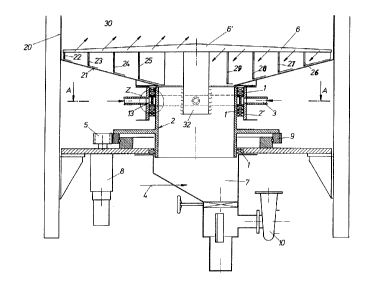
According to Figs. 1 to 3, an agitating arm 6 is disposed in a container 20
with conical bottom 21 in the hottom area as an agitating organ, the arm 6
substantially sweeping the entire container bottom 21 and serving for the
conveyance of the discharge stock, for which purpose it is provided with
conveying scoops 22 to 29. The agitating arm 6 can be composed of several parts
which may for instance form a cross with unequally long arms extending at rightangles to one another. The agitating arm 6 is formed as a deflector projecting
into the interior 30 of the container 20, the basis of the deflector in plan
view (see Fig. 3!) being formed of two symmetrical trapezoids with a common base
line; the deflector has the shape of a wedge facing upwards in elevational view,i.e. it is shallowly ascending towards the middle of the agitating arm, it
extends over the entire length of the agitating arm 6 and prevents the directdropping of the discharge stock into the discharge pipe 2, for which purpose
a cover 5" is further provided in the area of the upper end of the discharge pipe
2, as shown in Fig. 5.
The diluting liquid required for the dilution of the medium to be discharged
passes via feed lines 3 and 3' through inlet orifices 15 and 15' into a
stationary annular channel 14 which is divided into an inner space 14" and aouter space 14', for instance halves 14" and 14', by means of a web 13. The
diluting liquid passes through inlet orifices 15 and 15' into the space 14' and
20~ 8
then through inlet openings 16 disposed in the web 13 , into the space 14" and
from there through openings 17 and 18 into the rotatable element or the pipe 2'
which is sealed against the discharge pipe 2 by means of stuffing boxes 1 (see
Figs. 1 and 8!). The diluting liquid can also be used for the lubrication and
cooling of the stuffing boxes 1. In the rotatable element 2, the liquid is passed
to the agitating arm 6 (Fig. 6!) in the channels 19 formed by uprights 3? andguiding surfaces 33 and feed lines 11. The discharge pipe 2 is fixedly connected
to the agitating arm 6 via said uprights 32. The liquid is passed through orifices
L into the bottom area of the container 20 in order to dilute the medium to be
discharged. The orifices L are evenly distributed over the entire length of theagitating arm 5. Figs. 4a to 49 show that the cross section of the agitating arm
is for instance trapezoidal (Fig. 4a) (preferred), circular (Fig. 4b),
rectangular (Fig. 4c), formed as an isosceles triangle (Fig.4d),as a trapezoid
turned upside down (Fig. 4e), as an equilateral triangle (Fig. 4f) and could bequadrangular (Fig. 49).
Figs. 5a and 5b show exemplary partial representations of an agitating organ
or agitating arm 6 provided with an advantageous embodiment of an obturator A
according to the invention in the area of an orifice L in the agitating organ oragitating arm 6. The obturator A consists of an elongated rubber plate G placed
underneath an equally elongated metal strip M and retained thereby. Metal strip
M and rubber plate G conveniently extend over several orifices L,
advantageously over all the orifices L on one side of the agitating organ or
agitating arm 6. In the area of the individual orifices L, the metal strip M is
provided at C with an approximately triangular cutout, so that when the diluting
liquid exerts a pressure in the interior 34 of the agitating organ or agitating
arm 6 in the area of the orifice L or on the inside I of the rubber plate G which
exceeds the pressure of the medium to be discharged on the outside of the
agitating organ or agitating arm 6 or on the outside AU of the rubber plate G,the orifices L are cleared for the passage of the diluting liquid. If the
interior pressure exceeds the exterior pressure, the rubber plate G is lifted off
in the area of the cutout C from the adjacent orifice or its outer rim, so that
a slot through which the diluting liquid flows into the medium to be dischargedand dilutes it correspondingly is formed on the rim of the rubber plate at D. If,
however, the pressure of the medium to be discharged, i.e. the pressure it
exerts on the rubber plate G (in the area of the cutout C) on its outside AU,dominates, the orifice L is or remains closed by the rubber plate G. A cloggingof the orifices L by the medium to be discharged can thus be prevented.
20501 5~
Other obturators appropriately responding to
the pressure conditions, in particular to the
difference between the pressure of the diluting liquid
and the pressure of the medium to be discharged, both
pressures in the area of the orifices L, could also be
used for the orifices L. Suitable obturators are, for
instance, flap valves, disk valves, non-return (check)
valves and the like.
The uniform distribution of the liquid in
the medium to be discharged is further enhanced by the
fact that the agitating arm 6 is moved simultaneously
with the feeding of the diluting liquid. In the
instant case, the agitating arm 6 is provided with a
deflector 6' directed counter to the feeding direction
of the medium to be discharged. Moreover, as evident
mainly from Fig. 6, a cover 6'' is provided on the side
of the agitating arm so as to complete the covering of
the discharge pipe 2 against the access of the medium
from above and the feeding of the diluting liquid from
the channels 19 into the interior spaces 34 of the
agitating arms 6.
The drive of the agitating arm 6 is effected
by means of a gear motor 8 via a pinion 5, a crown gear
9 and the aforementioned uprights 32 with the discharge
pipe 2.
If the amount of liquid fed to the medium to
be discharged should be insufficient for the required
consistency, additional diluting liquid can be added
via the connection 4 or the diluting space 7. This
connection 4 is mainly used for lower consistencies
(e.g. of about 3 percent), this connection 4 could also
be used for controlling the consistency. The diluted
medium to be discharged is pumped off from the diluting
space 7 by means of a suspension fluid pump or a
monopump 10.
Fig. 8 shows that the feeding of the
treatment liquid, in particular diluting liquid, and
-- 8 --
,. ~
2050 1 5~
the configuration of the stuffing box in this area
could, in a form modified as compared to the
configuration represented in Figs. 1 and 7, provide for
a web 13' abutting the outer wall of the space 14
instead of a web 13 disposed within the space 14, in
particular approximately in the center of space 14.
The vertical cross-section of the web 13 is thus
asymmetrically formed. This space 14''' extends into
the discharge pipe 2 in order to provide sufficient
space for the distribution of the treatment liquid, in
particular the diluting liquid.
The invention can also be applied with
advantage when a different treatment medium instead of
the diluting medium, for instance water, is fed to the
medium to be discharged.
- 8a -
X