Language selection

Search

Patent 2050414 Summary

Third-party information liability

Some of the information on this Web page has been provided by external sources. The Government of Canada is not responsible for the accuracy, reliability or currency of the information supplied by external sources. Users wishing to rely upon this information should consult directly with the source of the information. Content provided by external sources is not subject to official languages, privacy and accessibility requirements.

Claims and Abstract availability

Any discrepancies in the text and image of the Claims and Abstract are due to differing posting times. Text of the Claims and Abstract are posted:

  • At the time the application is open to public inspection;
  • At the time of issue of the patent (grant).
(12) Patent Application: (11) CA 2050414
(54) English Title: DEVICE FOR THE COMBUSTION OF VISCOUS FLUIDS
(54) French Title: DISPOSITIF POUR LA COMBUSTION DE FLUIDES VISQUEUX
Status: Dead
Bibliographic Data
(51) International Patent Classification (IPC):
  • F23K 5/04 (2006.01)
  • F23G 7/00 (2006.01)
  • F23K 5/20 (2006.01)
(72) Inventors :
  • BõKLEP, MAGNE (Norway)
  • SõYSETH, NILS ARVE (Norway)
(73) Owners :
  • NORSK HYDRO A.S. (Norway)
(71) Applicants :
(74) Agent: FETHERSTONHAUGH & CO.
(74) Associate agent:
(45) Issued:
(22) Filed Date: 1991-08-30
(41) Open to Public Inspection: 1992-03-01
Examination requested: 1998-04-16
Availability of licence: N/A
(25) Language of filing: English

Patent Cooperation Treaty (PCT): No

(30) Application Priority Data:
Application No. Country/Territory Date
903811 Norway 1990-08-31

Abstracts

English Abstract


Abstract


Equipment for combustion of viscous
liquids such as tar from gas filters
or the like, comprises a tank (6) with
heating elements (4) a burner unit
(5) and pipe (3) connecting the
burner with the tank.

The pipe protrudes into the tank, and
the end of the pipe in the tank is
connected to a dosage pump (2) of the
displacement type.


Claims

Note: Claims are shown in the official language in which they were submitted.


Claims

1. Equipment for combustion of viscous liquids such as
tar from gas cleaning filters or the like, comprising
a tank (6) with heat elements (4), a burner unit (5),
and pipe (3) connecting the burner with the tank,
c h a r a c t e r i z i n g i n t h a t
the pipe protrudes into the tank and that the end of the
pipe in the tank is connected to a dosage pump (2) of
the displacement type.

2. Equipment according to claim 1,
c h a r a c t e r i z e d i n t h a t
the pipe (3) in close vicinity of the tank is provided
with air flushing means (8).

3. Equipment according to claim 1,
c h a r a c t e r i z e d i n t h a t
the pump (2) is a gear wheel pump.

4. Equipment according to claim 1 and 2,
c h a r a c t e r i z e d i n t h a t
the pump (2) is driven via a shaft (9) of a motor (1)
provided outside the tank.

5. Equipment according to claim 1 and 2,
c h a r a c t e r i z e d i n t h a t
the tank is provided with an inspection cover (10) and
that the pump (2) and pipe (3) is arranged in connection
with the cover (10).

Description

Note: Descriptions are shown in the official language in which they were submitted.


1 2 ~ 3~ t


~he present invention relates to equipment for combustion of
vi5cous fluids such as tar from filters for gas cleaning purposes
or the like, comprising a tank or container with heating
elements, a burner unit, and a pipe for connecting the burner
unit with the tank.

Carbon bodies being used in electrolysis cells for producing
aluminium are prebaked (calcinated) in so-called ring section
furnaces. Due to the strong environmental demands, the gases from
such furnaces are cleaned, and one component which is separated
in this connection is tar. The tar represents a problem with
regard to how it should be deposited as it contains toxins (PAH),
and has otherwise been difficult burn due to its consistency
(viscosity at room temperature and contents of particles).

Atempts have been done to buy equipment for combustion of the
tar, but such equipment has proved not to be useful because of
repeating running problems due to clogged valves and feeding
pumps, and carburization of the combustion nozzle.

In view of the problems with the known equipment, it was decided
to develop specially designed equipment for combustion of filter
tar. An important object with the invention was to provide
combustion equipment which would be reliable, i.e. where the
problems with the clogging and carburization was eliminated and
where the wearing of the equipment was reduced (long life).


Further it was an ob~ect with the învention to provide cheap
equipment ~hich would be simple to maintain.

The invention is characterized in that the pipe which connects
the tank with the burner protrudes into the tank and that the end
of the pipe inside the tank is connected to a dosage pump of the
displacement type. With the here defined solution the pipe is
prevented from being clogged, as no valves or other narrow passes
are provided in the pipe. Further, since the pump is submerged in
the heated liquid in the tank, problems related to congealing of
the liquid in the pump is avoided.

According to a preferred embodiment of the invention as defined
in claim 2, the pipe, close to the tank, is provided with air
evacuation means. Hereby the liquid is prevented from congealing
in the pipe as it can be evacuated with air being blown through
the pipe ~hen the pump is stopped or is out of order.

Claims 3-5 defines preferred embodiments of the driving means and
pump according to the invention. By disposing the motor for the
pump outside the tank as defined in claim 4 and preferably on an
inspection cover as defined in claim 5, simple mounting and
maintenance is achieved together with a more reliable solution.

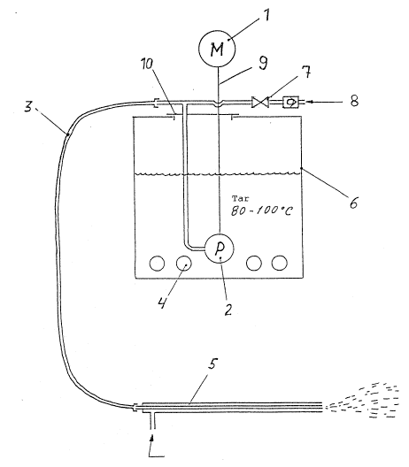
The invention will now be further described by means of examples
and with reference to the drawing which shows a principal sketch
of the equipment for combustion of viscous liquids according to
the invention. The equipment comprises a tank or container 6 with
heating elements 4 controlled by a thermostat, a burner unit 5,
and a pipe 3 for transferring liquid from the tank to the burner
unit. The pipe 3 protrudes into the tank 6, and to the end of the
pipe, slightly above the bottom of the tank, is connected a
dosage pump 2. The part of the pipe protruding into the tank is
preferably made of metal, whereas the pipe outside the tank may
be flexible and made of a suitable rubber composition. The dosage
pump 2 is driven via a shaft 9 by a motor 1 which is disposed
outside the tank. The purpose of providing the motor outside the
tank is to prevent it ~rom being exposed ko the high temperatures

3 2 ~ ~3 ~3 ~
of the liquid in the tank, and besides to avoid problems related
to sealing and mounting of electrical or hydraulical cables or
pipes which otherwise would have to be led into the tank in
connection with the pump drive.

With the here described solucion where the pump is provided in
connection with the pipe insi~e ~he tank, there are no valves or
other potential points on the pipe where clogging will occur.

With regard to the pipe 3, this is in close vicinity of the tank,
provided with air flushing means in the form of an air flushing
pipe ~. By means of a valve 7 on the air flushing pipe 8, the
liquid in the pipe 3 can be evacuated i~ the motor is stopped or
the equipment for other reasons have com0 to a halt. As a further
measurement the pipe 3, may also be provided with a heating
element (not shown), to prevent clogging.

To make it easier to mount and perform maintenance, the pipe 3
and the motor l/dosage pump 2 is disposed in connection with an
inspection cover 10 on top of the tank. Thus the pipe and the
pump can be taken out of the tank by lifting off the cover 10,
and the mounting and maintenance work may be carried out outside
the tank.

As previously mentioned, the tank is provided with heating
elements 4 which are controlled by a thermostat. To prevent heat
losses from the tank and to prevent the liquid from obtaining
high viscosity or congealing in the pipe, both the pipe and tank
is provided with heat insulation. The pump or rather the motor 1
is controlled via a frequency transformer by means of a computer.
Hereby precise dosing is achieved and in turn precise temperature
control for the combustion process.

Even though i~ is initially explained that the equipment
according to the invention is particularly developed to burn
tar from gas filters, it is evident that the equipment can be
used for burning other viscous liquids having high viscosity and
particle content.
Representative Drawing
A single figure which represents the drawing illustrating the invention.
Administrative Status

For a clearer understanding of the status of the application/patent presented on this page, the site Disclaimer , as well as the definitions for Patent , Administrative Status , Maintenance Fee  and Payment History  should be consulted.

Administrative Status

Title Date
Forecasted Issue Date Unavailable
(22) Filed 1991-08-30
(41) Open to Public Inspection 1992-03-01
Examination Requested 1998-04-16
Dead Application 2004-08-04

Abandonment History

Abandonment Date Reason Reinstatement Date
2003-08-04 R30(2) - Failure to Respond
2003-09-02 FAILURE TO PAY APPLICATION MAINTENANCE FEE

Payment History

Fee Type Anniversary Year Due Date Amount Paid Paid Date
Application Fee $0.00 1991-08-30
Registration of a document - section 124 $0.00 1992-06-02
Maintenance Fee - Application - New Act 2 1993-08-30 $100.00 1993-07-15
Maintenance Fee - Application - New Act 3 1994-08-30 $100.00 1994-07-20
Maintenance Fee - Application - New Act 4 1995-08-30 $100.00 1995-07-28
Maintenance Fee - Application - New Act 5 1996-08-30 $150.00 1996-07-15
Maintenance Fee - Application - New Act 6 1997-09-02 $150.00 1997-07-16
Request for Examination $400.00 1998-04-16
Maintenance Fee - Application - New Act 7 1998-08-31 $150.00 1998-07-21
Maintenance Fee - Application - New Act 8 1999-08-30 $150.00 1999-07-15
Maintenance Fee - Application - New Act 9 2000-08-30 $150.00 2000-07-18
Maintenance Fee - Application - New Act 10 2001-08-30 $200.00 2001-07-04
Maintenance Fee - Application - New Act 11 2002-08-30 $200.00 2002-07-08
Owners on Record

Note: Records showing the ownership history in alphabetical order.

Current Owners on Record
NORSK HYDRO A.S.
Past Owners on Record
BõKLEP, MAGNE
SõYSETH, NILS ARVE
Past Owners that do not appear in the "Owners on Record" listing will appear in other documentation within the application.
Documents

To view selected files, please enter reCAPTCHA code :


To view images, click a link in the Document Description column. To download the documents, select one or more checkboxes in the first column and then click the "Download Selected in PDF format (Zip Archive)" or the "Download Selected as Single PDF" button.

List of published and non-published patent-specific documents on the CPD .

If you have any difficulty accessing content, you can call the Client Service Centre at 1-866-997-1936 or send them an e-mail at CIPO Client Service Centre.


Document
Description 
Date
(yyyy-mm-dd) 
Number of pages   Size of Image (KB) 
Representative Drawing 1999-07-06 1 11
Cover Page 1993-11-03 1 15
Abstract 1993-11-03 1 12
Claims 1993-11-03 1 28
Drawings 1993-11-03 1 16
Description 1993-11-03 3 144
Description 2001-12-28 4 168
Claims 2001-12-28 3 79
Claims 2002-08-30 3 79
Description 2002-08-30 4 168
Assignment 1991-08-30 9 338
Prosecution-Amendment 1998-04-16 1 47
Prosecution-Amendment 1998-06-05 4 130
Prosecution-Amendment 2001-07-03 3 97
Prosecution-Amendment 2001-12-28 7 237
Prosecution-Amendment 2002-03-01 3 142
Prosecution-Amendment 2002-08-30 9 366
Prosecution-Amendment 2003-02-04 3 138
Fees 1996-07-15 1 38
Fees 1995-07-28 1 42
Fees 1994-07-20 1 49
Fees 1993-07-15 1 32