Note: Descriptions are shown in the official language in which they were submitted.
2 ~
-
-- 1 --
~~T~OD ~ App~Tr~ FS:~R ~ A
~ Y ~ARYING 8EclI I~C~i~B~
Fiel~ ~ th0 :Cn~Q~tio~
The invention pert:ains to ~;ecurity ~;y tems
useabl~ to authenticate documents or other ob~ec:t~. Mc>re
particularly, the invention pertain~3 to an apparatus and
a method fox ar~iIicially enhancing an existing random
characteristic of a medium for E;ecurity purpose~:.
~lcqrou;~dl o~ th~ v~l3ntio~ ;
Various typ~!!8 of ~ecurity ~ystems usable to
authenticate doc:uments or oth2r ob~eots are lcn~wn. For
example, U.~;. Patent No. 4,506,98B to Copella entitled
"Object Veri~ication 5ystem ~nd Method", assigned to the
assignee o~ the present invention and incorpora'ced herein
lS by referenc2, discloses a particular ~oxm ~f a security
~ystem which utilizes chara~teristics o~ ~paced-apart
magnetic regions. Previous~y issued ~.S~ Patent ~o.
4,837,426 to Pease et al. entitled 'IObject Veri~i~ation
Apparatus and Method" describe~ a particular form o~ a
magnetic security ~ystem which is usable with a
continuously extending magnet~c region.
Other ~y~te~s are known whi~h utilize a randomly
varyin~ translucency characteristic of paper and the like.
Security ~ystems are al~o possible where another randomly
varying characteristic, ~uch a~ print variations, o~ an
ob~ect or 3 document are ~vailabls ~or U5~
Prior systems hav~ often util~ed the randomly
varying ch3racteristias a~ they existed in the document
or the ob~ect. ~hile ~u~h syst~ms are us~ul, th~re are
t~m~s when it would be desirable to physically 2nhance or
~xaggerate the random v~riation at ~he ~ime whe~ the
randomly va~ying characteristic i8 ~r~ated.
~he abov~: noted Pea~a et al. patent ~akes
re~erence to enhancing random magnet~c regio~ by:
underprinting or overpr~nting wi~h magne~ic ~nk in the
2 ~
vicinity o~ the magnetic security regionO The same patent
also refers to embossing, ~cratching or o-ther methods of
removable of a portion of the magnetic material to create
a more readily detectable characteristic.
Beyond creating an e~aggerated or an enhanced
~ecurity region by physically altering a portion of the
region, it would be desirable to be able to do so in such
a way so as to make duplication or copying of the enhanced
regions difficult or impossible. Further, it would be
desirable ~o be able ~o create an enhanced ~tructure using
a method which does not appreciably add to the cost of
producing what might otherwise be a very inexpensive
document.
um~ary o~ the In~entio~
An apparatus for creating an enhanced random
security characteristic in a region of a medium includes
a 6ignal modulator. A random electrical output ~rom the
modulator is coupled to an output device~
~he output device can generate one of a
plurality o~ different ~ypes o~ physical outputs depending
on the medium to be enhanced.
I~ the medium i~ magnetic, the output device can
be a magnetic write head. I~ the medium is optical, the
output device can be a source of light energy such as a
laser. X~ the medium is thermally sensitive, the outpu~
device can be a source o~ thermal enerqy.
The modulat~r can receive a randomly varying
input signal to be modulated. The modulating signal can
be a second randomly varying siqnal.
3Q The result of using the present apparatus will
be an enhanced, permanent, randomly varying characteristic
in or on the region of the medium, to be used for security
purps:~;es,. Because the region has been enhanced by means
oi one or more randomly varying signal~, the process is
,
2 ~
-
very di~icult if not impossible to ~mulatP. Further, no
two regions will be enhanced in the same way.
A method of enhancing includes the steps of~
providing a medium having a randomly varying
characteristic;
generating a random condition; and
modi~ying the medium in response to the random
condition to create an enhanced randomly varying
characteristic.
0 Numerous other advantages and features of the
present invention will become readily apparent ~rom the
following detailed description of the invention and the
embodiments thereof, from the claims and from the
accompanying drawings in which the detail~ o~ the
invention are ~ully and completely disclo~ed as a part of
this specification.
risf De oriPtion of th~ ~rax~a~
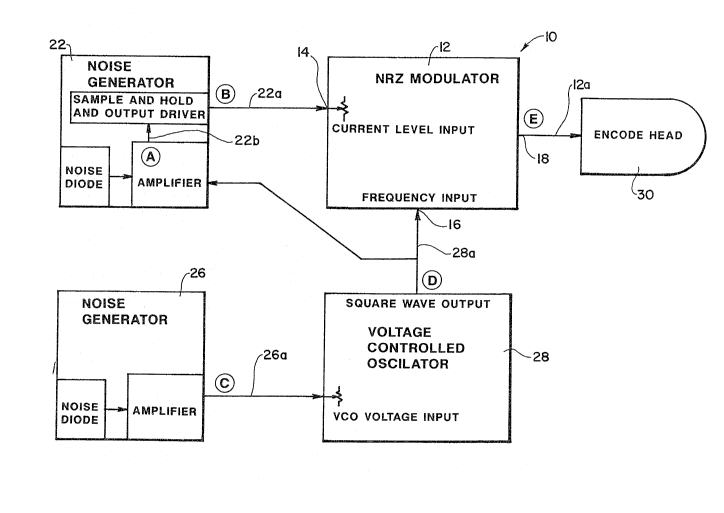
Figure 1 is a block diagram schematic
illustrating an electrical system for enhancing a magnetic
security region in accordance with the present invention;
Fiqure 2 is a graph illustrating plots of
various electrical signals5 from the block diagram of
Figure 1, as a function of time;
Figures 3A-3C il~ustrate schematically, in
2S various views, a representation of an enhanced magnetic
security region;
Figures 4A-4C illustrate schematically, in
various views, an alternate enhanced magnetia security
~ region; and
Figure 5 is an overall schematic diagram o a
system ~or enhancing the rand~ magnetic characteristic
o~ a magnetic ~ecurity region in accor~ance with the
present in~ention.
2 ~
- 4 -
etaile~ De~ori~;o~ of_the Pre~erre~_E~di~tY
While this invention is susceptible o~
embodiment in many different forms, ther~ are ~hown in the
drawiny and will be described herein in detail specific
embodiments thereof with the understanding that the
present disclosure is to be considered as an
exemplification o~ khe principles o~ the invention and is
not intended to limit the in~ention to the specific
embodiment illustrated.
Figure 1 illustrates a block diagram schematic
of an electrical system 10 usable to alter the
distribution of magnetic particles in a fluid magnetic
stripe. For example, magnetic 6tripes are o~ten created
on documents by depositing a slurry on a moving underlying
medium. The medium can be a card stock or a plastic
material from which individual documents can be created.
The slurry, until subsequently being hardened
contains numerous, suspended, movable magnetiG particles.
When hardened, a permanent magnetic stripe with fixed
magnetic characteristics ~s formed.
The ele~trical system 10 of Figure 1 can be used
to modify selected portions o~ the magnetic slurry before
the slurry is hardened. As a reslllt, the physical
distribution of the magnetic particles in the slurry can
be substantially altered, in a random fashion, using the
system 10,
The system 10 ~ncludes an NRZ (non-return to
zero) modulator 1~. The modulator ~2 has an input port
14 for an electrical signal to be modula~ed and an input
port 16 ~or a modulating signal.
The ~odulator 12 also includes a modulated
output port 18. A noise generator 22 which generat~s an
ap~roximation to white noise, for exampler can be used to
proYide an electrical signal with a randomly varying
amplitude~ ~he randomly varying eleo~rical output ~rom
2~5,~a2~
the generator 22, on a line 22a can be coupled to the
input port ~4 of the modulator 12.
A second noise generator 26 can be used to
create a randomly varying amplitude electrical signal on
S a line Z6a. The electrical signal on the line 26~ can be
used as an input to a voltage controlled oscillator 28~
Output fro~ the voltage controlled oscillator on a line
28a various in frequency in response to the amplitude ~f
the randomly varying signal on line 26a.
Output from the voltage controlled oscillator
28 is coupled via the line 28a to the modulation input
port 16 of the modulator 120 The line 28a is also coupled
as an input to the first generaltor 22 so as to synchroniz~
the signal variation~ on the line 22a with the ~requency
variations on the line 28a.
()utput from the modulator at the port 18 is
coupled to a magnetic wri~e head 30 via a line 12a.
Output from the magnetic write head 30, an elecltro-
magneti~ field, can be used to displace the magnetic
~0 particles in an adjacent moving magnetic slurry.
Figure 2 is a graph illus~rating~various wave-
forms of the circuit of P~igure 1 a a function of time.
The top most waveform, a constant amplitude signal o~
variable ~requency corresponds to the output o~ the
2S voltage control oscillator ~8 on the line 28a. The second
wave form in the graph of Figure 2 c~rresponds to a
randomly varying amplitude signal generated by noise
generator 2~ which fo~ms ~he input on the line 26a to th~
voltage control osoillator 28.
30 : The ~hird waveform in Figure 2 represents a
randomly ~arying amplitude electrical signal generated on
a line 22b which i~ internal to the nois~ generator 22.
The fourth electrical signal in th~ graph o~ Figure 2 i5
the ~lectrical signal on the line ~Za with a randomly
varying ampli~ude, bas~d on the eleGtrical sig~al on line
2 ~7
- 6 -
22b, synchronized in frequency with the output on the line
28a of the voltage controlled oscillat.or 28.
The bottom signal o~ the graph o~ ~igure 2 is
a representation o~ the modulated out'put ~urrent on the
S line 12a from the modulator 12 whi~h is the driving
current for the write head 30. Thls electro-magnetic
signals generated by the write head 30J responsive to the
current on the line 12a, alter the spatial distri~ution;
in a random fashion, of the ~agnetic particles in an
adjacent magnetic slurry. This alteration results in an
enhanced random magnetic security characteristi~.
Figures 3A-3C represent diagrammatically the
altered densities of the magnetic ~lurry which can be
achieved us~ng the sy~te~ 10.
For example, with respect to Figure 3A, a
verifiable document or card 40 is ~ormed with a support
medium 42 which could be plastic or card stock. Carried
on the medium 42 is a previou~ly deposited and hardened
magnetic stripe 44. Prior to hardening the~ magneti~
~tripe 44, the fluid slurry was subjected to
electromagnetic fields generated by the system 10 using
the write head 30.
Figure 3B, an enlarged sectional view,
illustrates variations in the density of the particles o~
the magnetic stripe 44 which have been created by means
of the system lOo For example, region 50a represents
pictorially a higher density concentration of magnetic
particles than is present in an adjacent region o~ a
: different size o~ 50b.
Adjacent to the lower density region 50b is yet
another region of a diffe~ent density and length ~Oc.
Thus, ~s illustrated in Pigure 3B, th~ ma~netic stripe 40,
in it~ hardened state, incIudes a plurali~y of spaced
apart 2nhanced magnetic reyions having differing]nagnetic
oh~raoteristic~ and different ~ize~.
. .
~.~
.
2~5~
Figur~ 3C is an enlargement o~ a portion of the
magnetic stripe 44 a~ ~een in a top elevational view.
The enlarged detail illustrated in Fi.gure 3C corresponds
to the ectional ~iew of Figure 3B.
The region 44 illustrated in Figure 3C i~ formed
with three distinct sections. Section 44a and section 44b
represent regions of the magnetic slurry which prior to
hardening were not subjected to sufficient strength of the
electromagnetic field ~rom the write head 30 o~ the system
10 to disturb the random distribution of the magnetic
particles so as to create an enhanced random magnetic
region.
The portion 44c, on the other hand,
corresponding to the seational view o~ Figure 3B,
lS represent~ the part o~ the magnetic stripe 44 which has
been subjected to the enhancing electromagnetic field o~
the write head 3~. The shadings and various colors
illustrated:in the region 44c are indicative o~ varying
densiti2s of magnetic particle~ present in the hardened
stripe 44.
The region 44 thus repre~ents a permanent,
enhanced, randomly varying magnetic characteristic
embedded within the magnetic ~tripe 44. This
characteristic c~n be read and compared to a previously
stored representation ~hereo~ as disclosed and taught in
ths previou~ly issued Pease et al. and Copella patents.
Figures 4A-4C illustrate the verifiable document
42 with a dif~erent, enhanced, random chaxacteristic. The
~a~netic stripe 44 has been modified across its entixe
width by a system such as the:sy6tem 10. As illustrated
in Figure ~C, the portion 4~c which includas ~he enhanced
randomly va~ying magneti~ charac~eristic extends for the
entire width of the stripe 44.
Figur 5 illu~trate~ a system 60 which
incorporates the ~ystem 10 coupled to the read head 30 in
conjunztion with a slurry extruding dev:ice. As illustrate
in Figure 5, the system 60 includes a medium 62 movable
perhaps by roller~ or the like past a ~agnetic stripe
extrusion head 64. As the m@dium 62 moves in a direction
62a under the extrusion head 64, a magnetic stripe 6~ is
extruded in a fluid co~dition.
As the medium 62 continues to movP in the
diraction 62a, the deposited stripe 66 moves past the
adjacent write head 30 which i~ ~eing ~ri~n by the sys~em
10. As the stripe 66 moves past the write head 30, the
magnetic p~rticles therein are displaced as indicated
schemati~ally in Figures 3c and 4c, depending on the width
of the electromagnetic ~ield and the strength thereof
relative to the width o~ the stripe 66. Subse~uently, the
enhanced magnetic ~lurry, still in a liguid state, passes
through a dryer 66 whi~h hardens the sl~rry and fxeezes
the displa~ed magnetic particles permanently in place.
When the medium wi~h the hardened magnetic
stripe 66 exits the dryer 70, the medium can be cut to
form discrete cards or documents such as the document 42.
As a result of cutting and æhaping the documant 42, the
portion o~ the magnetic stripe 44 carxied on the document
will also carry with it the permanently enhanced magneti~
region that is illustrated by the region 44c.
While the present method and apparatus have been
disclosed and described in terms o~ ~ magnetically based
security system, ik will ~e understood that the
characteristics of the particular enhanceable medium are
r,ot a limitation of the present inventionO For examplP,
alternately, instead of a magnetic medium, an optical
medium can be used~ Instead of a write head, such as the
writ~ head 30, a modulatable light or laser can be used
to expose regions of ~he optical medium.
A ~odulated laser can be used as an output
device ~or removing or burning off portions o~ the ~edium
2~
g .,
whose rharacteristic is to ~e enhanced. Similarly, a
modulatable thermal element can be used to heat portions
of a ~ecurity medium which are healt sensitive thereby
producing a thermally induced variation in a randomly
varying security characteristic~ All o~ the 3b~ve method
of enhancing a random security characteristic can be used
alone or in c~mbination with other security techniques~
It will be understood thak other variations of
randomly variable security characteristic, when modified
as disclosed herein, come within the scope and bounds of
the present invention.
From the ~oregoing, i~ will be observed that
numerous variations and modifications may be effected
without departing ~rom the spirit and scope o~ the novel
concept of the invention. It is to be understood that no
limitation with respect to the specific apparatus
illustrated herein is intended or should be inferred. It
is, of course, intended to cover by the appended claims
all such modifications as fall within the scope of the
claims.