Note: Descriptions are shown in the official language in which they were submitted.
63~
The present invention relates to a vertical screw
cutter/mixer with a screw supported solely at its base.
5 BACKGROllND OF T~{E I~lVENTION
There are a number of vertical screw mixers in which
the screw is supported solely at its base. However, this
type of screw has never been successfully used in a cutting
application, their use is presently restricted to~a mixing
function; mixing material which is substantially precut.
In theory, a vertical screw supported solely at its base
presents a number of potential advantages in a cutting
application. There is no stationary top support against
which material can become jammed. This jamming occurs with
15 top supported screws when material gets wedged between the
top support and the flighting of the screw. It causes a
bending of the top support and damage to the drive
mechanism. In view of the potential for jamming, vertical
screw cutterlmixers having top supports must be engineered
to withstand the stresses which result from jamming. This
results in increased costs of manufacture. In addition,
the machines have increased weight which can be a factor in
mobile applications.
A recent example of an attempt to use a vertical screw
supported solely at its base in a cutting application is
illustrated in United States patent 5, 020/ 918 which issued
to To Faccia in 1991. The Faccia patent can be used to
illustrate some of the problems involved. The Faccia
patent discloses a stand alone screw having a plurality of
short blades extendin~ upwardly from the top of the shaft
of the screw. In theory, the blades are intended to shred
material. In practise, a bale of material merely becomes
impaled on the blades and rotate at substantially the same
speed as the screw. The convolutions of the flight of the
screw serve to move material upward, therefore, a bale of
material resting on the flighting of the screw is
continually lifted and maintains a static position at the
top o~ the container.
~0~6i30
SUMM~RY OF THE INVE~TION
What is required is a vertical screw cutter/mixer with
a screw supported solely at its base which is capable of
cutting large bales of material.
According to the present invention there is provided
an improvement in a vertical screw cutter/mixer consisting
of an inverted generally conical container and a vertical
screw. The vertical screw is rotatably mounted within the
container solely at its base. The improvement is comprised
of a combination of elements. A spiral flight is provided
on the screw consisting of a plurality of convolutions
describing a truncated conical shape. Means is provided
for mounting a plurality of blades to the screw such that
they extend upwardly past the apex of the shaft of the
screw. At least one of the blades is positioned adjacent
a peripheral edge of an upper convolution of! the flight
such that a circular path is described by the peripheral
blade which is substantially the same diameter as the upper
convolution of the flight. Impaling fingers are positioned
adjacent to the top of the container and extend inwardly.
The impaling fingers are in substantially horizontal
alignment with the upwardly extending blades. The
impaling fingers are movable between an extended position
and a retracted position. In the extended position the
fingers impede the speed of rotation of the bale to less
than the speed of rotation of the screw whereupon the
blades tear chunks of material from the bale. In the
retracted position the fingers release the bale whereupon
the bale descends upon the screw.
With the vertical screw cutter/mixer as described is
suited for cutting 2000 pound round bales of hay in
agricultural applications and similar sizes of bales in
garbage processing applications. The impaling fingers
impede the rotation of the bale to permit an effective
cutting action by the upwardly extending blades. Having at
least one of the blades positioned adjacent t,he peripheral
edge of the upper flight in combination with the truncated
2~S~6~
conical shape of the ver-tical screw, ensures that the
blades remove enough material from the bale to permit the
bale to descend further into the container without becoming
"hung up" on the upper flight. The impaling fingers are
alternately extended and retracted as the bale is dispersed
into the container. In the extended position the impaling
fingers hold the bale to resist rotational and upward
movement to allow further penetration of the upper blades.
In the retracted position the weight of the bale causes
the bale to descend further into the container past the
upper convolu-tion of the ~runcated conical screw.
BRIEF DESCRIPTION OF THE D~AWINGS
These and other features of the invention will become
more apparent from the following description in which
reference is made to the appended drawings, wherein:
~IGURE 1 is a section view of a vertical screw
cutter/mixer constructed in accordance with the teachings
of the present invention.
~IGURE 2 is top plan view of the vertical screw
cutter/mixer illustrated,in FIGURE 1.
~IGURE 3 is a section view of an alternate embodiment
vertical screw cutter/mixer constructed in accordance with
the teachings of the present invention.
FIGURE 4 is top plan view of the alternate embodiment
of the vertical screw cutter/mixer illustrated in FIGURE 3O
~ETAILED DE5CRIPTIO~ OF T~E PREFERRED ~M~ODI~E~T
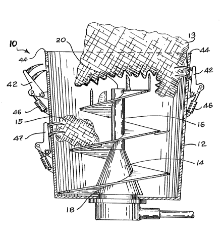
The preferred embodiment, a vertical screw
cutter/mixer generally identified by reference numeral 10,
will now be described with reference to FIGURE~ ~ and 2.
The present invention is an improvement in vertical
screw cutter/mixer 10. Those elements of vertical screw
cutter/mixer 10 which are known in the prior art are an
inverted conical container 12 and vertical screw 14.
Vertical screw 14 has a shaft 16 with a base 18 and an apex
20. Vertical screw 14 is supported solely at base 18 and
is rotatably mounted within container 12. The means for
4 ~5~
rotatably mounting base 18 does not form part of this
invention and will not be further described.
The improvement lies in modifications which have been
made to vertical screw cutter/mixer 10 to enable vertical
screw cutter/mixer 10 to accommodate large bales of
material 13. Bales of material 13 are encountered in
agricultural applications and garbage processing
applications. For example, cattle operations cut 2000
pound round bales of hay and mix the hay with other
agricultural produce to provide a cattle feed that is
properly balanced in nutrients. In order to function in
combination with other elements which will be hereinafter
further described screw 14 must take a particular form.
Screw 14 must have spiral flight 22 which generally
describes a truncated conical shape. Flight 22 has a
plurality of convolutions; three convolutions are
illustrated in FI&URE 1, which for the purpose of this
description shall be described as an upper convolution 24,
and lower convolutions 26 and 28. Upper convolution 24 is
positioned immediately adjacent apex 20 of shaft 16 of
screw 14. Two types of blades are secured to screw 14.
Blades 30 extend radially from flight 22. Blades 32, 34,
36, and 38 extend upwardly from upper convolution 24 past
apex 20. As is illustrated in FIGU~E 2, each of blades 32,
34, 36, and 38 is positioned a different radius from shaft
16. The result is that blades 32, 34, 36, and 38 describe
a series of concentric circles. It should be noted that
blade 38 is positioned adjacent a peripheral edge 40 of
upper convolution 24 of flight 22, such that the circular
path described by blade 38 is substantially the same
diameter as upper convoiution 24. Impaling fingers 42 are
positioned adjacent to a top edge 44 of container 12 and
extend inwardly. Impaling fingers 42 are in substantially
horizontal alignment with the blades so as to cooperate
with them. Impaling fingers 42 are movable between an
extended position and a retracted position by means of
hydraulic actuators 46. A further set of impaling fingers
~5~6~(~
47 are positioned in substantial horizon-tal alignment with
lower convolution 26. Hydraulic actuators 46 and
associated controls are known in the art, do not form part
of the invention and will therefore not be further
described.
The use and operation of-the improvements in vertical
screw cutter/mixer 10 will now be described in relation to
FI~UR~S 1 and 2. In the agricultural example previously
referred to, a 2~00 pound round bale 13 is placed upon top
edge 44 of container 12 by means of a tractor with a front
end loader (not shown). Initially, bale 13 become~ impaled
upon blades 32, 34, 36, and 38 and is held up by apex 20 o~
shaft 16 and upper convolution 24 of flight 22. In this
position bale 13 rotates at substantially the same speed as
shaft 16, and is continually being lifted upwards by flight
22. Impaling fingers 42 are then moved to an extended
position by means of hydraulic actuators 46. In the
extended position impaling fingers 42 impede the speed o~
rotation of the bale to less than the speed of rotation of
screw 14 whereupon blades 32, 34, 36, and 38 tear chunks 15
out of bale 13. By virtue of thè positioning of blade 38
on the peripheral edge 40 of upper convolution 24 of flight
22, sufficient material is removed from bale 13 to provide
clearance for upper convolution 22. Impaling fingers 42
are then moved to a retracted position by means of
h~draulic actuators 46. In the retracted position impaling
fingers 42 release bale 13 whereupon bale 13 descends into
container 12 until its descend is impeded by upper
convolution 22 of screw 14. As previousl~ mentioned, the
truncated conical shape of screw 14 is of importance in
leaving sufficient room for bale 13 to descend. Impaling
fingers 42 are alternatively moved between an e~tended
position and a retracted position until bale 13 has
descended pa~t upper convolution of screw 14. Once bale 13
descends ~ar enough into container 12, blades 30 are also
able to contr:ibute to the cutting of bale 13. In order to
prevent chunks 15 from circulating wi-thout being cut, lower
impaling fingers 47 are provided.
The alternate embodiment, a vertical screw
cutter/mixer generally identified by reference numeral 100,
will now be described with reference to F~G~ES 3 and 4.
The components of vertical screw cutter/mixer 100 are
identical in most respects to the components of vertical
screw cutter/mixer 10 previously described. For that
reason only the differences will be further described.
Vertical screw cutter/mixer 100 illustrates an alternate
blade mounting means. In vertical screw cutter/mi~er 10
the means of mounting blades 32, 34, 36, and 38 was to
secure them to upper convolution 24 of spiral flight 22.
With vertical screw cutter/mixer 100 the means for mounting
a plurality of blades to screw 14 is a blade support 102.
Referring to FIGURES 3 and 4, a plurality of blades 104,
105, 106, and 107 are secured to blade support 102. Blade
support 102 is, in turn, secured transversely to shaft 16
adjacent apex 20 of screw 14. The blades are spaced
radially from shaft 16 at intervals along blade support
102. Blade support 102 rotates with shaft 16 of screw 14,
and when it does so the path of the blades describè a
series o~ concentric circles. Blade 104 is positioned
adjacent to peripheral edge 40 of upper convolution 24 of
spiral flight 22. By virtue of the positioning of blade
104 adjacent peripheral edge 40 of upper convolution 24 of
flight 22, a sufficient portion of the bale is torn away to
prevent the bale from becoming hung up on upper convolution
24 of flight 22.
It will be apparent to one skilled in ths art that
modifications may be made to the illustrated embodiment
without departing from the spirit and scope of the
invention.