Note: Descriptions are shown in the official language in which they were submitted.
2~7~
--1--
APPARATUS FOR CONTINUOUSLY lMONlTORlNG
A PLURALITY OF CEI~MICAL ANALYTES
l~ROUGH A SINGLE OPl~iCAL FIBER AND METHOD OF MAKING
Technical Area
S This invention relates to fiber-optic sensors suitable for mon;toring chemical
analyte concentrations and to a method of making such sensors.
Background of the Invention
In recent years1 fiber-optic chemical sensors, sometimes called optrodes9
have been developed to detect the presence and rnonitor the concentration of
various an~lytes, including oxygen, carbon dio~ide, and pH, in liquids and in
gases. Such sensors are based on the recogni~ed phenomenon that the absorbance,
and in some cases, the lum;nescence, phosphorescence, or fluorescence of certainindicator molecules are specifically perturbed in the presence of specific analyte
molecules. The perturbation of the luminescence and/or absorbance profile can bedetected by monitoring radiation that is absorbed, reflected, or emitted by the
indicator molecule in the presence OI a specific analyte.
Fiber-optic probes relying upon these characteristics position the
analyte-sensitive indicator molecule in a light path at a desired measurement
site. Typically, the optical fiber transmits electromagnetic radiation from a light
source to the indicator molecule, and the reflectance from or absorption of light
by the indicator molecule gives an indication of the gaseous or ionic concentration
of the analyte. Alternatively, for monitoring other analytes such as 2~ the
optical fiber transmits electromagnetic radiation to the indicator molecule,
exciting it into phosphorescence, and the level and/or duration of phosphorescence
by the indicator molecule serves as an inclication of the concentration of that gas
in the surrounding fluid. In the prior art probes, the indicator molecules are
typically disposed in a sealed chamber at the distal end Oe the optical fiber, and
the chamber walls are permeable to the analytes of interest.
'
-2- ~ 7 3 8
One problem with the known sensing systems of the type described is that
the optical fiber and chamber attached to the end of the probe are prone to
physical damage. The optical fibers with attached sensing chambers are delicate
because they are disposed as an external appe~dage at the end of the probe,
extending distally beyond a catheter through which the probe is positioned inside a
patient's circulatory system. Any mishandling of the catheter can easily result in
damage to the delicate sensor chamber.
An additional problem with the known sensing systems described above is
that the structure of the chambers and probe configuration often encourage the
formation of blood clots, or thrombi. Typically the sensors of the prior art
contain discrete optical fibers for each blood gas parameter such as 2~ pH, andCO2. This multiplicity of fibers adds to the diameter of the complete probe and
provides interfiber crevices that encourage thrombi formati~n. Furthermore9 the
complexity and difficulty of manufacturing multï-fiber probes is well known, dueto the small diameters of the fibers and requirements for their arrangement.
Even though R bundled optical fiber probe for sensing a plurality of analytes may
have a remarkably small overall cross section, its size can still preclude its use in
neonatal or pediatric applications in which the patient's veins or arteries are too
small in diameter for insertion of the sensor assembly. Thus, prior art
multi-analyte sensors fail to effectively deal with several problems.
Summary of the Invention
In accordance with the present invention, a probe for monitoring a plurality
of chemical parameters includes an optical fiber having a longitudinal axis along
which light signals at a plurality of wavelengths are propagated bidirectionally.
An optical sensor is attached adjacent to a distal end of the optical fiber and
comprises a first analyte indicator. Light signals of a first wavelength are
absorbed by the f irst analyte indicator to an extent dependent upon the
concentration of a first analyte present. A second polymer matrix msterial
containing a second analyte indicator is disposed adjacent to the distal end of the
optical fiber and adjacent to the optical sensor. Light signals of a second
wavelength that are transmitted to the distal end of the optiaal fiber excite the
second analyte indicator to emit light. A decay time for the li~ht emission varies
in response to a concentration of the second analyte.
In one ernbodiment of the probe, the first analyte indicator is sensitive to
carbon dioxide concentration. In a second embodiment, the first analyte indicator
is sensitive to a pH level. In both embodiments, the second analyte indicator issensitive to oxygen concentration. The optical sensor can be attached to the
$
distal end of the optical fiber with a thin coat of the polymer matrix materisl that
is proYided with the second analyte indicator. In addition, the sensor pellet and
the distal end of the optical fiber can be covered with a coating comprising thepolymer matrix material and the second analyte indicator.
S Preferably, the optical sensor ~omprises a pellet attached to a transverse
surface oî the optical fiber at its distal end. In one form of the probe, the pellet
covers only a portion of the transverse surface and the polymer matrix material
provided with the second analyte indicator encloses the pellet, the transverse
surface, and the distal end of the optical fiber.
In another form of the probe, the polymer matrix material, including the
second analyte indicator, comprises a layer that is interposed between the optical
sensor and the distal end of the optical fiber. Where the first analyte is ionized in
water, a hydrophilic coating is applied over the layer of the polymer matrix
material that is provided with the second analyte indicator, and over the optical
sensor. However, where the first analyte is a gaseous substance, a hydrophobic
coating is applied over the layer of the polymer matrix material containing the
second analyte indicator, and over the optical sensor. Pref erably, the second
analyte indicator comprises a porphyrin compound and is substantially unaffectedby light signals at the first wavelength.
. ~.
A method for making a chemical sensor comprises a further aspect of this
invention. In accordance with the method, a first polyrner matrix is mounted on
at least a portion of a distal end of an optical fiber so that light propagatingthrough the optical fiber passes into the first polymer matrix. The first polymer
matrix contains a first indicator molecule that absorbs light of a first wavelength
z5 in proportion to the concentration of a first analyte. A thin film of
light-reflective material is applied adjacent to the first polymer matrix, such that
light of the first wavelength propagated distally along the optical fiber and
through the first polymer matrix is reflected by the thin film of light-reflective
material, back towards a proximal end of the optical fiber. A second polymer
matrix is also applied to the distal end of the optical fiber and contains a second
molecule that emits light when excited by light of a second wavelength to an
extent that is proportional to the concentration of a second analyte disposed
around the sensor.
" .~
, Where the first analyte is carbon dioxide, the method further comprises the
35 step of coating the first polymer matrix and the c~istal end of the optical fiber
with a hydrophobic material. Where the first analyte comprises hydrogen ions, the
method further comprises the step of coating the first polymer matrix and the
distal end of the optical fiber with a hydrophilic material.
`
4 ~ 7
In one form of the method, the second polymer matrix is applied prior to the
step of coating the first polymer matrix such that the second polymer matrix is
substantially interposed between the distal end of the optical fiber and the first
polymer matrix. The first polymer matrix can be applied over only a portion of
S the trans~/erse area of the distal end of the optical ~iber such that light of the
second wavelength is incident upon the second polymer matrix through a
remainder of the transsterse area of the distal end.
Brief Description of the Drawin~s
The advanta~es of this invention will become more readily apparent by
reference to the following Detailed Description of the Preferred Embodiments, inconjunction with the accompanying drawings wherein:
FIGURE 1 is an isometric view o~ a first embodiment of a sensor ~or
determining CO2 and 2 concentration in accord with the present invention;
FIGURE 2 is a transverse view illustrating the distal end of the sensor of
FIGURE 1;
FIGURE 3 is a longitudinal view of a second embodiment of the sensor shown
in FIGURES 1 and 2;
FIGURE ~ is a longitudinal view of a third embodiment of the sensor shown
in FIGURES 1-3;
FIGURE 5 is a longitudinal view of a fourth embodiment of the sensor used
to measure pH and oxygen concentration;
FlGURE 6 is a longitudinal view of a fifth embodiment of the sensor, also for
use in measuring pH and oxygen concentration; and
FIGURE 7 is a block diagram of a system for use with any of the
embodiments of the sensor to measure oxygen snd either carbon dioxide
concentration or pH.
Detailed Description of the_ef red Embodiments
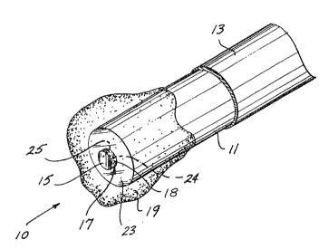
A first preferred ernbodiment of the fiber-optic sensor is shown in
FIGURES l and 2, generally at reference numeral 10. Sensor 10 includes an
optical fiber 11 encased within a polyimide sheath 13, which covers the entire
optical fiber ll, except Eor an exposed portion that extends beyond polyimide
sheath 13. In this embodiment, the portion of the optical fiber that extends
beyond polyimide sheath 13 is preferably about 600 micrometers in length. The
distal end of optical fiber 11 has a generally planar circular surface 23, which is
cleaved substantially perpendicular to the longitudinal axis of optical fiber 11.
Bonded to circular surface 23 of optical fiber ll is a cylindrical carbon dioxide
(CO2) pellet 17, having a first circular surface 24 disposed directly adjacent to
and substantially centered on circular surface 23 of optical fiber 11.
5 2~ 7c~j~
Disposed on a second circular face 25 of the CO2 pellet is a thin film of
reflective material 15 (preferably comprising gold foil), which is provided to
reflect a light signal propagated through optical fiber 11. Reflective material 15
is substantially concentric with second circular surface 25. It can be appreciated
that refleetive material 15 and circular surface 25 o~ optieal fiber 11 mu~t be
substantially perpendicular to the longitudinal axis of optical fiber 11 to reflect
light transmitted through optical fiber 11 and incident on reflective material 15
back into and along the longitudinal axis of the optical fiber. C02 pellet 17
preferably has a longitudinal thickness on the order of 50 micrometers. C02
pellet 17 comprises a CO2 analyte indicator moleeule codissolved within a
polymer matrix, producing a C02 sensitive material 18 that absorbs light of a
predefined wavelength to an extent that depends on the concentration of CO2
around C02 pellet 1~. C02 pellet 17 is attached to the distal end o~ optical
fiber 11 us;ng one of the methods described below. A light pulse conveyed through
optieal fiber 11 is absorbed as a funetion of CO2 eoneentration around the sensor
and is reflected back into the optical fiber by refleetive material 15.
A eoating 19 of a polymer matrix that ineorporates an oxygen quenchable
phosphorescent indieator moleeule, such as porphyrin, surrounds the entire distal
end of optical fiber 11 in the first preferred embodiment of the sensor shown inFlGURES 1 and 2. The relatively high molecular weight porphyrin is insoluble in
aqueous solutions and therefore need not be eovalently bonded to the polymer
matrix. The specifie phosphorescent indicator moleeule is preferably selected
from among platinum or palladium derivatives of tetrafluorophenylporphyrin,
octaethylporphyrin, tetraphenylporphyrin, tetraenzporphyrin, tetrafluorobenz-
porphyrin, and tetrachlorobenzporphyrin. Particularly preferred are photostable,fluorinated derivatives of such metallaporphyrins. In the physiological oxygen
pressure range of 0-150 torr, platinum tetraphenylporphyrin provides a lifetime
curve that is especially suitable for determining 2 concentration. A preferred
method for making coating 19 by rnixing the porphyrin into the polymer matrix isdescribed below.
5inee CO2 pellet 17 eovers a relatively small portion ~i.e., less than half) of
eircular surfaee 23 at the distal end of optical fiber 11, the remaining surfacearea of eireular surface 23 enables light pulses to readily reach coating 19 and to
excite the porphyrin contained therein into phosphorescence. The phosphorescent
light emitted by the porphyrin also readily enters ~he exposed portion of eircular
surfaee 23 and is conveyed down the optical fiber for determination of its decaytime to measure the 2 level around the sensor.
5~
--6--
~lternatively, as shown in FIGURE 3, a thin layer 19' of the polymer ma~rix
and porphyrin used in coating l't can be applied between first circular surface 24
of C2 pellet 17 and circular surface 23 of the optical fiber to form a sensor 20.
C2 pellet 17, thin layer 19' and the distal end of optical fiber 11 are then
covered with coating 19, as in sensor 10. In sensor 20, thin layer 19' and
coating 19 are both e?tcited to phosphorescence by light traveling through oL~tical
fiber 11 and the duration of the phosphorescence decreases in proportion to the 2
concentration around sensor 20. CO2 pellet 17 responds to the concentration ot
C2 just as in sensor 10, i.e., a light pulse propagated down the optical fiber is
absorbed by CO2 sensitive material 18 as a function of CO2 concentration around
sensor 20, and the intensity of the light pulse reflected by reflective material 15
serves as a measure of that analyte concentration.
With reference to FIGU~E 4, a third embodiment of the invention is shown,
generally represented at reference numeral 30. In this embodiment, sensor 30
includes a relatively thick layer 19" (compared to layer 19' of sensor 20) of
polymer matrix in which porphyrin is mixed, that covers substantially the entiresurface 23 at the distal end of optical fiber 11. Adherently attached to layer 19"
is a C02 pellet 17', which has a diameter approximately equal that of the optical
fiber. Layer 19" and CO2 pellet 17' are about equal in thickness (e.g., on the order
of 50 micrometers), as measured along the longitudinal axis of the optical fiber.
The entire distal end of optical fiber 11, including CO2 pellet 17' and layer 19", is
encased in a hydrophobic coating 21, which is permeable to both 2 and CO2
gases, the two analytes of interest. Coating 21 thus envelopes the distal end ofsensor 30 and provides improved structural- stability. Preferably, SC-35 silicone
(source--Huls America) is used for coating 21.
A sensor 40 is shown in FIGURE 5 for use in sensing pH and 2 concentra-
tion. Sensor 40 appears similar to sensor 10, but differs in two significant ways.
Specifically, a pH pellet 41 replaces CO2 pellet 17 and a hydrophilic coating 45containing porphyrin (or another 2 sensitive indicator) encloses pH pellet 41 and
the distal end of optical fiber 11, instead of coating 19. Coating 45, which is
hydrophilic, must be used instead of the hydrophobic polymer matrix comprising
coating 19 to enable water-carrying hydrogen ions to reach pH pellet 41, so that it
can measure the pH of fluid surrounding sensor 40. Preferably, coating ~1
comprises cellulose acetate with porphyrin dissolved in it. Although not shown,
sensor 40 may be modified to include a thin layer of the polymer coating with
porphyrin, which is used to attach pH pellet 41 to the configuration of circularsurface 23 of the optical fiber (in a manner analogous to the configuration of
sensor 20 in FIGURE 33.
-7
Light passing through optical fiber 11 in sensor 40 passes through the portion
of circular surface 23 that is not covered by the pH pellet and excites the
porphyrin in coating 45 to phosphorescence. The phosphorescent emissions decay
over a time interval that decreases as a function of the 2 concentrstion, so that
the phosphorescent light traveling back through the optical fiber can be used todetermine 2 concentration, just like in sensor 10.
The pH of fluid surrounding sensor 40 causes a change in the absorption of
light of a specified wavelength that is conveyed through optical fiber 11 by a
pH sensitive indicator material 43 within pH pellet 41. The light is reflected by
reflective material 15 back through pH sensitiYe indicator material 43 and into
the optical fiber. Details concerning the method of making pH pellet 41 and its
composition are described below.
In FIGURE 6, another embodiment of the present invention is shown for
monitoring pH and 2 concentration. A sensor 50 is illustrated therein that
appears similar to sensor 30 in FIGURE 4. However, generally the same
differences exist as noted above in comparing sensor 40 to sensor 10. In sensor 50,
a pH pellet 41' is attached to layer 19" of the polymer matrix containing porphyrin
at the distal end of optical fiber 11. Layer 19" is about the same thickness as pH
pellet 41', and both are approximately the same diameter as optical fiber 11. A
. .
hydrophilic coating 47 encloses the pH pellet, layer 19" and the distal end of the
optical fiber. Coating 47 is hydrophilic, freely permitting the tWG analytes of
interest, i.e., hydrogen ions in water (determinative of pH) and 2~ to pass from
an external fluid into sensor 50. In the preferred embodiment of sensor 50
coating 50 comprises methacrylamidopropyltrimethylammonium chloride
(MAPTAC~.
Chemical Composition and Fabrication of Indicator Matrixes
C2 pellets 17 and 17' and pH pellets 41 and 41' generally comprise an
analyte indicator molecule codissolved within a polymer matrix that is applied to
the light reflective material. Specifically, CO2 pellets 17 and 17' comprise
sodium bicarbonate, a CO2 analyte indicator molecule such as phenol red, and thepolymer matrix, all coupled with the thin film of reflective material 15 or l5'.Similarly, pH pellets 41 and 41' compri.se the pH analyte indicator molecule, also
phenol red, and the polymer matrix, all coupled with a thin film of reflective
, material.
The base polymer matrix is identical for the pH and CO2 pellets and the
choice of materials for the polymer matrix is influenced by the need to
sirmultaneously satisfy many requirements. For pH pellets 41 and 41', the polymer
-8- ~ 7~ $
matrix must immobilize the indicator molecule in the light path defined by the
axial core of the optical fibers. Otherwise, signal drift will result due to leakage
of indicator molecules from the polymer matrix, especially leaka~e of water
soluble molecules such as phenol red. The water soluble indicator molecules musttherefore be covalently bonded to a component of the polymer matrix. However,
C2 pellets 17 and 17' need not be covalently bonded since the porphyrin and
polymer matrix (more fully described below) comprising coating 19, which
encapsulates CO2 pellets 17 and 17', are comprised in part of a hydrophobic
silicone material. Thus, CO2 pellets 1~ and 17' will not be exposed to aqueous
liquids and, therefore, the phenol red will not leak from the polymer matrix.
Further, the polymer matrix must also permit free bidirec$ional movement
of the subject analyte, i.e., the polymer matrix must be permeable to the CO2
and pH analytesA For physiological applications in which the analyte is dissolved
or dispersed in aqueous solutions, for example, as ionic hydrogen, the polymer
matrix must be hydrophilic as well as porous to the analyte substance. However,
the hydrophilicity of the polymer matrix must be regulated to prevent undue
swelling, with attendant risk of dissociation from the fiber end, when the optical
fiber is immersed in aqueous solutions such as blood, lymph ~luid, extracellularfluid, and/or serum. Furtherrnore, swelling in an aqueous solution should not cause
differential movement of the polymer matrix, vis-a-vis the light transmitting
fiber core, particularly during use of the sensorO
The polymer matrix should have a refractive index that is sufficiently
matched to that of the optical core to minimize light scattering effects, such as
Fresnel losses, and must be capable of sustaining its attachment onto the end ofoptical fiber 11. In addition, the polymer matrix should not shrink or crack upon
drying. The polymer matrix should also retain its rigidity and strength during use,
e.g., by having sufficient wet mechanical strength to maintsin its integrity while
being manipulated through blood vessels.
A material that satisfies the foregoing requirernents for the polymer matrix
is made by copolymeriging a mixture of about 94 mole percent (mole %) methyl
methacrylate ~MMA) and about 6 mole % methacrylamidopropyltrimethyl-
ammonium chloride (MAPTAC) as disclosed in U.S. Patent No. 4,434,249.
Polymethyl methacrylate-based material is an especially appropriate matrix
component, because it provides a good refractive index match when used with
plastic optical fibers having methacrylate cores. This copolymer is highly
permeable to water and small ions, especially anions, while meeting all the other
requirements mentioned above. Methylmethacrylate can alternatively be
9 2~
copolymerized or alloyed with other ionogenous or neutral ~onomers, such as
hydroxymethyl methacrylate, N-vinylpyrrolidone, or acrylic acid, to confer
analyte permeability to the resulting polymer matrix. N-vinylpyrrolidone/
p-aminostyrene copolymer 60:40 to 80:20 wt./wt. is another suitable resin
material. Suitable solvents for these resins are known to include alcohols,
N,N-dimethylacetamide (DMAC), N,N-dimethylformamide, methyl ethyl ketone,
tetrahydrofuran, esters, and aromatic and chlorinated hydrocarbons.
The indicator molecule is selected to respond optically to the presence of
the targeted analyte (e.g., CO~ or pH) when irnmobilized in the polymer mstrix.
For continuous monitoring of analyte concentration, the reaction or response
between the indicator molecule and the anslyte should be reYersible as well as
sensitive and specific. Suitable analyte~ensitive indicator molecules for other
analytes besides C02 and pH are well known in the art.
As noted earlier, in pH pellets 41 and 41', covalent bonding functions to
immobilize water~soluble indicator molecules within the polymer matrix but
otherwise must not significantly ad~ersely impact upon the sensitivity, specificity,
and reversibility of its optical response to the targeted analyte. Thus, analytesensitive sites on the indicator molecule must not be eliminPted or sterically
hindered upon covalent binding to the resin. The indicator molecule should
therefore be uniformly bound to the resin in a site-specific manner that preserves
the optical responsiveness of the indicator to the analyte, using a reaction
protocol that prevents or substantially eliminates heterogeneous reaction
products.
For this purpose, aminoarylalkylamines are preferably employed to
2S covalently link the indicator molecule to a polymer, which is thereafter admixed
in solvent with other matrix components to form an emulsion or solution. Suitable
aminoarylalkylamines have the formula:
NH2Ar(CH2)n~2
wherein Ar is nonsubstituted or preferably substituted phenyl and n is an integer.
Preferably, n equals 2 or 3 in order to avoid hydrocarbon characteristics
associated with longer alkyl chains. The aminoarylalkylamine is preferably
para-substituted. Exemplary aminoarylalkylamines for practicing the invention
are 4-(aminophenyl)-ethylamine and 4-(aminophenyl)-(propellamine).
Heterogeneous reaction products are prevented by specifically attaching the
alkylamino moiety to the polymer before reacting the arylamino moiety with the
indicator molecule. The arninoarylalkylamine is first attached to a polymeric
resin component, such as MMA/MAPTAC, by reaction in ethanol at 70C with
-10-
triethylamine as a catalyst. The free arylamino group is then reacted with the
indicator molecule of choice, for example~ by using a diazotization for couplingwith indicator molecules such as phenol red that have strong electron releasing
groupst or by formation of an amidyl linkage with carboxylic acid bearing
S indicator molecules. The available diazonium binding sites should be saturatedwith an excess of indicator molecules during this second reaction step, in order to
provide a polymeric resin component containing a concentrated amount o~
indicator molecule.
The CO2 indicator molecules need not be covalently bonded to the polymer
matrix. In the exemplary formation of the C02 pellets 17 and 17' without
covalent bonding, the following protocol may be followed: One gram of solid PEG
600k is dissolved in 19 grams of 2-methoxyethanol (5% wt./wt.3 and stirred or
sonicated until homogeneous. The solution oî MMA/MAPTAC (94:6) is prepared by
dissolving one gram of solid MMA/MAPTAC in 6.7 grams of 2-methoxyethanol
(13% wt./wt.) and stirring until homogeneous. Next, 3~07 grams of the 13%
MMA/MAPTAC solution is mixed with 2 grams of the 5% PEG 600k solution. The
ratio of the solid MMA/MAPTAC to solid PEG 600k is 80% to 20%. The admixed
solution may be sonicated for up to five minutes to insure a homogeneous
solution. To this mixed solution, 0.005 grams of phenol red is added and stirreduntil homogeneous. Finally9 200 mieroliters of 0.875 Molar bicarbonate solution is
added to the phenol red and the MMA/MAPTAC solution to form the CO2 polymer
matrix solution used to make a CO2 analyte sensitive material 22. In an
alternative approach, the CO2 analyte indicator molecule may be covalently
bonded with the MMA/MAPTAC polymer using the aminoarylalkylamines noted
earlier to form the CO2 polymer matrix solution.
Regardless of the particular polymer matrix solution used, chemically
bonded or admixed, the next step in the manufacture of the CO2 pellets 17 and 1~'
consists of applying the CO2 polymer matrix solution to a reflective material such
as gold foil. SuitAble gold foil is available in 1-inch by 12-inch strips that are
shipped on a plastic roll. The gold eoil is prepared by placing the foil between two
clean glass slides and eutting away a 1-centimeter by 2~-eentimeter strip. The
strip is eut in half once again, such that there are two l-centimeter by
1.25-centimeter pieces. The thickness of each foil piece is measured using, e.g., a
Mitutoyo Digital Micrometer, and the foil pieces are checked for uniformity
before being plaeed in a seintillation vial to whieh 1 ml of concentrated HCI isadded. The foil is allowed to soak in the concentrsted HCl for at least two hours,
but preferably for 8-12 hours to remove any residues on the gold foil surface. The
2 ~
gold foil is removed from the vial of concentrated HCI, and rinsed with copious
amounts of distilled water, at least three times on each side. After being rinsed,
the gold foil is placed on a glass slide, and any moisture is removed from the gold
surface with blotting paper. Finally, the gold foil is examined for shininess orimpurities. (If spots/impurities do appear on the gold foil, it is replaced in the
concentrated HCI and the cleanin~ process repeated.)
Using adhesive tspe, the gold foil is attached to a glass slide. Preferably~
the gold foil is taped down such that the surface of the foil is flat (by stretching
the gold foil after it is taped down), and a 1-centimeter by 1-centimeter area of
the gold foil is e~posed. The tape is next masked to prevent the dye solvents from
dissolving the tape mount and, hence, destroying the film prep. A bead of
IJV-cursble adhesive ~e.g., NOA-81 supplied by Norland Products, Inc., New
Brunswick, NJ) is placed along the tape on both sides of the gold foil. Using a
No. 2 paint brush, the adhesive is brought over the tape and up to, but not onto the
surface of the gold foil. Should the NOA-81 adhesive leach onto the gold foil
surface, the adhesive is cured under a 365 nm UV lamp, peeled away, and the
NOA-81 again applied. Once the NOA-81 has been brought to the edge of the gold
foil on both sides, such that it completely covers the tape, but does not extend the
gold foil surface, the adhesive is cured by placing it under a 365 nm UV lamp for
about five minutes.
A leveling plate is placed on top of a Corning hot plate/stirrer, which is set
to provide a temperature of about 45-55C. A two-way level is used to adjust
the height of the screws on the leveling plate until the plate is level. The glass
slide containing the gold foil mount is placed onto the leveling plate and allowed
to achieve temperature e~uilibrium. The solution of the polymer matrix and the
C2 indicator molecule as produced by the process described earlier are placed
into an oven and allowed to reach 45C. A 50-microliter aliquot of the polymer
matrix (10% wt./wt.) solution is placed onto the surface of the gold foil with amicropipette. The micropipette tip can be used to brush the dye over the entire
surface of the gold. However, care shollld be taken such that the dye is not
applied beyond the foil edge. Should this happen, the sample is removed and the
application repeated with a new foil mount. Any bubbles in the film surface
should be removed by blowing air through the micropipette tip.
The measured amounts of dye given for the film preps here are based on an
exposed gold area of one square centimeter. For mounted foils having exposed
surface areas other than onè square centimeter, the exposed area is multiplied by
the amount of dye given for one square centimeter, and that amount of dye is
applied to the foil surface.
-12- ~33~7~3
Next, a 7-centimeter drying tube is placed over the sample. The leveling
plate and the gold foil are le~t undisturbed, allowing approximately two hours for
the film to dry. After the drying process is complete, the gold ~oil must be cutîrom the glass slide and measured for thickness to assure uniformity. Using
S adhesive tape, all four sides of the gold film should next be attached to thecounter, allowing the tape to cover about 1 millimeter of the film on each side.Using the end of a bull-nosed tweezers, the adhesive tape is secured to the film by
compressing the tape down onto the film surface, being careful not to scrape thefilm surface. Any excess tape is trimmed so that the film mount is square. The
10 film mount is removed from the counter and inverted onto a glass slide. Thin
strips of adhesive tape are placed around the underside of the film such that the
tape extends over the gold surface, but not beyond the tspe on the film side of the
sample. Again, the end of the bull-nosed tweezers is used to compress the tape
securely against the foil. The film mount is centered onto the micro punch XY
15 plate, dye side up, and taped to the XY plate such that the film lîes flat and there
are no folds in the adhesive tape. The underside of the sample is checked to be
sure that the gold foil is clean prior to securing the XY plate to a micro punch(e.g., Model #001, Abbott Research, Inc., Bothell, Washington). C02 pellets 17
-- and 17' that are punched from the coated gold foil are then used in the
20 construction o~ the sensor by attaching the CO2 pellet to the distal end of the
optical ~iber.
In a similar manner, pH pellets 41 and 41' are constructed. A pH indicator
molecule, such as phenol red, is codissolved with the same polymer matrix that
was used in making the CO2 pellets. Because phenol red is water soluble and pH
25 pellets 41 and 41' are exposed to aqueous fluids during use, it must be covalently
bonded to the polymer matrix. Thus, as stated earlier, an aminoarylalkylamine isused to effectuate the covalent bonding. In one embodiment, 4-(amino phenol)-
ethylamine (APE) is attached to the MMA/MAPTAC polymer. Initially, the APE is
purified as the dihydrolchloride by taking 4 grams o~ APE (Aldrich Chemical
30 Company, Inc.~ Milwaukee, Wisconsin) in 8 milliliters of concentrated hydrochloric
acid at 0C and recrystallizing the dihydrolchloride from water ethanol (100
milliliters of 95:5 water-ethanol). Next, 2 milliliters of 10% MMA/IUAPTAC
solutlon is azeotroped with anhydrous ethanol (using three 50-milliliter aliquots)
and redissolved in 25 milliliters anhydrous ethsnol. 0.38 grams of the
35 APE-dihydrolchloride and 1 milliliter of freshly distilled triethylamine as acatalyst are then added, and the solution is stirred in an oven at 55C for 48
hours. The solvent and excess triethylamine are removed in a rotary evaporator.
'~
-13~ 7 ~ ~
The MMA/MAPTAC polymer with the APE attached is used as the medium
for carrying the phenol red indica~or moleeule. The coupling of the phenol red to
the APE/MMA/MAPTAC is accomplished as follows. The APE~MMA/MAPTAC
reaction product is dissolved in 20 milliliters of denatured ethanol at 0C, and to
that solution is added 3 milliliteM of concentrsted HCI and 3 milliliters of water.
Next, a solution of 0.3 grams of NaN02 in 2 milliliters o~ water is added and the
resulting solution stirred at 0C for three hours. This entire solution is then added
to 2.4 grams of phenol red and 2.5 grams of KHC03 in 30 milliliters of water and30 milliliters of denatured ethyl alcohol, while stirring at 0C. It is important
when coupling the diazotized APE polyrner to phenol red, to maintain a pH of thesolution at about 8.5 using KHC03~ and to use excess phenol red to saturate all
diazotized sites and prevent diazonium hydroxide/phenol formation. The resultingsolution is stirred overnight at O~C.
The solution produced by the preceding coupling reaction is brought to a pH
of 1.0 with concentrated HCl at 0C, and 500 milliliters of ice cold water is
added. The product is filtered and the residue from the filtration is washed with
water (three aliquots of 100 ml). The washed residue is mixed with 2.5 grams of
KHC03 and 250 milliliters water and a sti~red cell separation is conducted using a
F-type membrane (Spectrum Ultra-por, Type F MWCO:S0,000, Spectra Medical
Industries, Los Angeles, CA~ under nitrogen gas. The ultrafiltration is continued
until the filtrate is colorless, as indicated by nonabsorption of light having awavelength of 570 nanometers. The reddish-brown pure filtered residue product isdried in a dessicator and is referred to as PR/APE/MMAIMAPTAC tPAMM).
Next, sufficient PAMM is added to a 10% solution of MMAIMAPTAC solvent
~acid form) in N,-dimethyl-acetamide lDMAC) to produce a solution with 15%
PAMM by weight. (This solution msy be used to overcoat pH pellet 41' to produce
coating 47 and is referred to as "DEF-1."~ A 5% solution of polyethylene oxide
~PE0) in DMAC is added to part of this solution in sufficient quantity to produce a
solution that is from 1-396 PE0 solids by weight, producing a solution (referred to
as "DEF-1 with PE0") used to form pH sensitive indicstor material 43.
The preparation of the gold foil for producing pEI pellets 41 and 41' is
identical to that described above in respect to C02 pellets 17 and 17'. The goldfoil is placed on a clean glass slide and adhesive tape is used to anchor two
opposite sides of the gold foil to the glass slide. The gold foil is secured such that
the surfsce of the foil is flat and the distance between the two pieces of tape is 1
square centimeter. Excess adhesive tape is removed with a ra~or blade by cuttingalong the edges of the foil, which are not taped. Next, adhesive tape is placed
-14-
over the other two sides of the foil such that the total exposed area of the gold
foil is 1 square centimeter; the final two pieces of tape extend over the first two
pieces of tape (which are trimmed off right at the foil edge). Bull-nosed tweezers
are used to compress the edges of adhesive tape down on the gold foil. Any air
pockets between the pieces OI adhesive tape and the glass slide and foil are
re moved.
To form the borders around the foil-backed area that will receive the dye, a
bead of NOA-81 adhesive is placed along the tape on two sides of the gold foil. By
using a No. 2 paint brush, the adhesive is brought over the tape and right up to the
surface of the foil. The adhesive is allowed to cure for about 5 minutes. It can be
appreciated that after the application of the adhesive onto the taped surfaces on
all four sides of the gold foil, a recess is formed on top of the gold foil such that
when the polymer matrix with analyte indicator is applied to the gold foil, the
polymer matrix will tend to stay within the borders of the gold foil.
Next, 135 microliters of the DEF-1 with 1-3% PEO in solution is applied over
the gold surface with a digital micropipette. The coated gold foil mount is placed
on a hot plate set to a temperature of from 45-55C and dried for about two
hours. The resulting coated gold foil is cut from the glass slide, mounted for
- punching, and punched immediately. The mounting and punching protocol is
20 identical to that of the C02 peIlet discussed above. After the pH pellets are thus
manufactured, they may be used in the product;on of the sensor of the present
invention.
An 2 Indicator solution, such as used for coating 19 and for layers 19'
and 19", is prepared for sensing the oxygen analyte. However, the 2 carrier
polymer matrix is unlike the polymer matrix used for the CO2 and pH pellets. A
hydrophobic silicone material, such 8S SC-35 (Huls America), is used for the 2
polymer matrix in sensors 10, 20i 30, and 50. A suitable oxygen analyte indicator
molecule is porphyrin. Due to its relatively high molecular weight, porphyrin isinsoluble in aqueous solutions and so need not be covalently bonded to the polymer
matrix with which it is applied.
A typical protocol for the mixture of the porphyrin indicator molecules into
the a carrier polymer matrix is as follows. First, o.as grams of SC-35 siliconeand 0.012 grams PtTFPP (Porphyrin Products, Logan, Utah) are weighed and mixed
together. Next, 2.36 grams of tetrahydrofuran is added to the above
constituents. This process results in a 10 percent solution of an oxygen
indicator PT55, which when solidified, is hydrophobic, but gas permeable, and isused to form coating 19 and layers 19' and 19".
. . . .
:
-15- ~0~
A typical protocol for the mi~;ture of the porphyrin indicator molecule into
the polymer matrix is described as follows. First, 0.25 grams of SC-35 silicone
(Huls America) and 0.012 grams PtTFPP (Porphyrin Products, Logan, Utah) are
weighed and mixed together. Next, 2.36 ~rams of tetrahydrofuran are added to
the above constituents. This process results in a 10% solution of an oxygen
indicator, referred to as "PT55," which, when solidified, comprises the 2
sensitive indicator used in eoating 19 and in layers 19' and 19".
To encase the entire distal end of optical fiber 11 in coating 19 as required
to form sensors 10 and 20, optical fiber 11 with CO2 pellet 17 already adherently
attached (using a suitable transparent adhesive in the case of sensor 10 and with
layer 19' in sensor 20) is hand-dipped into the PT55 solution until a built-up
thickness of about 120 micrometers is achieved. Construction of sensor 10 is
completed by drying the PT55 solution overcoat on the distal end of optical
fiber 11, forming coating 19.
To form sensor 30, layer 19' is applied to the distal end of optical fiber 11
and CO2 pellet 17' is adherently attached to layer 19' before it dries. The entire
distal end of the optical fiber is then dipped into and coated with SC-35 silicone,
built up to a thickness of about 120 micrometers.
Sensor 40 is constructed by adherently attaching pH pellet 41 so that it is
concentrically centered in circular surface 23 at the distal end of optical
fiber 11. The pH pellet and distal end of the optical fiber are then dipped into the
cellulose acetate solution containing porphyrin to form coating 45. Porphyrin ismixed with the hydrophilic polymer to form this solution following an analogous
technique to that described above for mixing it with SC-35 silicon; however,
cellulose acetate is substituted for the silicon.
The same steps are generally followed to form sensor 50 as employed in
making sensor 30, except that pH pellet 41' is adhered to layer 19" and the distal
end of the optical fiber is coated with MAPTAC solution to form coating 47 when
dried. Alternatively, coating 47 may comprise DEF-1.
With reference to FIGURE 7, an optical fiber physiological blood gas
concentration sensing system 60 is shown that is usable with all of the
embodiments of the sensor disclosed above. The illustrated system comprises a
light emittinK diode (LED) 61 that produces light having a wavelength of about
570 nm and an LED 63, producing light having a wavelength of about 810 nm,
which together are used by system 60 in determining either pH or CO2
concentration, depending on which sensor is employed. An LED 65 produces light
having a wavelength of about 550 nm for use in the sensor in determining 2
~.~
-16-
concentration. LED 61 generates a short pulse of light, which propagates into anoptical coupler 67, where the light signal is split into two branches, one branch
passing the light pulse into a reference detector 69 and the other branch
conveying the light pulse towards an optical coupler 71.
The reference detector monitors the amplitude of the light pulse-produced
by LED 61 and produces a signal that is used for compensating variations in the
output of LED 61. The light pulse from LED 61 that is conveyed to the sensor
passes bidirectionally through the C02 pellet in the case of sensors 10, 20, or 30,
or through the pH pellet in the case of sensors 40 or 50, and is reflected by
reflective material 15 or 15'. Depending upon the extent to which the light is
attenuated as a function of the pH or CO2 concentration in the surrounding fluid,
light at the 570 nm wavelength is attenuated and reflected back into optical
fiber 11. The reflected light pulse is directed by optical coupler 71 to a
reflectance detector 739 which monitors the amplitude of the reflected light pulse
15 at the 570 nm wavelen~th. A second light pulse is emitted from LED 63 followsthe same dual paths from optical coupler 67 to reference detector 69, and to
optic~l coupler 71. Optical fiber 11 conveys this light pulse to the sensor. As
light at the 810 nm wavelength passes through either the CO2 or pH pellet
- (depending on the sensor in use), it is NOT attenuated as a function of the
20 concentration of the applicable analyte. The light pulse at the 810 nm wavelength
thus serves 85 a reference signal that is re~lected back to optical coupler 71
through optical fiber 11. Optical coupler 71 directs this reflected light pulse into
reflectance detector 73, which measures its amplitude. 8y comparing the
amplitude signal produced by reflectance detector 73 in response to light at the570 nm wavelength against the reference signal produced by the reflectance
detector in response to the reflected light pulse at the 810 nm wavelength, a
measure of the absorption by the analyte of interest may be determined. The
signals from reference detector 69 are used to compensate for losses in
system 60. Consequently, a CO2 concentration or pH level may be calculated,
depending on which sensor is employed.
The operation of the 2 sensing portion Oe the system is slightly different.
Following the light pulses from LEDs 61 and 63, I.ED 6S produces a light pulse of a
wavelength chosen to excite phosphorescence in the 2 analyte indicator materialin coatings 19 or 45, or layers 19' or 19". Vnce again, the transmitted light signal
travels through optical coupler 67 to optical coupler 71 and on to the sensor. At
the distal end of optical fiber 11, the phosphorescence of tlle oxygen analyte
indicator matrix, i.e., porphyrin, decays at a rate dependent upon the
y
17 2~ 3$
concentration of 2 present. This phosphorescent light signal is conveyed by
optical fiber 11 into optical coupler 71, whereby the signal is directed to a
passband filter 75 having a center frequency o~ about 650 nm, the wavelength of
the phosphorescent light. The filter blocks light of other wavelengths, but passes
the phosphorescent light to a phosphorescent detector 77. ~y measuring the
phosphorescence decay time, the oxygen gas concentration is determined. The
higher the concentration of 2 to which the sensor is exposed, the faster the
phosphorescence is quenched.
While certain preferred embodiments of the invention have hereinbefore
been described, it will be appreciated that other variations to the invention will be
perceived by those skilled in the art, which variations are nevertheless within the
scope of the claims appended hereto.