Note: Descriptions are shown in the official language in which they were submitted.
~ J & R~ ~
FOLDING PORTABLE TELEPHONE SET
FIELD OF THE INVENTION
The present invention relates to a folding portable
s telephone set and, more particularly, to a ~olding portable
telephone set formed in a thin construction by employing a
plurality o~ jointed flat segments.
BACKGROUND OF THE INVENTION
It goes without saying that the ultimate object of
communication is to enable anyone to communicate or exchange
intentions or information when necessary at any place at any
time. Recently, mobile communication service, in addition
to conventional fixed communication service for communica-
tion between fixed points, has gradually been developed.
Mobile communication service enables communication betwPen
mobile objects, such as ships, automobiles and aircraft, and
between mobile objects and general subscribers or offices.
Recently, portable telephone sets and cordless telephone
sets for mobile communication have actively been developed.
Generally, in using a telephone set, the telephone
receiver is held to the ear and the telephone transmitter is
held near the mouth. Accordingly, a sufficiently large
2 ~ .?,~
distance must be secured between the telephone receiver and
the telephone transmitter of a telephon~ set, even ii it is
a portable telephone set. There~ore, conventional telephone
sets are long and large.
A folding portable telephone set provided with a
Eolding cover for protecting the switching unit has been
proposed. In this previously proposed portable telephone
set, the transmitter is provided on the folding cover, and
the receiver is provided on the casing so that a sufficient
lo distance is secured between the transmitter and the receiv-
er.
As mentioned above, the telephone receiver and the
telephone transmitter of the convenkional portable telephone
set are spaced a distance substantially equal to the dis-
tance between the ear and the mouth. Therefore it has beendi~icult to construct the portable telephone set in a
satisfactorily small siæe. Techni~ues of manufacturing the
component parts of portable telephone sets have made a
remarkable progress in recent years and small, inexpensive
component parts are available. From the view point of
component parts, it is comparatively easy to miniaturize
portable telephone sets. However, an ergonomic requirement
that a distance corresponding to that between the ear and
the mouth of a man must be secured between the telephone
receiver and the telephone transmitter is a principal
..
.
'~
3 ~ J ~ J
problem in miniaturizing a telephone set.
SUMMARY OF THE INVENTION
Accordingly, it is an object of the present invention
to provide a flat, small, ~olding portable telephone set
meeting ergonomic re~uirements.
Another object of the present invention is to provide
a folding portable telephone set comprising a plurality of
hinged flat segments.
In accordance with one aspect of the present inven-
tion, there is provided a folding portable telephone set
comprising: a first flat segment provided with a microphone
and switching means, and haviny the shape of a flat plate; a
second flat segment provided with a transmission-reception
circuit, jointed at its one edge to the first flat segment,
and having the shape of a flat plate; a third flat segment
internally provided with an earphone, jointed at its one edge
to the other edge of the second flat segment, and havin~ the
shape of a flat plate; and a fourth flat segment provided
with a display, jointed at its one edge to the other edge of
the third flat segment, and having the shape of a f lat
plate. The total length of the third and fourth flat
segments as extended flat in a plane is smaller than the
length of the second flat seyment.
.In using the folding portable telephone set, the third
:
flat se~ment is set at an acute angle to the second flat
segment and the free edge of the fourth flat segment is set
at a predetermined position on the second. flat segment so
that an obtuse angle is formed between the third and fourth
flat segments. When the folding portable telephone set is
thus unfolded, the telephone transmitter on the first flat
segment is located near the mouth with the telephone re-
cei~-er on the third flat segment set to the ear.
In folding up the foldiny portable telephone set, the
third and fourth flat segments are extended flat on the
second flat segment, and then the second flat segment is
laid flat on the first flat segment. Thus the folding
portable telephone set can compactly be folded up.
In accordance with another aspect o~ the present
lS invention, there is provided a folding portable telephone
set comprisingU a first flat segment provided with a
microphone, switching means and a transmission-reception
circuit, and having the shape of a flat plate; a second flat
segment provided with a display, joi.nted at its one edge to
one edge of the first flat segment, and having the shape of
a flat plate; and a third flat segment internally provided
with an earphone, jointed at its one edge to the other edge
of the second flat segment, and having the shape of a flat
plate; wherein the total length of the second and third flat
segments on a plane is substantially equal to the length of
the first flat
.
2 ~ J~
segment.
In using the folding portable telephone set, the
second flat segment is set so that the front surface thereof
extends at an obtuse angle to the front surface of the first
S flat segment, and the third flat segment is set so that the
back surface thereof ex~ends at a predetermined obtuse angle
to the back surface of the second flat segment. When the
folding portable telephone set is thus unfolded, the tele-
phone transmitter on the first flat segment is located near
the mouth with the telephone receiver on the third flat
segment set to the ear.
In folding up the folding portable telephone set to
facilitate carrying the same, the second and third flat
seyments are laid flat on the first flat se~nent. Thus the
folding portable telephone set can compactly be folded up to
facilitate carrying the same.
The above and other objects, features and advantages
of the present invention and the manner of realizing them
will become more apparent, and the invention itself will
best be understood from a study of the following description
and appended claims with reference to the attached drawings
showing some preferred embodiments of the invention.
BRIEF DESCRIPTION OF THE DRAWINGS
Fig. 1 is a perspective view of a folding portable
6 2~ ,J 1.* ~
telephone set in a first embodiment according to the present
invention;
Fig. 2 is a side view of the ~olding portabl~ tele-
phone set of Fig. 1;
Fig. 3 is a side view of the folding portable tele-
phone set in the first embodiment in a folded state;
Fig. 4 is a perspective view of a ~lexible printed
wiring board employed in the folding portable telephone set
in the first embodiment;
lo Fig. 5 is an exploded sectional view of the folding
portable telephone set in the first embodiment;
Fig. 6 is an exploded perspective view of the folding
porta~le telephone set in the first embodiment;
Fig. 7 is an enlarged exploded perspective view of a
hinge joint for jointing a first flat segment and a second
flat segment;
Fig. 8 is a view taken in the direction of the arrow B
in Fig. 7;
Fig. 9 is an enlarged perspective view of the folding
20 portable telephone set in the first embodiment, sh~wing the
construction of a hinge joint jointing the second flat
segment and a third flat segment, and that of a hinge joint
jointing the third flat segment and a fourth flat segment;
Fig. 10 is a fragmentary partly cutaway perspective
25 view of the hinge joint jointing the second flat se~ment and
.. . ..
.- , ~:
: . ~ : .~ , .:
.: , ,
:, .. : , . . , .:
2 ~ 6
the third flat segment;
Fig. 11 is a ragmentary sectional view of a setting
structure ~or setting the ourth flat segment at a prede-
termined angle to the second flat segment;
Fig. 12 is a ~ragmentary partly sectional ~ide view of
a hinge joint jointing the third flat segment and the fourth
flat segment;
Fig. 13 is a fragmentary partly cutaway perspective
view of a locking mechanism for locking the third flat
segment to the second flat segment;
Fig. 14 is a fragmentary sectional view of an ~mlock-
ing mechanism;
Fig. 15 is a perspective view of a folding portable
telephone set in a second eimbodiment according to the
present invention;
Fig. 16 is a side view of the folding port~le tele-
phone set in the second embodiment;
Fig. 17 is a view taken along the direction of the
arrow X in Fig. 16;
~o ~ Fig. 18 is a view taken along the direction of the
arrow A in Fig. 17;
Fig. 19 is a view taken along the direction o the
arrow Y in Fig. 16;
Fig. 20 is a view taken along the direction of the
arrow Z in Fig. 16;
~:. : ~ . : , :
. .: -,
, : : . ~ , :.: .
Fig. 21 is a side view of the folding portable tele-
phone set in the second embodiment in a folded state; and
Fig. 22 is a fragmentary partly sectional side view of
a holding mechanism for holding a third flat segment at a
predeterm.ined angle to a second flat segment.
DESCRIPTION OF THE PREFERRED EMBODIMENTS
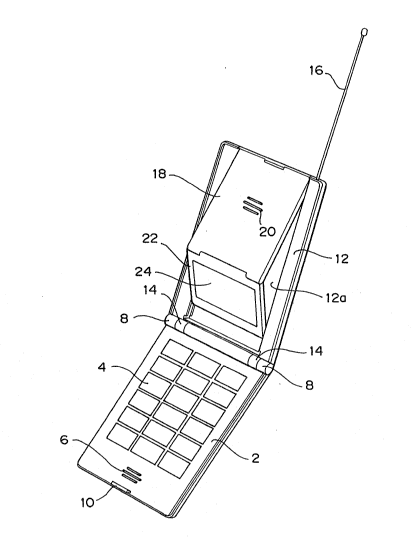
A folding portable telephone set in a first embodiment
according to the present invention will be described here-
lo inafter with reference to Figs. 1 to 14. Referring mainlyto Fig. 1, a first flat segment 2 is provided with a
switching unit 4 having a dialing function, a built-in
microphone 38 disposed under a perforated portion 6, and a
built-in telephone logic unit 28. The first flat segment 2
is provided on its one edge with a pair of knuckles 8 and
with a ca~ch 10 near the opposite edge.
A second flat segment 12 is provided internally with a
transmission-reception circuit. The second flat segment 12
is provided on its one edge with a pair of knuckles 14. In
jointing the first flat segment 2 and the second flat
segment 12, the knuckles 14 of the second flat segment 12
are placed in alignment with the knuckles 8 of the first
flat segment 2, and the first flat segment 2 and the second
flat segment 12 are jointed ~y a hinge joint mechanism,
which will be described later, so that the second flat
, . - .
~; ,, : , , ~ :
segment 12 is able to turn on the hinge joint mechanism
relative to the first flat segment 2. The second ~lat
segment 12 is provided in its ~ront surface with a shallow
recess 12a having a width substantially eSIual to that o a
third flat seg,ment 18 and a fourth flat segment 22.
telescopic antenna is stored in the second flat segment 12.
The third flat segment 18 is jointed to the second
flat segment 12, and is provided internally with an earphone
46 under a perforated portion 20. The fourth flat segment
lo 22 is provided with a display unit 24 and is jointed to the
third flat segment 18. The fourth flat segment 22 can be
held at a predetermined angle to the second flat segment 12
by a holding mechanism, which will be described later.
The folding portable telephone set is unfolded for use
lS in a state shown in Figs. 1 and 2. The folding portable
telephone set is folded up for carrying in a state shown in
Fig. 3 by retracting the telescopic antenna 16 into the
second flat segment 2, placing the third flat segment 18 and
the fourth flat segment 22 in the recess 12a of the second
flat segment 12, and then turning the second flat segment 12
to place the same on the first flat segment 2.
Referring to Fig. 4 showing a flexible printed wiring
board 26 employed in the folding portable telephone set in
the first embodiment, the flexible printed wiring board 26
is provided with the telephone logic unit 2~, a
- , . . ; .: : . , : - , :
... .. :- .... - - . .
... . ~: ~ ,. :. , .
.: . : ~. -
~S ~ r~
transmission-reception unit 30, a receiving unit 32, and a
LC~ unit 34. A membrane swltch 36 is connected to the logic
circuit 28 by a connector 37. The microphone 38 is mounted
on the telephone logic unit 28. A pair of power feed
terminals 40 are attached to the backside of the logic unit
28. When a battery pack 42 is mounted on the first ~lat
segment ~, a pair of terminals 44 of the battery pack ~2 is
connected to the power feed terminals 40. The antenna 16 is
connected to the transmission-reception unit 30; the re-
lo ceiving unit 32 is provided with the earphone 46; the LCDunit 34 is provided with a LCD 48.
The construction of the folding portable telephone set
in the first embodiment will further be described with
reference to Fig. 5. The first flat segment 2 comprises the
logic unit 28 of the flexible printed wiring board 26, and a
casing consisting of a front casing 50 and a rear casiny 52
and containing the logic unit 28. The battery pack 42
containing a plurality of batteries 43 is joined detachably
to the rear casing 52. The second flat segment 12 comprises
the transmiss.ion-reception unit 30 of the flexible printed
wiring board 26, and a casing consisting of a front casing
54 and a rear casing 56 and containing the transmission-re~
ception unit 30. The third flat segment 18 comprises the
receiving unit 32 of the flexible printed wiring board 26,
provided with the earphone 46, and a casing consisting of a
, . . . .
' ` .~ , ' ~ ;~
,: :,,
:, :~
r
front casing 58 and a rear casing 60 and containing the
receiving unit 32. The fourth flat segment 2~ comprises the
LCD unit 34 of the ~lexible printed wiring board 26, pro-
vided with the LCD 48, and a casing consisting of a front
casing 62 and a rear casing 64 and containing the LCD unit
34. A transparent window 24 is formed in the front casing
62 of the fourth flat segment 22.
A hinge joint mechanism jointing the first flat
segment 2 and the second flat segment 12 will be described
lo with reference to Figs. 6 to 8.
As best shown in Fig. 7, the knuckles 8 of the first
flat segment 2 are provided with through holes 9, and the
knuckles 14 of the second flat segment 12 are provided with
through holes 15. As shown in Fig. 8, a slit 17 for re-
ceiving one end of a torsion spring 66 is formed near eachof the knuckles 14 of the second flat segment 12. The
torsion spring 66 is interposed between each knuckle 8 and
the corresponding knuckle 14, hinge pins 68 are inserted
through the through holes 9 of the knuckles a into the
corresponding through holes 15 of the knuckles 14, and then
snap rings 70 are put in the respective annular grooves 68a
of the hinge pins 68 to joint the second flat segment 12 to
the first flat segment 2. The gap between the first flat
segment 2 and the second flat segment 12 is covered with a
pair of corrugated strips 72 to protect the flexible printed
,
~. : .
,: -, - . :
., . :
12
wiring board 26 contained in the flrst flat segment 2 and
the second ~lat seyment 12.
Referrin~ to Figs. 9 and 10, A pin 76 fixed to one end
of one edge of the third flat sesment 18 i.s inserted in a
hole 77 formed in one end of the other edge o the second
flat segment 12 (Fig. 10). A pin 78 inserted a hole formed
in the other end of the same edge of the third flat segment
18 and biased outward, namely, in the direction of the arrow
E, by a spring 80 is received in a hole 79 formed in the
other end of the same edge of the second flat segment 12.
In jointing the third flat segment 18 to the second flat
segment 12 so that the third flat segment 18 is able to turn
relative to the second flat segment 12, the pin 76 is
inserted in the hole 77 of the second flat segment 12, and
then the pin 78 is inserted in the hole 79 of the second
flat segment 12.
The fourth flat segment 22 is jointed to the third
flat segment 18 with a pair of pins 82 and 84 so that the
fourth flat seyment 22 is able to turn relative to the third
flat segment 18. A torsion spring 86 is wound on the pin 82
to bias the joint of the third flat segment 18 and the
fourth flat segment 22 in the direction of the arrow F as
shown in Fig. 12.
A pair of pins 88 are ixed to the opposite ends of
the free edge of the fourth flat segment 22. Grooves 74 are
,
- :: ' .. . : '
. .: . , : :
13 2 , ~ ~ ~
formed respectively in the side surfaces oE the recess 12a
of the second flat segment 12. The pins 88 are inserted in
and moved along the yrooves 74 in the direction o the arrow
shown in Fig. 11 as far as the pins 88 drop into recesses
74a formed at the depths of the grooves 74, respectively, to
set the fourth 1at segment 22 at a predetermined angle to
the second flat segment 12.
A projection 90 is formed on one side surface of the
third flat segment 18. The projection 90 is fitted in a
lo recess 92 formed in one side surface of the recess 12a of
the second flat segment 12 to lock the third flat segment 18
to the second flat segment 12. As shown in Fig. 13, slits
94 are formed in the side surface of the third flat segment
18 on the opposite sides of the projection 90 to enable the
projection 90 to be distorted el~stically. When the third
flat segment 18 is depressed in the direction of the arrow G
(Fig. 13), the projection 90 is fitted in the recess 92 to
lock the third flat segment 18 to the second flat segment
12.
In Figs. 9 and 14, indicated at 96 is an unlocking
mechanism. As best shown in Fig. 14, a lever 100 is sup-
ported pivotally on a pin 98 in a cavity 97 formed in the
second fla~ se~ment 12. When one end 102 of the lever 100
is depressed, the other end 104 of the same rises to release
the third flat segment 18 from the second flat segment 1~.
- .. -. . .. .
~'. - , , ~ ,
.: - . . .
14 2 . ~
In using the folding portable telephone set, the flat
segments are set respectively in positions as shown in Figs.
1 and 2; that is, the second flat se~ment 12 is extended so
that an obtuse angle is formed between the first Elat
segment 2 and the second Elat segment 12, the third flat
segment 18 is extended toward the first flat segment 2 so
that an acute angle is formed between the second flat
segment 12 and the third flat segment 18, and then the pins
88 fixed to the opposite ends of the free edge of the fourth
lo flat segment 22 are fitted in the recesses 74a formed at the
extremities of the grooves 74 to secure the third flat
segment 18 and the fourth flat segment 22 with a predeter-
mined obtuse angle therebetween. After thus unfolding the
folding portable telephone set, the earphone provided on the
third flat segment 18 is set to the ear. In this state, the
microphone is located near the mouth for transmission.
In folding up the folding portable telephone set, the
pins 88 are removed from the recesses 74 of the second flat
sesment 12, the third 1at segment 18 and the fourth flat
segment 22 are placed flat in the recess 12a of the second
flat segment 12, and then the second flat segment 12 is
turned down on the fixst flat segment 2 as shown in Fig. 3.
A folding portable telephone set in a second embodi-
ment according to the present invention will be described
hereinafter with reference to Figs. 15 to 22.
- - ": . :
- . ~ , . , .
F~ r~
The fol.ding portable telephone set comprises a first
~lat segment 112, a second flat segment 120 and a third flat
segment 128. The first flat segment 112 :is provided in-ter-
nally with a transmission-reception circuit, not shown, and
a switching unit 114 having a dialing function. A battery
pack, not shown, is combined detachably with the first flat
segment 112. The first flat segment 112 has a perforated
portion 116 near one edge thereof, and is provided on the
other edge thereof with a knuckle 118 providPd with a pair
of holes 118a in the opposite ends thereo~. A microphone
is disposed under the perforated portion 116.
The second flat segment 120 is provided with a display
unit 122 having a built-in LCD. A pair of knuckles 124
respectively having holes 124a are formed on one edge of the
second flat segment 120 adjacent to the first flat segment
112. Hinge pins are inserted in the holes 118a of the
knuckle 118 of the first flat segment 112 and the holes 124a
of the knuckles 124 of the second flat segment 120 to joint
the second flat segment 120 to the first flat segme~t 112 so
that the second flat segment 120 can be turned down on the
first flat se~ment 112. A grove 126 for storing an antenna
134 is formed in one side portion of the second flat segment
120. A pair of knuckles 136 provided with holes are formed
on the other edge of the second flat segment 120.
A knuckle 138 provided with holes in the opposite ends
.
.
.~
16 2
thereof i5 formed on one edge of the third flat segment 138
adjacent to the second flat segment 120. As shown in Fig.
22, pins 140 are inserted in the holes of the knuckles 136
of the second flat segment 120 and the kmlc~le 138 of the
third flat segment 128 to joint the third flat segment 128
pivotally to the second flat segment 120. The third flat
segment 128 has a perforated portion 130, and is provided
with an earphone under the perforated portion 130. A groove
132 for storing the antenna 134 is formed in one side
portion of the third flat segment 128.
Referring to Fig. 22 showing a holding mechanism for
holding the third flat segment 128 on the second flat
segment 120 at a predetermined angle to the second flat
segment 120, the knuckles 136 of the second flat segment 120
are provided integrally with protrusions 142, and the
knuckle 138 of the third flat segment 128 is provided with
recesses 144a at positions corresponding to the protrusions
142. In extending the third flat se~ment 128 at the prede-
termined angle to the second flat segment 120, the third
flat segment 128 is turned relative to the second flat
segment 120 until the protrusions 142 drop into the recesses
144a. Thus, the third flat segment 128 is held on the
second flat segment 120 in a position shown in Fig. 22 by
the engagement of the protrusions 142 and the recesses 144a.
By engaging the protrusions 142 of the second flat
,, :. . . .
: ., ::: . :~
17 ~ J
segment 120 with other recesses 144b formed in the third
flat segment 12~, the second and third flat segments 120 and
128 are held flat as indicated by phantom lines in Fig. 22.
In using the folding portable telephone set, the
second flat segment 120 is extended in one direction so as
to form an obtuse angle between the first flat segment 112
and the second flat segment 120, and then the third flat
segment 128 is extended in the opposite direction so as to
fo.rm an obtuse angle between the second flat segment 120 and
the third flat segment 128. As shown in Fig. 22, the third
flat segment 128 is held so that the predetermined obtuse
angle is formed between the second flat segment 120 and the
third flat segment 128. When the earphone provided on the
third flat segment 128 is set to the ear, the microphone
provided on the first flat se~ment 112 is located near the
mouth for transmission.
In folding up the folding portable telephone set, the
second flat segment 120 and the third flat segment 128 are
turned down flat on the first flat segment 112~ Since the
total lenyth of the second flat segment 120 and the third
flat segment 128 is approximately egual to the length of the
first flat segment 112, the folding portable telephone set
can compactly be folded up.
~;
, , ,~, "
. :
. . ~