Note: Descriptions are shown in the official language in which they were submitted.
~ ~9l/00655 PCT/US90/02679
`` 2 ~ 2
~eeeiver With Varia~l~ predetectiQn-Ban~wi~h
Based on Expe~t~ a Rate
sackground of the Iny~n~lQ~
This inventlon relates to selective call receivers,
such as paging receivers, employing variable data rates.
Current paging receivers operate on a variety of
signaling code formats that can all be detected using a
10 consistent (fixed) IF bandwidth. Examples of existing code ;`
formats and their respective bit rates in bits per second
(BPS) are:
Motorola GSC: 300 BPS Address /600 BPS Message
POCSAG: 512 BPS
POCSAG: 1200 BPS
NEC D2, D3: 200 BPS
NEC D9: 512 BPS
, .
It is within the performance capability of today's
receivers and transmitters to achieve consistent system
sensitivity at these low bit rates.
In order to achieve higher throughput of information,
it is advantageous to use higher bit rates, for example
2400, 4800, and conceivably 9600 BPS. However, it would be j
desirable to provide a pager which could operate on ~` -
existing paging systems, e.g. at 1200 BPS and could also
operate at higher bit rates to give increased capacity ror
30 future system expansion. With the higher bit rate system ~-
operation there is a need to compensate for the loss in
energy per bit by adding additional transmitters. These
added transmitters fill in the coverage areas where the
received signal is inadequate for acceptable higher bit
~5 rate operation. In this way, by adding further
transmitters and increasing the bit rate, the capacity of
the overall system can be increased substantially. In
changing from 1200 to 4800 BPS, only an additional 6db of
:.
. :.:: .: : : : , ::
.: , .. ~ : -
: - ~ :
. .
WV91/0~655 2 o ~ 2 2 P~/US90~0267
signal is required to compensate for this loss whereas the
throughput capacity is quadrupled. In addition, it would
also be desirable to provide a paging system with the
capability of paging different pagers at different bit
rates, because greater range is achievable with lower bit
rates. In order to achieve optimum range, for each system
operation however, it is important to optimize the band
width of the IF filter. The narrow bandwidth IF filter
required at the lower bit rates would be unsuitable for the
higher bit rates.
U. S. Patent 4,642,632 describes a paging system in
which an address code is transmitted at a lower
transmission rate than the message code. The receiver
includes a low pass filter which Pilters the signal at the
post-detection stage, immediately prior to the bit slicer.
The low pass filter has a cut-off frequency 5witchable
between the reception rate for the address and the
reception rate ~or the mes~age~ This .L9 don~ to maxirn.tze
the paging code reception pro~babillties at both data rates.
According to the invention, there is provided a
selective call receiver and system and a method of
25 operation thereof. The receiver comprises means for ~
receiving a modulated data signal having a variable bit -:
rate and including a code indicative of the bit rate; a
demodulator; a bandpass filter for filtering the signal
prior to demodulation in the-de~odulator, the bandpass
filter having an adjustable bandwidth; and means for
adjusting the bandwidth of the bandpass filter in response
to the code received.
By this means, the bandwidth of the filter can be
selected according to the bit rate of the receiv~d signal,
as indicated by the code lncluded in the signal. In this
way, a signal ha~ing a low blt rate can be filtered through
a narrow bandwidth filter, thereby giving a good signal-to-
09l/0~5; PCT/USgO/Q2679
noise ratio, while a higher bit rate requiring a widerbandwidth to prevent intersymbol interference can be
filtered through a wider bandwidth filter.
The invention results in improved overall performance.
A preferred embodiment of the invention will now be
described, by way of example, with reference to the
accompanying drawings.
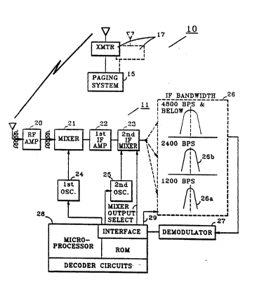
Figure 1 shows a paging system having a transmitter -
and a receiver, in accordance with the invention.
Figure 2 shows the format of the slgnal transmitted by
the transmitter of Figure l.
Flgure 3 show9 the pre~etection ~llter o~ ~h~ receiver
o F Figure 1.
Deta:lled DesoriDtlon Q~ the Tnv~n~,ion
Referring to Figure 1, there is shown a paging
transmitter lC and a paging receiver 11. The transmitter
10 comprises a paging system controller 15 and one or more
transmitters 17. The receiver 11 comprises an RF amplifier
20, a first mixer 21, a first IF amplifier 22 and a second
mixer 23. First and second oscillators 24 and 25 provide
signals to the first and second mixers 21 and 23
respectively. The first: oscillator-24 is crystal
controlled. A variable IF bandwidth filter is shown
generally at 26, receiving an IF signal from second mixer
23 and passing the filtered signal to a demodulator 27. A
microprocessor 28 is shown, with control lines connected to
the second mixer 23, the oscillators 24 and 25 and the
filter 26.
In operation, the transmitter 10 transmits a signal
having the format shown in Figure 2. On this figure, there
. . :
.. ..
W091/00655 PCT/US90/026~1~
2 ~ 4 ~7
is shown line 30 which illustrates on a small scale the
structure of a complete frame of page data. The frame
comprises a sync portion 31 followed by page data 32. The
page data portion 32 may contain addresses and data for
paging receivers. Together the blocks 31 and 32 comprise a
single frame of page data. At the end of this frame,
another frame begins, i.e. the sequence of sync portion and
frame portion repeats itself.
At the bottom of Figure 2, sync portion 31 is shown in
a larger scale, from which it can be seen that portion of
the frame comprises a settling signal A, bit/word sync
signal B, and a frame information signal C.
Settling signal A includes at least 24 bits which
provldes time ~or receiver stabilization. The 24 hits may
cons~st of an alternating "1" "0" pattern. The bit/word
sync signal B, may consist o~ a 32 bit predetermined
pa~tern which provides for bit ~nchroni~iation and frame
synchronization. The frame lnformation signal C comprises
a 32 bit code word which is structured as a 31,21 BCH code
word with one additional bit of parity. Thus, the frame
information signal C has 21 information bits which may be
made up as follows:
6 BITS -- FRAME NUMBER (00-63) .-
3 BITS - FRAME SPEED (600,1200, 2400, 4800, 9600,19.2K,
38 . 4K, X)
12. BITS. -- SPARES: :
It can be seen that the frame information signal
includes a signal which indicates the frame speed. This
signal is comprised within three bits which are capable of
indicating 8 speeds, these being 600, 1200, 2400, 4800,
9600, 19.2Y and 38.4IC, wlth capaclty for one ~urther speedi.
In the remainder of the description which follows, the case
will be described where only the speeds 1200, 2400 and 4800
BPS are used.
.
~091/00655 ` PCT/U~90/02679
8 ~ 2
The system operates as follows. The transmitter puts
together the sync portion of the frame in controller 15;
Depending on the volume of traffic and~or other factors,
the controller 15 will determine the three bits within
frame information signal which indicate the fxame speed.
The transmitter 17 transmits the sync portion 31 of the
frame at a predetermined speed of 1200 bits per second.
Corresponding to the beginning of the first block of :~::
portion 32, the transmitter 17 switches to the bit rate of
the frame, for example 2400 BPS, and the remainder of the
frame 32 is transmitted at the higher bit rate.
The receiver 11 receives this signal, which is
amplified in amplifier 20, mixed down to an IF frequency by
mixer 21 and oscillator 29, ampli~ied in amplifl.~r 22,
further mixed down in the frequency by mixer 23 and
oscillator 25, and then filtered by Eilt~r 26. Th~
~iltered signal ~rom f:Llter 26 i9 demodulated at 1200 BPS
in demodulator 27, and the bit stream derived ~rom the
signal is fed to microprocessor 28. On receipt of the
frame info code word D or E, microprocessor 28 identifies
the bit rate of the ~orthcoming ~rame, whereupon it adjusts
the bandwidth of IF filter 26 via control line 29. In
25 response to a signal from control line 29, filter 26 ;
changes its bandwidth. In the present case, with the
forthcoming frame bit rate determined as 2400 BPS, and the ;~
rate of the sync portion being 1200 BPS the filter 26
switches from the na~row bandwidth 26a to the intermediate
bandwidth 26b. This is necessary because the narrow
bandwidth, while giving better signal-to-noise at 1200 BPS,
is too narrow for a 2900 BPS signal. One possible manner
in which this change is implemented is illustrated in
Figure 3.
Referring to that figure~ three ceramic ~ilters are
shown 40, 41 and 42. Filter 40 has a typical bandwidth of
5.5 KHz ~ or - 10%. Filter 41 has a typical bandwidth of
WO91/0~65~ 2 0 ~ ~ ~ 9 2 PCT/US90/0267~
8.25 KHz + or - 10% and filter 92 has a typical bandwidth
of 11 KHz + or - 10~. A CMOS analog switch 43 is provided
of the type MC14066B. The filter circuits 26 receives
inputs from the second mixer 23 and provide the inputs to
the filters 90,41 and 42. There is a three-bit control
line 29 from the microprocessor 28 to the switch 93. The
outputs of the filters 90, 41 and 42 are connected to an IF
amplifier 45, which is connected to the demodulator 27.
The filter operates as ~ollow5. On receipt of the
frame speed code (1200 BPS), the microcomputer 28 provides
a signal on control line 29 which operates analog switch 43
to remain connected to IF amp 45 from filter 40 for
continued 1200 BPS operation. In this instance filters 41
and 42 are isolated from the IF amp 95.
If the frame 5peed i~ to be changed ~rom 1200 BPS to
4800 BPS, the microcomputer 28 rec~lves the appropriate
~rame speed code, and causes the switch 43 to dlsconnect
filter 40 and connect the IF arnp ~5 to the ~ilter 42. In
this instance, filters 40 and 41 are isolated from the
circuit.
The demodulator 27 acts as a frequency discriminator,
and the possible choices could be: at the bit rate of 1200,
the high and low bit frequencies are at the carrier
frequency + or -2.2KHz, at the bit rate of 2400 BPS, the
frequencies are carrier + or -3.8 KHz. At 4800 BPS, the
: ~requencies-are carrier ~ or -4.5 KHz.
:: 30
It should be understood that there may be numerous
other ways of implementing the invention, particularly in
implementing the variable bandwidth filter 26. It will
also be appreciated that the filter 26, may be capable of
providing two ~andwidths only, or more than three
bandwidths, and for example wider bandwidths may be
provided for higher bit rates such as 9600 BPS, 19.2 K and
38.4 K. It should be further appreciated that the receiver
~ O91/0065~ PCT/US90/02679
7 . : 2 ~
of the present invention may alternately be constructed ~ -
with a single intermediate frequency, thereby eliminating ~:
elements 22, 23 and 25 from Figure 1. Alternately, more
than two intermediate frequencies may be used.
What is claimed is: