Note: Descriptions are shown in the official language in which they were submitted.
WO ~/11201 2 0 5 ~ 9 ~ ~ PCT/GB~/~
VEHICLE SUSPENSION SYSTEM
DESCRIPTION
This invention relates to a suspension system
for a set of vehicle wheels, of the type including
a stabiliser (anti-roll) bar or tube and is especially,
but not exclusively, related to such a suspension
system for heavy commercial vehicles, such as trucks,
coaches, buses and plant.
In existing vehicle suspensions, it is known
to use a stabiliser (anti-roll) bar or tube mounted
transversely of the vehicle frame (chassis), to act
in a parallel sense to an associated pair of springs
(leaf springs). Such an arrangement stiffens the
vehicle suspension in roll but not during total axle
movement.
A typical stabiliser (anti-roll) bar or tube
for, say, a truck, comprises a generally U-shaped
torsion bar or tube with its otherwise free pair of
ends connected to an associated axle of the truck
by means of, say, shackles and with the base portion
of its U connected to transversely spaced points on
the vehicle frame (chassis). In the case of a torsion
bar, this usually takes the form of a spring steel
rod formed into the desired U-shape, although it can
be of tubular construction.
Although there are several variations of this
known stabiliser (anti-roll) bar or tube arrangement,
such as, having the bar or tube connected between
pairs of leaf sprin-gs on opposed sides of an associated
vehicle, the basic purpose of the bar or tube is to
wo go~ 2 ~ ~j O ~ PCT/GB90/~
resist any axle rolling movement relative to the vehicle
frame (chassis) and axle, or an associated spring
assembly located at or adjacent the axle, by means
of shackles which allow pivoting of the respective
components with respect to each other and the chassis,
thereby allowing for geometrical change in the configur-
ation of the suspension during use thereof.
It is an object of the present invention to provide
an improved vehicle suspension system with enhanced
anti-roll characteristics which, in turn, provide
better vehicle handling, particularly under adverse
driving surface conditions.
It is another object of the invention to provide
an improved vehicle suspension system which affords
a comparatively soft suspension during normal total
axle movement but which provides a comparatively stiff
anti-roll characteristic capable of resisting at least
a major proportion of any roll attempted by the asso-
ciated vehicle.
It is a further object of the invention to provide
an improved vehicle suspension system which affords
little or no anti-roll characteristic for an unladen
vehicle, thereby providing a smoother and more comfort-
able ride, but which affords the required anti-roll
characteristics when the vehicle is laden.
.
It is yet a further object of the invention to
provide an improved vehicle suspension system which
affords a comparatively soft, low frequency ride and
good inter-axle articulation with comparatively high
roll resistance.
WO ~/11201 2 0 ~ ~ ~ 2 ~ PCT/GB90/ ~ 36
Accordingly, one aspect of the invention resides
in a suspension system for a vehicle wheel set, com-
prising first suspension means, second suspension
means and stabilising means arranged generally trans-
versely of the longitudinal axis of an associatedvehicle and arranged to act in conjunction with at
least one of said first and second suspension means,
to provide the vehicle with an anti-roll characteristic
when operating under certain conditions.
Preferably, the second suspension means is con-
nected to, and may be mounted upon, the stabilising
means. In one embodiment, the second suspension means
is located on the longitudinal axis of the associated
vehicle and can be secured to the chassis thereof.
Preferred forms of the second suspension means include
a leaf spring, coil spring, hydraulic, pneumatic or
rubber (elastomeric) suspension arrangement or, indeed,
any combination thereof.
In other embodiments, the first suspension means
is arranged on respective opposed sides of the asso-
ciated vehicle, with the stabilising means being ar-
ranged to act in conjunction with the secondary suspen-
sion means. The first suspension means may also com-
prise spring means arranged on respective opposed
sides of the vehicle, with the stabilising means con-
nected therebetween. Also, the stabilising means
may be connected to the vehicle chassis by a pair
of arms, preferably articulated with respect to the
stabilising means and/or the chassis, which are arranged
on respective opposed sides of, and extend generally
longitudinally of, the vehicle. The end of each arm
may be connected to the vehicle chassis by means of
~5 a shackle or by means of a controllable actuator of
WO 90/11201 PCI/GB90/00436
~ J _1 3 .'. ~
an active ride arrangement, to render the suspension
system "active" or "semi-active". This arrangement
of suspension system can use both powered actuators
and cylinders acting as dampers and adjustable, by
powered or switchable valves, from zero damping
to virtually solid damping.
A preferred form of stabilising means comprises
- an anti-roll bar or tube whose ends may be extended
or extendable to form a generally U-shaped configuration
whose free ends can be secured to respective ends
of an axle of the associated vehicle.
Alternatively, the stabilising means may comprise
actuators attached to the vehicle chassis and in one
series of embodiments, the first and second suspension
means are arranged in mechanical series with each
other. Other embodiments have the suspension means in
parallel.
In another embodiment, the position of the stabil-
ising means with respect to the first and second suspen-
sion means may be adjusted longitudinally of the vehicle.
In accordance with another aspect of the invention,
there is provided stabiliser (anti-roll) means for
use in a vehicle suspension system, consisting of
a composite arrangement comprising a torsion bar or
tube and a pair of leaf spring arms, one end of each
arm being connected or connectable to an associated
leaf spring.
Preferably, the other end of each leaf spring
arm is connected or connectable to the respective
end of an axle of the associated vehicle. Also, the
positioning of the torsion bar or tube longitudinally
WO90/11201 2 ~ PCT/GBgO/~
of the pair of leaf spring arms may be adjustable,
to facilitate "installation" of any associated sus-
pension system in which the composite is incorporated.
5Also provided is a vehicle wheel set suspension
system as defined above, arranged in tandem or other
multiple axle combinations thereof.
In order that the invention may be more fully
understood, various embodiments in accordance therewith
will now be described by way of example and with refer-
ence to the accompanying drawings in which each Figure
includes a side elevational view and a plan view of
a particular embodiment and wherein:
Figure l is a first embodiment of suspension
system for a vehicle wheel set, in accordance with
the invention
20Figure 2 is a second embodiment of vehicle wheel
set suspension system in accordance with the invention;
Figures 3 and 4 are two modifications of the
second embodiment of vehicle wheel set suspension
system of Figure 2;
Figures 5 and 6 are two further modified forms
of the second embodiment of Figure 2;
30Figure 7 is a third embodiment of the inventive
vehicle suspension system;
Figure 8 is a modified form of the third embodiment
of Figure 7;
WO90/11201 PCT/GB90/~
2~0~2~
Figure 9 is a further modification of the third
embodiment of Figure 7;
Figure 10 is a prior art arrangement of vehicle
S suspension system;
Figure 11 is a fourth embodiment of a vehicle
wheel set suspension system in accordance with the
invention;
Figures 12 to 14 are three modifications of the
embodiment of Figure 11; and
Figure 15 is a composite arrangement for a stabil-
ising (anti-roll) means in accordance with another
aspect of the invention.
Referring firstly to Figure 1 of the drawings,
a suspension system for a vehicle wheel set (not shown)
comprises a first or primary suspension means 11 in
the form of a single leaf spring 13 with an upturned
eye 14 at an end thereof, such a spring 13 being mounted
on either side of the frame or chassis (not shown)
of an associated vehicle. A front axle wheel set
suspension system is shcwn but, equally, the system
can be associated with the rear and/or other axle
wheel set of the vehicle.
A stabilising, anti-roll bar or tube 15 has its
otherwise free ends 16 connected to respective ends
of the leaf springs 13. Mounted upon the anti-roll
bar or tube 15, centrally thereof, is secondary suspen-
sion means 12 in the form of a coil spring, pneumatic
or other suitable suspension arrangement, which can
be single, dual or multiple per axle and which acts
wo go/11201 2 ~ 2 ~ PCT/GB~/~
between the leaf springs 13, via the anti-roll bar
or tube 15, and the vehicle chassis to which it is
secured. In this manner, with the primary suspension
means 11 and the secondary suspension means 12 being
5 employed in mechanical series with each other and
with the anti-roll bar or tube 15 acting in conjunction
with at least the primary suspension means 11, there
is provided a comparatively soft suspension during
normal, total axle movement but a comparatively stiff
10 anti-roll characteristic capable of resisting at least
a major proportion of any roll attempted by the vehicle.
Figures 2 to 6 show various forms of a second
embodiment of inventive vehicle wheel set suspension
15 system, wherein secondary suspension means is employed
again in mechanical series with primary suspension
means but with the stabilising means acting in conjunc-
tion with the secondary suspension means, rather than
the primary suspension means as in the case of the
20 embodiment of Figure 1.
Here again, the effect is to provide a compara-
tively soft suspension during normal, total axle move-
ment. The seconday suspension means, which may be
25 in any suitable form, for instance, another leaf spring,
coil spring, hydraulic, pneumatic, rubber (elastomeric)
suspension arrangement or any combination thereof,
is provided with a comparatively stiff, stabilising
anti-roll bar or tube capable of resisting at least
30 a major proportion of any roll attempted by the vehicle.
As a consequence, the secondary suspension means,
in whatever suitable form, can, if the anti-roll effect
is sufficient, be installed with less consideration
for spacing across the vehicle chassis to provide
35 the necessary anti-roll characterisitc. Also, the
WO ~/11~1 PCT/GB~/~
2 a ~
second suspension unit can be single, dual or multiple
per axle.
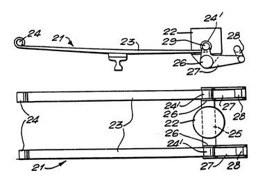
In more detail and with reference to Figure 2,
a first or primary suspension means 21 is constituted
by a pair of ~eaf springs 23 disposed on opposed sides
of a vehicle chassis (not shown) and having at respec-
tive ends thereof upturned eyes 24, 24', with the
eyes 24 being connected to the chassis. Opposed ends
26 of an anti-roll bar or tube 25 are connected to
respective arms 27 which, at one end, are connected
to the chassis by associated shackles 28 and, at the
other end, to the respective eyes 24' by bushes 29.
Although a single leaf spring arrangement is shown
for the first or primary suspension means 21, any
other suitable form of leaf spring arrangement may
of course be used, such as a multiple one.
WO ~J11201 PCT/GB~
~. ~ 0 5 ~ g 2
g
Secondary suspension means in the form of, say,
a coil spring 22, is mounted upon the bar or tube
25 to act in con~unction therewith.
A modified form of the second embodiment described
with reference to Figure 2 can use a pneumatic (air)
, secondary suspension means, as referenced at 22, or
any of the other secondary suspension means referred
to above in relation to the first embodiment of Figure
1.
The modification shown in Figure 3 comprises
a primary leaf spring suspension means 31 having upper
leaves 33' and lower leaves 33'' with each end 36
of an anti-roll bar or tube 35 being connected by
a bush 39 to each lower pair of leaves 33" of the
primary suspension means 31 and to the chassis via
arms 37 and shackles 38. Associated with the anti-
roll bar or tube 35 is a secondary suspension means
in the form of a pneumatic (air) "springr 32.
A further modification shown in Figure 4 which
also includes a lowermost, rear elevational view as
Figure 4A, comprises a ~ehicle wheel set suspension
system similar to that described above in relation
to Figure 3, with primary leaf spring suspension means
41 having, in this case, two upper leaves 43, 43'
and a single lower leaf 43'' on opposed sides of the
chassis. Secondary suspension means 42 is, however,
in the form of a chevron-shaped rubber suspension
block 42 or rather, a pair thereof. Otherwise, the
anti-roll bar or tube 45 and the other suspension
components are substantially the same, namely the
bushes 49 associated with the ends 46 of the bar or
tube 45 the arms 47 and the shackles 48.
- ,~
WO ~tll201 PCT/GB~
g ~05~g2 1~
-- -- 10 --
An extension of the various forms of the second
embodiment of inventive vehicle wheel set suspension
system discussed above in relation to Figures 2 to
4, is to couple together two axle~ each incorpora~ing
such a suspension system with the secondary suspension
means. For example, connection between secondary,
pneumatic (air) spring suspension means 52 mounted
on the anti-roll bars or tubes 55, such as those shown
at 22 and 32 in Figures 2 and 3 would give equalised
or controlled loads between axles, thereby producing
an effective four spring tandem suspension, as shown
in Figure ~. Here, this tandem arrangement comprises
a pair of suspension systems each indicated generally
at 50, as described above in relation to Figure 2,
with their secondary, pneumatic spring suspension
means 52 connected together by a conduit 150, although
it can be seen that the arms 57, and associated bushes
59 and shackles 58, are oriented in the opposite sense
to that of the corresponding components of Figure
2 but in the same sense as those components of Figures
3 and 4.
Such an arrangement provides a comparatively
soft, low frequency ride and good inter-axle articu-
lation with comparatively high roll resistance.
.
This improved axle articulation could be improvedfurther by interconnecting, preferably hydraulically,
the loads in the shackles connecting the anti-roll
bars or tubes to the chassis. Such interconnection
could also be effected pneumatically or mechanically.
Only the same side of this tandem arrangement would
be so-connected, thereby allowing each wheel on each
side of the vehicle freedom to move relative to the
3~ other wheel, without anti-roll being brought into
WO ~/11201 PCT~GB~/~
effect, whilst retaining full roll control when both
wheels deflect together. Such an arrangement is shown
in Figure 6, wherein a comparatively, very high arti-
culating four spring suspension can be produced.
In Fiaure 6, two inventive suspension systems
60, such as, the tandem arrangement described above
in relation to Figure 5, have their secondary suspension
means 62 connected together by a conduit 160 and their
anti-roll bars or tubes 65 connected together via
a hydraulic coupling 161 connected to a hydraulic
piston/cylinder assembly 162 for each bar or tube
65.
By replacing the bushes and/or shackles of the
anti-roll bars or tubes of the embodiments described
above with valve-controlled hydraulic actuators or
~ampers, the suspensions could be rendered "active",
uitn powered valves ~eing controllcd by a microprocessor
fed with information r~lating to vehicle chassis motion.
The valves would be operated when the vehicle
sprung mass required support, either to maintain the
vehicle upright or to lean as required dynamically.
An active suspension of this nature is shown in Figure
7 wherein a suspension system 7 similar to that des-
cribed above in relation to Figure 3 is shown, except
that the shackles 38 between the anti-roll arms 37
and the vehicle chassis of that previous Figure 3 are replaced
by actuators or controlled dampers 78 between anti-roll arms
77 and the vehicle chassis.
If the vehicle chassis is stable, then the actu-
ators 78 are free or in a damped mode, so that, on
one wheel bumps, they provide negligible or damped
resistance to such wheel movement, thus effectively
WO90/11~1 PCT/GB90/~
2 ? ~ 6 r 2 ~
- 12 _
isolating the anti-roll arrangement from the vehicle.
As soon as the sprung mass of the vehicle becomes sub-
ject to the influence of exterior forces, for instance,
a strong side wind or camber, the actuator or controlled
damper 78 is brought into operation or the damper set-
ting is changed and, in conjunction with the secondary
suspension means 72 and the anti-roll bar or tube 75,
acts to support the vehicle, thereby providing high
dynamic stability. Thus, this active suspension does
not bear loads under steady state operation, which
is in contrast to known active systems which act direct-
ly upon the wheel(s). Accordingly, the inventive active
suspension system 70 has an advantage over the normal
active ride suspension systems, in that its response
and sophistication need not be as sensitive as the
known systems which act directly upon the wheel(s).
Also, the system could be more failsafe for longer
term durability situations.
Figure 8 shows such an active suspension of the
tandem type, which is similar to the suspension des-
cribed above in relation to Figure 6, with control
lines 181 connecting actuators 18Z together. These
actuators 182 are associated with the arms 87 of the
anti-roll bars or tubes 85 connected between the leaf
springs 83 of primary suspension means 81 and bearing
secondary suspension means 82. Also, further control
lines 183 link the control lines 181 to microprocessor-
controlled valves (not shown) with a conduit 180 linking
the two secondary suspension means 82 together.
Figure 9 shows a modification of the active sus-
pensions described above with reference to Figures
7 and 8, wherein the anti-roll bar or tube is replaced
by other stabilising (anti-roll) means in the form
WO ~/11201 ~1'
- - 13 -
of actuators 95 which are linked directly to the
vehicle chassis and which simulate the action of an
anti-roll bar or tube and secondary suspension means.
The primary suspension means is represented here by
respective lower and upper leaf springs 91, 92, to
the former of which the actuators 95 are attached.
,, In Figure 10, a prior art arrangement of vehicle
suspension system 110 is shown with an anti-roll bar
or tube 105 connected between either or both pairs
of ends of the two leaf springs 101 but with only one
anti-roll bar 105 being employed in this particular
known system. The anti-roll bar or tube 105 is mounted
at 109 to the vehicle chassis (also not shown) by means
of bushes, whilst the remote ends of the spring leaves
101 are also connected to the chassis by shackles 107.
In some circumstances, this mounting arrangement for
the anti-roll bars or tubes 105 would, provide enhanced
mounting points for chassis brackets and would tend
to reduce any bending moments in chassis cross-members.
When both the springs 101 move to the same angular
extent (deflection) during, say, total movement of
the axle 108, the spring deflection and rate would
be generally that of any other conventior.al spring.
When one spring moves in a direction opposite to that
of the other, for instance, during roll of the vehicle,
then the anti-roll bar or tube 105 is in torsion,
resisting such,; movement of the spring 101. If the
anti-roll bar or tube 105 is considered to be infinitely
stiff and the spring movements are considered to be
similar but in opposite directions, then the spring
would deflect as if its end were "encastre", thereby
giving up to four times the normal stiffness in the
associated part of the spring. Such an arrangement
~ ~;
WO90/11201 PCT/GB90/~
~13~
- 14 -
could provide enhanced spring mounting, especially
for composite leaf springs wherein problems arise
with eye mounting arrangements, as well as eliminating
the conventional anti-roll bar arrangements.
In Figure 10, single leaf springs 101 are shown.
However, and as shown in Figure 11, multiple suspension
means in the form of double leaved springs can be
used in accordance with the invention. In this fourth
embodiment, two leaf springs 111 and 112, consituting
respective primary and secondary suspension means,
are used. An anti-roll bar or tube 115 is connected
to the ends of the secondary lower leaf spring 112,
whilst the primary upper leaf spring 111 is connected
to the vehicle chassis in a conventional manner by
means of, say, bushes 119 and/or shackles 117. This
means, of course, that the anti-roll bar or tube 115
need not be connected directly to the chassis, thereby
eli~in~ting any need for associated bushes or chassis
brackets, with the springs 111 and 112 in parallel.
The roll stiffening effect of this inventive
arrangement would be lower than that for a single
leaf spring arrangement but the required extra roll
stability could still be obtained.
In a modified form of this fourth embodiment
of the inventive suspension system shown in Figure
12, an anti-roll bar or tube 125 is connected between
the ends of a secondary lower, full length auxiliary
leaf 122, whilst the primary upper leaf 121 is connected
to the vehicle chassis in a conventional manner with
bushes 129 and shackles 127. One advantage of this
modified arrangement is that the anti-roll effect
only comes into operation when the secondary suspension,
WO ~/11201 PCT/GB~/~
r
-- 15 --
-
auxiliary leaf 122 is in operation. Thus, an unladen
vehicle w~uld not be subject to any anti-roll effect,
because the auxiliary leaf 122 is not operating, such
an effect not normally being required for an unladen
vehicle. This would, of course, give a smoother and
more comfortable ride, because the one wheel bump
condition is free from any anti-roll resistance.
Under laden conditions of the vehicle, however, the
auxiliary leaf 122 becomes effective, thereby providing
the required anti-roll characteristic in conjunction
with the anti-roll bar or tube 125. If necessary,
the auxiliary leaf 122 and associated ends of the
anti-roll bar or tube 125 could be made to act directly
on to the vehicle chassis.
~5
Figures 13 and 14 show two further modifications
of the fourth embodiment, wherein the primary lower,
auxiliary leaf 131, in Figure 13, is secured to the
chassis via bushes 139 and shackles 137 and to the
secondary, upper leaf 132, with anti-roll bars or
tubes 135 connected between both ends of the pair
of upper leaves 132 and to the chassis at respective
points 138. This arrangement would re~uire a compara-
tively large clearance in the vehicle frame ~chassis)
to permit free movement of the bar or tube 135.
In the ~igure 14 modification, two anti-roll
bars or tubes 145 are again connected between respective
ends of a pair of secondary suspension, upper leaf
springs 142 of the system, these bars or tubes being
secured to the vehicle chassis by means of flexible
mounting members 148, with primary suspension, lower
leaf springs 141 being separated from but free to
engage the centre of the upper leaf springs 142.
3~ Again, the primary lower leaf springs 141 are connected
WO ~/11201 ~ PCT/GB90/~
to the chassis via bushes 149 and shackles 147.
Referring now to Figure 15 of the drawings, here
there is shown stabilising means for a vehicle suspen-
sion in accordance with a second aspect of the inventionwhich could be considered as constituting a fifth
embodiment of the first aspect of the invention relating
to a vehicle wheel set suspension system.
In this so-called fifth embodiment, first suspen-
sion means is provided in the form of a single leaf
spring 151 and second suspension means which acts only
in an anti-roll sense and which is in the form of an
auxiliary leaf spring arm 152, a pair of such first
and second suspension means being located on each side
of the associated vehicle. In this case, a composite
anti-roll bar or tube 155 in the form of a thin-walled
tube and the leaf spring arm 152 is provided. One
end of each arm 152 is connected to the leaf spring
151, whilst the other end is connected to the respective
end of the axle lS9 in the usual manner.
In this fifth embodiment, in accordance with the
other aspect of the invention, the major proportion
of anti-roll (stabilising) deflection is provided by
the spans of the leaf spring arms 152 and "tuning"
can be effected by changing the leaves of the arms
152 to suit. Also, the position of the anti-roll bar
tube 155 is adjustable along the length of the leaf
spring arms 152. Thus, the arrangement and config-
uration of the anti-roll tube 155 and the leaf spring
arms 152 can be altered to provide a parallelogram
geometry under most working conditions of the suspension
and/or to suit vehicle component installation clearances
for, say, engines, radiators, the axle differential
WO 90/11201 PCI/GB90/00436
2 a ~ ~ 9 2 ~
- 17 -
housing or the like.
Thus, it can be seen that the invention provides
various vehicle wheel set suspension systems which
are capable of improving the anti-roll characteristic
of a vehicle. Also, it is to be appreciated that
various modifications can be made to the inventive
suspension systems described herein, without departing
from the basic concept of the invention as defined
in the appendant claims.