Note: Descriptions are shown in the official language in which they were submitted.
2050949
COIN TUBE MONITOR AND CONTROL MEANS
BACKGROUND OF THE INVENTION
The present invention relates to a device for monitoring
the coinage in coin tubes and more particularly to a device that
uses acoustical means to sense certain coin movements in the
monitoring of coinage in coin tubes to determine the number of
coins in the coin tubes and to control where newly deposited
coins are directed.
Many devices are in existence for monitoring the coinage in
coin tubes to determine and control the number of coins remaining
in coin tubes for making change and refunds from vending machines
and for maintaining minimum numbers of coins in the tubes. For
the most part, the known coin tube control and monitoring devices
have included mechanical devices such as mechanical coin sensors
or feelers which sense the presence of coins in the coin tubes,
electric switches, optical devices, inductors, and Hall effect
sensors which physically, electrically, optically, or
magnetically sense the presence of coins in the coin tubes. Such
devices typically operate on a go or no go basis in sensing the
coins and/or the number of coins in a coin tube by the condition
of the feeler or switch, or the presence or absence of a light
beam, or the condition of a Hall effect device. Such devices
have been used to determine if a coin tube has enough coins in it
to be able to be operated to payout change to a customer. Some
of these devices are located at the top, the bottom or at an
intermediate location along the coin tube to sense the presence
of coins. Additionally, those devices that use a sensor located
at an intermediate location along the coin tube are used to limit
.-r :
~; :
20S0 9¢ 9
the self-loading of the coin tube above the intermediate level.
Mechanical feelers, switches, optical sensors, inductors, and
Hall effect devices have obvious disadvantages and limitations
including being subject to breaking, failing, sticking and
interfering with coin movements. These devices are also
relatively expensive and are slow acting as compared to
electronic circuit devices and they are relatively susceptible to
jamming and require frequent maintenance and repair. All of
these conditions and limitations of the known monitoring devices
limit their usefulness, cause relatively frequent repair and
maintenance, and increase the cost of operating and maintaining
the coin tubes, and particularly the coin tubes used for making
change in a vending machine. Since the coin tubes in a vending
machine are the usual means chosen for coins to be accumulated
--- for payback it is important that the coin tubes be as clear and
open as possible and free from maintenance and jamming. It is
also important to know how many coins are in the coin tubes at
all times in order to determine whether a deposited coin should
be sent to one of the coin tubes or to a cash box.
One such device for monitoring the coinage in coin tubes is
disclosed in U.S. Patent No. 4,587,984, which is assigned to a
subsidiary of the assignee of this invent-ion. This device
maintains a running total of the number of coins in one or more
coin tubes by adding and substracting coins to establish an
amount to be maintained which is predetermined. In order for
this device to perform properly the predetermined number of coins
stored in each coin tube must be known. Data produced from other
vending control means as a result of deposits made, coins paid
back or refunded, and the difference between the number of coins
deposited that are directed into the coin tubes and the number of
--2--
2050949
... . ~ .
coins that are passed to the cash box are used to determine the
number of coins remaining in the coin tubes. A predetermined
maximum and predetermined minimum number of coins to be
accumulated in each of the coin tubes are also used to direct
coins to a suitable location in the vending machine.
Another device for monitoring the coinage in coin tubes is
shown in U.S. Patent No. 4,491,140 whereby only one level of each
coin tube is sensed to provide correction to the running total
whenever its predetermi.ned level detector indicates a change.
This device maintains a running estimated count of the coins in a
coin tube. This device also includes a sensor which determines
whether the number of coins in the coin tube is greater than a
predetermined number. If the number of coins in the coin tube is
greater than the predetermined number the running estimated count
is modified.
Various limitations of the prior art devices can be seen
when considering the use of coin tubes having increased heights
and numbers which result in increased storage capacities. It is
desirable to provide flexability of coin tube maximum and minimum
amounts as the requirements for making change varies from one
sale price situation to another, and with the acceptance of
certain coins and bill demoninations, i.e., unless the largest
demomination coin is required, for making change if accepting
higher denomination currency. Additionally, as the number of
coin tubes increases due to differing requirements of vending
machines, the prior art devices have to be modified to add more
circuitry, especially replicative circuitry.
ASPECTS OF THE PRESENT INVENTION
It is a principal aspect of the present invention to teach
the construction and operation of novel means to monitor and
-3- ~
`~ 2050949 ".. ~
control the number of coins in one or more coin tubes.
Another important aspect is to sense coin movements in a
coin tube by acoustic means which sense certain movements or
impacts made by the coins as they enter the coin tubes and as
they impact on coins in the tubes.
Another aepect is to acoustically sense more than one coin
movement of a coin in a coin tube using the same acoustical
sensing means.
Another aspect is to provide improved means for maintaining
10 a desired level or number of coins in a coin tube.
Another aspect is to know the number of coins remaining in
a coin tube without having to sense or feel the coins in the coin
tube.
Another aspect is to provide means to electronically
monitor and control the number of coins available for payout or
refund in each coin tube in a vending machine.
Another aspect is to provide means to monitor and control
the number of coins in one or more coin tubes with minimal
replicative circuitry.
Another aspect is to reduce maintenance on vending and
other coin controlled devices.
Another aspect is to simplify the construction of the coin
tubes used in vending machines.
Another aspect is to reduce the possibility of a coin jam
in the coin tubes used in vending machines.
Another aspect is to provide improved coin tube monitoring
and control means which are compatible with existing vending
control circuits.
These and other aspects and advantages of the present
invention will become apparent after considering the following
` 2050949
detailed specification of a preferred embodiment of the subject
invention in conjunction with the accompanying drawings wherein:
BRIEF DESCRIPTION OF THE DRAWINGS
FIGURE 1 is a block diagram showing the circuitry for coin
tube monitoring and control means constructed according to the
present invention;
FIGURE 2 is a perspective view of a set of coin tubes for
use with a vending machine eguipped with the present invention;
FIGURE 3 is a perspective view of one of the coin tubes
shown in FIGURE 2;
FIGU~-~ 4 is a schematic circuit diagram partly in block
form of the coin tube monitor and control means of the present
invention;
FIGURE 5 is a perspective view of a set of coin tubes for
use with a vending machine equipped with another embodiment of
the present invention; and
FIGURE 6 is a flow chart diagram of the operation of a dime
coin tube monitor and control for the embodiment shown in FIGURE
5.
DETAILED DESCRIPTION OF THE PREFERRED ~BOD~NT
Referring to the drawings more particularly by reference
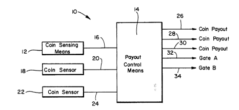
numbers, number 10 in FIGURE 1 refers to a coin tube monitor and
control circuit for use on a vending control device that includes
coin tubes for accumulating coins to be used for payback, refund,
and escrow. The circuit 10 including the coin tubes associated
therewith, is constructed and connected according to a preferred
embodiment of the present invention and many of the circuit
elements can be embodied in a microprocessor or like device. The
circuit 10 is shown for illustrative purposes having provision
2050949
for recognizing, accumulating, and monitoring three different
denominations of coins, i.e. nickels, dimes and quarters, and for
generating signals to represent each different denomination of
coin deposited and certain movements thereof. For example, the
circuit includes a coin sensing means 12 that is used for sensing
data from which the acceptability, validity and denomination of
each deposited coin can be determined. Such devices are well
known and are not per se a part of the present invention. The
coin sensing means 12 are connected to a payout control means 14
--- 10 by lead 16. A signal is sent over lead 16 by the coin sensing
means 12 to the payout control means or microprocessor 14
whenever it is established that a genuine or authentic coin has
been deposited. Additionally, the coin sensing means 12 produces
a signal representative of the denomination of the deposited coin
to the payout control means 14 over lead 16 when the denomination
of the coin has been determined. The number of coins and coin
tubes employed will vary depending on the requirements of each
coin changer, and the circuit 10 can be made to accommodate a
greater or a lesser number of different denomination coins.
The circuit 10 also includes another coin sensor 18 which
is connected to the payout control means 14 via lead 20. The
coin sensor 18 is shown as being an optical detector which
optically detects the passing of a deposited coin into a coin
tube. Although only one coin sensor 18 is shown in FIGURE 1, it
is to be understood that one such coin sensor 18 is associated
with each coin tube. The circuit 10 includes still another coin
sensor 22 connected to the payout control means 14 via lead 24.
The coin sensor 22 in the present construction is an acoustic
sensor that detects certain sounds or frequencies produced by a
deposited coin when it impacts on various elements along its path
20509~9
of movemen~. The sensor 22 can be made to respond to a range of
frequencies that includes the frequency of the coins vibration on
impact.
The payout control means or microprocessor 14 has various
output connections such as those appearing leads 26, 28, and 30,
and these are connected to respective payout motors or solenoids
(not shown) associated with the different denomination coin tubes
wherein coins are accumulated for payback. For example, each
time a signal is present on the lead 26, its associated payback
motor or solenoid will be energized to pay back one quarter coin
from the quarter coin tube. Likewise, when a signal is present
on lead 28, a motor or solenoid will be energized to pay back a
nickel coin from the nickel coin tube, and when a signal is
--~ present on lead 30 a motor or solenoid will be energized to pay
back a dime coin from the dime coin tube.
The payout control means 14 has two other output
connections on leads 32 and 34 which are connected to the
controls for a gate A and a gate B, respectively,-both of the
gates being shown in FIGURE 2. The gates are operated to open
and close depending upon whether an authentic coin has been
sensed by the coin sensing means 12 and whether the coin tubes
are at capacity or have accumulated at least a predetermined
maximum number of coins. For example, the control for gate A
will be operated to direct or prevent an authentic deposited coin
from entering the respective denomination coin tube, and gate B
will be operated to direct or prevent an authentic deposited coin
from going to another location in a vending machine such as a
cash box.
FIGURE 2 shows an arrangement of a coin changer 36 that
includes coin tubes 38, 40, and 42 for use in a vending machine
-
20 50~49 - - -
or like device. The coin tubes 38, 40, and 42 are for receiving
quarters, nickels, and dimes and each has means or an opening 44,
46, and 48 located at its respective upper end for receiving and
directing coins into the coin tubes 38, 40, and 42. Each of the
coin tubes 38, 40, and 42 also has means at its lower end
operable by a respective motor or solenoid to discharge one or
more coins at a time for payback or refund purposes in response
to a signal sent over line 26, 28, or 30.
A coin 50 is shown deposited through an inlet 52 to the
changer and rolls down an upper incline surface 54 past the coin
sensing means 12. Coin sensing means 12 is connected to circuit
means that determine whether the deposited coin 50 is acceptable
or genuine and what denomination it is. This information is sent
to the payout control means 14. If the coin 50 is genuine and
acceptable the payout control means 14 will operate to control
where the coin should be sent such as to one of the coin tubes
38, 40, and 42 or to a cash box 56. If the payout control means
14 determines that the coin 50 should be sent to one of the coin
tubes 38, 40, and 42 a signal is sent over the lead 32 to operate
or open gate A. When the payout control means 14 decides that
the coin 50 should be sent to the cash box 56 a signal is sent
over lead 34 to operate or open gate B so that the coin 50 is
directed along a path indicated by arrow 58 to the cash box 56.
Each of the coin tubes 38, 40, and 42 is shown containing a
stack of coins which are stored for subsequent payout or refund
to a customer. Coin tube 38 contains a stack 60 of quarters,
coin tube 40 contains a stack 62 of nickels, and coin tube 42
contains a stack 64 of dimes.
If it is determined by the means 14 that the deposited coin
50 should be directed through gate A then the deposited coin 50
2050949
passes through gate A and is directed to the appropriate one of
the coin tubes 38, 40, and 42 moving along another inclined path
66. Depending upon the denomination and more specifically the
diameter of the deposited coin 50 it will be directed into the
appropriate one of the coin tubes 38, 40, and 42. A dime will
fit through opening 68 and be directed to the opening 48 of dime
coin tube 42. A nickel will fit through an opening 70 and be
directed to the opening 46 of nickel coin tube 40 and quarter
coins will not fit through either of the openings 68 and 70 and
will instead be directed to the opening 94 at the top of the
quarter coin tube 38. The arrival of the coin 50 just prior to
entering one of the coin tubes 38, 40, and 42 is detected by the
respective optical coin sensor 18. This arrival time or the
leading edge thereof is designated time Tl and is important to
this invention. The detected arrival of the coin 50 by the coin
sensor 18 is supplied to the payout control means 14 which
thereafter immediately sends a signal over lead 34 to cause the
gate A to close to prevent a succeeding coin from passing. The
coin 50 that has entered the upper end of the appropriate coin
tube descends down the respective coin tube 38, 40, and 42 and in
so doing will impact the stack of coins 60, 62, or 64 therein
resulting in the production of a sound or-noise which is detected
by the acoustic coin sensor 22. Time T2 is the time it takes
for a quarter coin 50 to pass through opening 44 at the upper end
of the quarter coin tube 38 to fall down the coin tube and strike
the stack of quarters 60 and hence to produce the impact sound or
noise. Time T3 is the time it takes for a nickel coin 50 to pass
through opening 46 and to fall down the nickel coin tube 40 and
strike the stack 62 of nickels and time T4 is the time it takes a
dime coin 50 to pass through opening 48 in the dime coin 42 tube
20509~9
and fall and strike the stack 64 of dimes. The times Tl, T2, T3,
and T4 are utilized by the payout control means 14 to determine
the number of coins presently accumulated in each of the coin
tubes 38, 40, and 42.
When gate A has been opened it is necessary to reclose it
as soon as the accepted coin 50 has passed through in order to
prevent a subsequent coin from entering and passing due to the
payout control means 14 deciding that the subsequent coin should
be directed elsewhere. When gate B is opened it is also
necessary to close it as soon as an accepted coin 50 has passed
through in order to prevent a subseguent coin from entering due
to the payout control means 14 deciding that the subsequent coin
should be directed to a coin tube or to a coin return mechanism
72 along an alternate coin return path 74.
,
The payout control means 14 also includes coin accumulators
or counters (not shown) associated with each of the coin tubes
38, 40, and 42 wherein quarter, nickel, and dime coins are
accumulated for use in making change or paying back
overdeposits. The accumulators keep running totals of the
numbers of coins in the respective coin tubes 38, 40, and 42.
The payout control means 14 further includes a memory (not shown)
for storing a predetermined maximum and a predetermined minimum
number of coins to be accumulated in each of the coin tubes 38,
40, and 42. The payout control means 14 operates to open the
gate B when a coin is deposited at a time when the number of
coins accumulated in the corresponding coin tube for that coin
denomination equals or exceeds the predetermined stored maximum
number of coins for that particular coin tube. The payout
control means 14 also includes means which operate to inhibit the
payout of coins from a particular coin tube when the coin tube
--10-
:~ ~
-
=
2050949
has a number of coins therein that is equal to or less than the
predetermined minimum number of coins as stored in memory. This
is so that coins are paid out or refunded only when there are at
least the predetermined minimum number of coins present in the
respective coin tubes. For example, if the number of nickel
coins remaining in the nickel coin tube 40, as represented by the
accumulator which stores this number, falls below the
predetermined minimums of coins, then a signal would not be
present on the nickel output 28 of the control means 14 and
nickel coins will not be paid out. The same is true for the
other coin tubes and their associated accumulators. It is
important to know whether coins of a particular denomination are
available for payout or whether payout should be made only from
coin tubes of other denominations.
FIGURE 3 illustrates the dime coin tube 42 during movement
of a dime coin 50 from the time it enters the coin tube 42 until
it strikes the top coin in the stack 64 of coins that has
accumulated therein. The dime coin 50 has a known diameter d
which is small enough to be able to pass through the coin tube
inlet opening 48 and enter the coin tube 42. The stack 64 of
dimes in the coin tube has a height 82 represented by the upper
surface 83 of the upper coin in the stackS that is a
predetermined distance above the base or bottom 80 of the tube.
The distance between the top 83 of the uppermost coin 50 in the
stack 64 to the inlet opening 48 is the distance h. The entry
velocity of the dime coin 50 is also important to know and this
can be determined by measuring the time it takes for the coin 50
to pass through the inlet opening 48. This can be determined or
measured by the optical sensor 18 which measures or sees the coin
as it passes and determines the time it takes for the coin 50 to
2050949
pass through the opening 48. The time it takes for the coin 50
to pass through opening 48 (or past the sensor 18) and until it
strikes the u~per surface 83 of the stack 64 is determined by
sensing the time when the impact is made by the coin striking the
stack 64. By measuring the time between when the coin enters the
coin tube, taking into account its entry velocity, and the time
it impacts on the stack 64 is a precise time duration that can be
used to determine the height of the stack 64 and hence the number
of coins (dimes) in the stack. If a coin tumbles as it falls
down the stack this may effect the result and will be discussed,
but for now it is assumed that all coins will fall on edge the
whole way. When the coin 50 strikes the stack 64 it will produce
a sound that is picked up by the coin sensor or transducer or
microphone 22. By knowing the entry velocity and the time
thereafter it takes to strike the stack 64, it is possible to
calculate the height h (FIGURE 3) and hence the height of the
stack 64. Calculations or look up table data necessary to make
this determination are stored in the microprocessor 14.
The equation for calculating the distance h is: h =
(1/2)gt + Vot, where g represents the constant for
acceleration due to gravity of a free falling body, or 9.8
m/sec2, t is the time it takes for the coin 50 to move from the
coin tube entry until it strikes the stack 64, and VO is the
en~ry coin velocity. If the entry velocity VO is assumed to be
- zero, and the time t is found to be .140 seconds then h =
1/2(9.8)(.1402) = 96.04 mm. If the length of the dime coin
tube 42 is 140 mm then the height of the stack 64 of dimes is
equal to 140-96.04 mm or 43.96 mm. If the thickness of each dime
coin in the stack is 1.7 mm then there were 26 coins in the stack
64 and now there are 27. In this way the number of coins in the
2050949
coin tube can be determined and this can be done without knowing
how many coins have been fed into the coin tube or how many have
been dispensed therefrom.
In the usual situation the number of coins indicated in a
coin tube by the present device will depend on the input velocity
VO of each coin as it enters the tube. For example, if a
coin's input velocity VO as determined by the photocell 26
(FIGURE 1) is faster for one coin than for another of the same
type, the equation for calculating h or a look up table, if not
corrected for VO' will indicate fewer coins in the coin tube
because at the greater input velocity it will take less time for
the faster coin to fall far enough to strike the stack of coins.
The present control device includes means for adjusting for coin
input velocity VO.
- Referring to FIGURE 4, a schematic diagram partially in
~ block form of the coin tube monitor and control means is shown.
The optical coin sensor 18 is shown including an optical coupler
120 that includes light emitting diode tLED) 122 and
photo-transistor 124. The LED 122 and photo-transistor 124 are
positioned respectively on opposite sides of the opening 44 into
the quarter coin tube 38, to detect the passing of each quarter
coin S0 therethrough or thereby. The col~ector 126 of the
photo-transistor 124 is connected to microprocessor 128 via lead
130. The microprocessor 128 may be included in the payout
control means 14. When a coin 50 passes between the LED 122 and
the photo-transistor 124 it interrupts the light passage
therebetween and this causes the photo-transistor 124 to change
from a conducting to a non-conducting condition. This change in
conductivity causes an entry to be made into the microprocessor
128 over lead 130. Thereafter when the coin 50 (having a known
-13-
2050949
diameter .955") has completely passed from between the elements
122 and 124 the photo-transistor 124 will again receive liqht and
conduct and the microprocessor 128 can then determine or
calculate the entry velocity VO of the coin from the commencing
to the termination of the non-conducting condition of the
photo-transistor 124. A magnetic circuit could be used in place
of the LED 122 and the photo-transistor 124.
The acoustical coin sensor 22 includes a sound responsive
transducer 132 which is biased into an operating condition and
coupled by capacitor 134 to the input of operational amplifier
136. The output of the operational amplifier 136 is connected to
a band pass filter 138 via lead 140. The band pass filter 138 is
constructed to pass only signals produced by the amplifier due to
sounds detected when a coin impacts such as on a stack of coins
in one of the coin tubes 38, 40, and 42. The outputs of the band
pass filter 138 are fed on input lead 142 to the microprocessor
128. The microprocessor 128 also receives inputs from the
~~ optical detectors associated with each of the coin tubes on leads
130, 144 and 146 as stated. The lead 144 is connected with the
optical coupler associated with the opening 46 of the nickel coin
tube 40 and the lead 146 is connected to the optical coupler
associated with the opening 48 into the dime coin tube 42.
The microprocessor 128 processes the data produced during
passage of the coin 50 throush the optical coupler 120 and the
signals produced when the coin impacts the stack 60, 62, or 64
and determines by stored look up table data the number of coins
. that are in the various stacks. This information is also used to
compare with the established predetermined maximum and minimum
numbers of coins stored in memory and used to determine whether
change can be made from particular coin tubes. Also, this
- ~-
2050949
$nformation can be used for maintaining a record count of the
number of coins in the tubes and the numbers sent to the cash box
for management control. If the number of coins in a coin tube
reaches or exceeds the predetermined maximum, the microprocessor
128 thereafter sends a signal over lead 34 to open gate B so that
future deposited coins of that denomination will be delivered
into the cash box 56 rather than to the coin tube.
Instead of calculating h, which is possible to do from the
information received from the various sensors, the microprocessor
128 may have stored in its memory a table of predetermined values
representing corresponding numbers of coins, each value of which
is a function of the various times T2, T3, and T4. For example,
if the coin tube 38 is five (5) inches in height and has a
capacity for holding up to 77 quarters, various predetermined
times T2 representing different numbers of quarters may be stored
in a table. The time differences between the times T2 and Tl can
then be used to identify by selection the number of quarters
stored in the quarter coin tube 38. If the time difference
between T2 and Tl (the leading edges of respective signals) is so
many milliseconds, this time corresponds to a stored table
reading for the situation such as where the quarter tube 38 has
25 quarter coins accumulated in it. This determination is made
entirely based on the time it takes for a quarter coin to fall
from the entrance of the coin tube until it strikes the stack of
quarter coins contained therein. The time it takes for
the noise produced by a coin striking a stack of coins to reach
the sensors occurs at or near the speed of sound which is very
much faster than the speed of movement of the coin falling in the
coin tube. Therefore for practical purposes this short time can
be ignored.
FIGURE 5 shows another construction of coin changer 200
which includes a somewhat different embodiment of the present
invention. The main difference between this embodiment and the
embodiment 36 is that the embodiment 200 does not have anything
that is e~uivalent to the coin sensor 18. The coin changer 200
-15-
; ~
20~0949
is shown including quarter, nickel and dime coin tubes 202, 204,
and 206 each have respective means or objects 208, 210, and 212
located at their respective upper ends against which coins
impact. The objects 208, 210 and 212 then act to orient or
direct coins as they enter into the respective coin tubes 202,
204, and 206. Each of the coin tubes 202, 204, and 206 also has
means at its lower end operable by respective motors or solenoids
to discharge one or more coins for payback or refund purposes.
A coin 214 is shown after being deposited at inlet 216 and
as it is starting to roll down an incline 218 past coin sensing
means such as the means 12. The coin sensing means 12 determines
whether the deposited coin 214 is acceptable or genuine as
aforesaid and what denomination it is. This information is sent
to the payout control means or microprocessor 14. If the coin
214 is determined to be acceptable, the payout control means 14
then determines whether the coin 214 should be sent to the
appropriate one of the coin tubes 202, 204, and 206 for that
denomination or to the cash box 220. If the coin 214 is to be
sent to one of the coin tubes 202, 204, and 206 a signal is sent
over lead 32 (FIGURE 1) to energize the gate A. If the payout
control means 14 determines the coin 214 should be sent to the
cash box 220 a signal is sent over lead 34 to energize the gate
in which case the coin 214 is directed along the path indicated
by dotted arrow 222. Each of the coin tubes 202, 204, and 206 is
shown containing a stack of coins which have been accumulated for
subsequent payout or refund to a customer.
If it is determined by the microprocessor means 14 that the
deposited coin 214 should be directed under control of the gate
A, then the coin 214 moves along another inclined path 230 from
which it can fall into the appropriate coin tube. The coin
-16-
2050949
enters the appropriate coin tube inlet and falls by gravity
therein until it strikes or impacts against the top coin in the
stack of coins and in so doing produces an audible signal that is
detected by the acoustic coin sensor 22. The detected noise is
amplified and otherwise processed and is fed as an input to the
payout control means 14. The time of the leading edge of this
signal is important. It is also important as the coin falls off
the incline 230 into the respective coin tube to record the time
the coin enters the coin tube as aforesaid.
Each coin tube 202, 204 and 206 has its own means or object
208, 210 and 212 positioned to respond to a coin entering therein
so that the time of entry produces a noise signal picked up by
the acoustic sensor 22, the leading edge of which can be compared
with the leading edge of the corresponding impact signal when the
- coin strikes the stack of coins in the tube. The time difference
between these signals for each coin tube is then used to
determine the number of coins in the respective stacks as
described above.
When gate A is energized it is necessary to also deenergize
or close it as soon as the accepted coin 214 has passed through
to prevent a subsequent coin from entering before the payout
control means 14 determines where the next coin should be
directed. When gate B is operated and energized, it also must be
deenergized and closed as soon as the accepted coin 214 has
passed to prevent the next coin from entering before the payout
--- control means 14 determines where the next coin should go. This
also applies to the coins that are to be directed along coin
return path 236 to the coin return outlet 238. When the gate B
is open and the coin 214 is directed to go to the cash box 220,
such coin 214 will strike another object 240 before falling into
-
205094~
the cash box 220. The sound produced by the coin 214 striking
the object 240 will also be sensed by the sound sensor 22. In
response to the coin sensor 22 detecting a coin 214 striking
object 240 it will operate to close gate B.
FIGURE 6 shows a flow chart of the various sequences of
events that occur in the device shown in FIGURE 5 when it has
been determined an acceptable or genuine dime coin has been
deposited. Although the flow chart operations of the subject
coin tube monitor means are only shown for the situation where a
dime is deposited, it is to be understood that the operation of
the monitor means for the deposit of other coin denominations
will be similar. When a dime is deposited into the inlet 216, it
is sensed by the coin sensing means 12 which determines its
genuiness or acceptability and its denomination. If the
deposited coin is validated to be a dime in step 300, the program
will proceed to step 302 labeled DIME FLAG ON. In step 302, if
the Dime Flag is indicated ON, the control of the program
- branches to step 304 labeled TURN ON GATE B. This means that the
dime coin tube 206 has accumulated in it a number of dime coins
at least equal to a predetermined m~ m number. Under these
circumstances the deposited coin will need to be directed to the
cash box 220. If DIME FLAG OFF is indicated, then the program
proceeds to step 306 labeled TURN ON GATE A. In step 306 gate A
is energized or opened to direct the coin 214 to strike the
object or control surface 230, see step 308. The step 308 has
two possible outputs one of which depends on the coin striking
the object 230. If the object 230 is struck a Y (yes) output of
step 308 will result and this will cause the Gate A to be closed
(step 314). If the object 230 is not struck the N (no) output of
step 308 will be activated to energize step 310 labeled WAIT MAX
-18-
2050949
TIME. Step 310 will cause a predetermined time period to time
out, and after the period has expired a signal will be produced
to cause step 312 to be activated to close gate A. In other
words gate A will be closed whether or not the object 230 is
struck, but in one case the gate A will be closed promptly and
will cause a dime credit to be entered by way of step 316 labeled
CREDIT 10¢ and in the other case no credit will be entered and
the output of step 312 will be fed back to step 300 in
~- preparation to respond to the succeeding coin.
After step 316 in the case of a dime coin has been
actuated, the program will proceed to step 318 labeled OBJECT 212
STRUCK to determine whether another dime coin has struck the
object 212. If it is not indicating a struck condition the N
(no) condition will occur and will activate step 320 labeled WAIT
MAX TIME AND RETURN. This means that the dime coin went to the
cash box and not to the dime coin tube 206. When step 320 is
activated it will time out a predetermined time period and return
the operation to step 300 as in the case of step 312.
If in step 318 it is determined that the object 212 has
been struck by the dime coin then the program continues to step
322 labeled START DIME TIMER (Tl). The instant the coin strikes
the object 212 it establishes the time Tl; which unlike the
earlier embodiment is sensed by the audio sensor 22 (FIGURES 1
and 2). The coin then falls by gravity down the tube 206 until
it strikes or impacts the top coin in the stack of dime coins.
When this happens another sound or noise signal is produced by
the coin and this is also sensed by the audio sensor 22. The
front or leading edge of this signal is the time T4 for a dime
coin. The next program step is step 324 labeled DIME STACK
IMPACT which step determines whether the dime stack 228 has been
--19--
2050949
struck. If in 324 it is determined that the dime stack 228 has
not been struck by the coin, the N (no) output will energize step
326 labeled WAIT MAX TIME AND RETURN, which like the other
similar step 320, will cause a time out operation to take place
and return the program to step 300.
If during step 324 it is determined that the coin has
- struck the dime stack 228 the Y (yes) output will cause step 328
labeled T4-Tl THAN DIME MEMORY to be actuated. In step 328 it
is determined whether the time period represented by the length
of time between times Tl and T4 (i.e. T4-Tl) is less than or
equal to a predetermined time period stored in memory to
represent some preestablished number of dimes in the stack. If
the time difference is equal to or less than the predetermined
stored time, the Y (yes) output of the program will be actuated
and step 330 labeled SET DIME FLAG ON will be actuated to
indicate the predetermined time period. If said time is greater
than a predetermined stored time, the N (no) output of step 328
will be active and the program will proceed to step 329 which
determines and stores the number of coins in the stack. Such
information can be used for coin acceptance and availability
status and for determining coins available for payback, see in
this regard hevasseur U.S. Patent No. 4,763,769.
If, during DIME FLAG ON step 302 the control of the program
is directed to step 304 instead of to step 306 the gate B will
activated or opened to direct the coin along the course to impact
object 240. The program then proceeds to step 332 labeled OBJECT
240 STRUCK. In step 332 it is determined whether the coin has
struck object 240. If it has, the Y (yes) output energizes step
334 labeled CLOSE GATE B and the coin is allowed to proceed to be
the cash bo~ 220. At the same time the program will return to
-20-
2050949
step 300. If during step 332 it is determined that the coin has
not struck the object 240, then the N (no) output actuates step
336 labeled WAIT MAX TIME to cause a time out operation to take
place, after which step 334 is energized to close gate B and to
return control of the program to step 300.
A flow chart similar to the dime flow chart shown in FIGURE
6 can be provided for the other coins and coin tubes that may be
present such as for nickels, quarters, half dollars, and so
forth. The device is also fully adaptable to be used with
foreign coinage as well.
The circuitry for the subject device including the
particular way in which the circuits are connected and operated
can be varied considerably and the present means can be adapted
to be used with existing vend control circuits such as those
identified in the patents referred to above and with others with
minimal structural and circuit modification or change. Also with
the present device there is much less possibility for trouble in
the coin tube portions of the device since the coin tubes for the
-- most part are free of obstructions or sensors which could engage
the coins and cause problems and require maintenance.
Thus there has been shown and described a novel means for
monitoring and controlling the coinage in-the coin tubes of a
vending or other coin operated device, which monitoring and
control means fulfill all of the objects and advantages sought
therefor. It will be apparent to those skilled in the art,
however, that many changes, variations, modifications, and other
uses and applications are possible and all such which do not
depart from the spirit and scope of the invention are deemed to
be covered by the invention which is limited only by the claims
which follow.