Note: Descriptions are shown in the official language in which they were submitted.
- ~05 ~ 086
71024-213
RELATED APPLICATIONS
This application is related to the following Canadian
Patent Applications in the name of the same assignee as the
present application:
1) Serial Number 2,040,572 filed on April 16, 1991;
2) Serial Number 2,040,571 filed on April 16, 1991; and
3) Serial Number 2,041,030 filed on April 23, 1991.
BACKGROUND OF THE INVENTION
The present invention relates to a cordless key
telephone system.
Cordless key telephone systems have been in widespread
use replacing wired key telephone systems to reduce the amount of
cables and wires laid on office floors. The system usually
includes a main controller which is coupled to the public or
private switched telephone network via exchange lines to receive
incoming calls and originate outgoing calls. The floor space is
divided into several service zones to which control channels are
uniquely assigned. One or more access units are located in each
service zone and coupled to the main controller to relay control
signals between it and the cordless stations before establishing a
connection through a speech channel. The cordless station is
provided with a field intensity detector for alerting the user
when the field intensity reduces below an acceptable level.
When the user of a given cordless station is in
conversation with a distant network-side party via an exchange
line while walking across a boundary between adjacent zones, the
user will be alerted by the field intensity detector and would
request the distant party to wait for a moment, and depress a
"hold" key to trigger a signal. The main controller receives this
signal to hold the exchange line and sends back a
NE-354
.~ _
-2- 2051 0~6
signal to the cordless station to give a visual indication to the user,
2 indicating that the exchange line is kept in a line-hold mode, while
3 triggering a timeout circuit to measure the length of time in which the line-
4 hold mode is continued. If a prescribed period is expired the exchange
5 line is forcibly disconnected. On seeing the visual indication, the user is
6 supposed to depress an end-of-call key to allow the cordless station to
7 switch to standby mode. The end-of-call key causes a signal to be
8 transmitted to the main controller to record the status of the call in a call9 status memory so that the exchange line can be accessed exclusively
10 from the cordless station. On entering the second zone, the station user is
11 supposed to depress a call request key signalling the origination of a call
12 to an access unit of the second zone, and thence to the main controller.
13 On receiving the call request, the access unit searches speech channels to
14 assign an idle channel and returns a channel assignment signal to the
15 cordless station to cause it to switch to the assigned channel. On the
16 other hand, the main controller responds to the call request by accessing
17 the call status memory and establishing a connection between the
18 exchange line and the access unit of the second zone according to the
1 9 recorded call status.
Since the conventional cordless key telephone system processes
21 zone switching events in response to manual key commands, delayed
22 operations of the keys may inadvertently allow the timeout circuit to
23 disconnect the exchange line, leaving the network-side party in a state of
2 4 embarrassment.
SUMMARY OF THE INVENTION
2 6 It is therefore an object of the present invention to provide a cordless
27 key telephone system having multiple control channels assigned
28 respectively to different service zones, wherein the station users are
29 allowed to move across a zone boundary while keeping a call with a
NE-354
205 1 086
- 3 -
network-side user without bothering to enter key commands.
2 According to the present invention, there is provided a cordless key
3 telephone system for covering a plurality of service zones. The system
4 includes a plurality of access units respectively located in the service
S zones. A plurality of cordless stations are located in the service zones.
6 Each cordless station establishes a two-way radio channel with the access
7 unit of the service zone in which it is located, and constantly monitors the
8 field intensity of the established channel and transmits a zone switching
9 signal when the field intensity is below a specified level as an indication
0 that the cordless station is leaving a first service zone and entering a
11 second service zone. A main controller establishes a switched connection
12 between exchange lines and the access units and is responsive to the
13 zone switching signal from a given cordless station via the access unit of
14 the first service zone for holding an exchange line that is connected to the
15 access unit of the first service zone through a first switched connection,
16 and establishes a second switched connection between the exchange line
17 and the access unit of the second service zone, instead of the first
1 8 switched connection.
19 In one embodiment of the present invention, the main controller is
2 0 responsive to the zone switching signal for transmitting a disconnect
21 signal to the access unit of the first service zone and transmitting an alert22 signal to the given cordless station via the access unit of the second
23 service zone to elicit an acknowledgment signal therefrom. The access
24 unit of the first service zone is responsive to the disconnect signal for
25 clearing the channel established therefrom to the given cordless station
26 for readying to receive signals in a standby mode, and the access unit of
27 the second service zone is responsive to the acknowledgment signal for
2 8 transmitting to the given cordless station a channel assignment signal
29 indicating an idle speech channel to be assigned to the given cordless
statlon. 205 1 0~6
In another embodlment of the present lnventlon, the
cordless statlon transmlts a call request slgnal to the access
unlt of the second servlce zone followlng the transmlsslon of
the zone swltchlng slgnal. The access unlt of the second
servlce zone ls responslve to the call request slgnal for
transmlttlng to the cordless statlon a channel asslgnment
slgnal. The maln controller ls responslve to the call request
slgnal recelved vla the access unlt of the second servlce zone
for transmlttlng a dlsconnect slgnal to the access unlt of the
flrst servlce zone for clearlng the channel establlshed
therefrom to the cordless statlon for readylng to recelve
slgnals ln a standby mode.
Accordlng to another aspect, the present lnventlon
provldes a cordless key telephone system for coverlng a
plurallty of servlce zones each havlng a unlquely asslgned
two-way control channel and a plurallty of two-way speech
channels, comprlslng: a plurallty of access unlts respectlvely
located ln sald servlce zones; a plurallty of cordless
statlons movable across boundarles of sald servlce zones, each
of the cordless statlons establlshlng a flrst control
connection to the access unlt of a flrst servlce zone, ln
whlch the cordless statlon ls located, through the control
channel of sald flrst servlce zone and subsequently
establlshlng a speech connection to sald access unlt through
one of the speech channels of the flrst servlce zone lnstead
of the flrst control connectlon, and lncludlng means for
constantly monltorlng fleld lntenslty of the establlshed
74924-13
205 1 086
speech connectlon, reestabllshlng the flrst control connectlon
and transmlttlng a zone swltchlng slgnal when the fleld
lntensity ls below a speclfled level as an lndication that the
cordless statlon ls leavlng sald flrst servlce zone and
entering a second servlce zone, and establlshlng a second
control connectlon to the access unlt of the second servlce
zone through the control channel of the second servlce zone;
and a maln controller for establlshlng a swltched connectlon
between exchange llnes and sald access unlts and responslve to
sald zone switching signal from a given cordless statlon via
the access unit of the first service zone for holdlng an
exchange llne whlch ls connected to the access unlt of the
first service zone through a first switched connectlon, and
establlshlng a second switched connectlon between sald
exchange llne and the access unlt of the second servlce zone
lnstead of the flrst swltched connectlon.
Accordlng to yet another aspect, the present
inventlon provldes ln a cordless key telephone system for
servlng flrst and second zones, the system comprlslng flrst
and second access unlts respectlvely located ln the flrst and
second zones, and a maln controller for establlshing a first
switched connectlon between an exchange llne and the flrst
access unlt or a second swltched connectlon between the
exchange llne and sald second access unlt, a method comprlslng
the steps of: a) establlshlng a flrst speech channel between
said cordless station and the first access unit and coupllng
the flrst speech channel vla sald flrst swltched connectlon to
sald exchange llne; b) constantly monltorlng the fleld
- 4a -
74924-13
205 1 086
lntensity of the flrst speech channel at sald cordless
station; c) transmlttlng a zone swltchlng slgnal from the
cordless station to the flrst access unit when the field
lntenslty falls below a speclfled level; d) relaylng the zone
swltchlng system vla the flrst access unlt to the maln
controller; e) responsive to the relayed zone swltchlng
slgnal, holdlng sald flrst exchange llne at sald maln
controller, applylng a vocal announcement to sald exchange
llne lndlcating to a communicatlng party that the cordless
statlon ls swltchlng zones, transmlttlng a dlsconnect slgnal
from the maln controller to the flrst access unit to clear
sald flrst speech channel, and transmlttlng an alert slgnal
from the main controller vla sald second access unit to the
cordless statlon to cause same to return an acknowledgment
slgnal; f) responslve to the acknowledgment slgnal from the
cordless statlon, transmltting a channel asslgnment slgnal
from the second access unlt to the cordless statlon, and
relaylng the acknowledgment signal vla the second access unlt
to the maln controller; g) responsive to the channel
asslgnment slgnal, establlshing a second speech channel
between the cordless statlon and the second access unlt and
returnlng a swltchlng complete slgnal from the cordless
statlon to the second access unlt; h) relaying the swltchlng
complete signal via the second access unit to the maln
controller; and 1) responslve to the relayed acknowledgement
slgnal and the relayed swltchlng complete slgnal, establlshlng
sald second swltched connectlon and coupllng the second speech
channel to the exchange llne vla sald second swltched
- 4b -
. 74924-13
- 205 1 086
connectlon.
Accordlng to stlll another aspect, the present
lnventlon provldes ln a cordless key telephone system for
servlng flrst and second zones, the system comprislng first
and second access unlts respectlvely located ln the flrst and
second zones, and a maln controller for establishlng a flrst
swltched connectlon between an exchange llne and sald flrst
access unlt or a second swltched connectlon between sald
exchange llne and sald second access unlt, a method comprlslng
the steps of: a) establlshlng a flrst speech channel between
sald cordless statlon and the flrst access unlt and coupllng
the flrst speech channel vla sald flrst swltched connection to
sald exchange line; b) constantly monltorlng the fleld
lntenslty of the flrst speech channel at sald cordless
statlon; c) transmlttlng a zone swltchlng slgnal from the
cordless statlon to the flrst access unlt when the fleld
lntenslty falls below a speclfled level, and transmlttlng a
call request slgnal from the cordless statlon to the second
access unlt; d) relaylng the zone swltchlng slgnal vla the
flrst access unlt to the maln controller; e) responslve to the
relayed zone swltchlng slgnal, holdlng sald flrst exchange
llne at sald maln controller, and applylng a vocal
announcement to sald exchange llne lndlcatlng to a
communlcatlng party that the cordless statlon ls swltchlng
zones; f) relaying the call request slgnal via the second
access unlt to the maln controller and transmlttlng a channel
asslgnment slgnal from the second access unlt to the cordless
statlon; g) responslve to the relayeq call request slgnal,
- 4c -
- 74924-13
205 1 086
transmlttlng a dlsconnect slgnal from the maln controller to
the flrst access unlt to clear sald flrst speech channel, and
responslve to the channel asslgnment slgnal, establlshlng a
second speech channel between the cordless statlon and the
second access unlt and transmlttlng a swltching complete
slgnal from the cordless statlon to the second access unlt; h)
relaylng the swltchlng complete slgnal vla the second access
unlt to the maln controller; and 1~ responslve to the relayed
swltchlng complete slgnal, establlshlng sald second swltched
connectlon and coupllng the second speech channel to the
exchange llne vla sald second swltched connectlon.
BRIEF DESCRIPTION OF THE DRAWINGS
The present lnventlon wlll be descrlbed ln further
detall wlth reference to the accompanylng drawlngs, ln whlch:
Flg. 1 shows ln block form a cordless key telephone
system embodylng the present lnventlon;
Flg. 2 shows detalls of a maln controller;
Flg. 3 shows detalls of an access unlt;
Flg. 4 shows detalls of a cordless statlon;
Flg. 5 shows lnstructlons programmed ln the
controller of cordless statlons accordlng to a flrst
embodlment of thls lnventlon;
Flgs. 6A and 6B show lnstructlons programmed ln the
controller of access units accordlng to the flrst embodlment
of thls lnventlon;
Flg. 7 shows lnstructlons programmed ln the maln
controller accordlng to the flrst embodlment of thls
lnventlon;
- 4d -
74924-13
r
205 1 086
Flg. 8 shows a sequence of slgnals useful for
descrlbing the operatlon of the system accordlng to the flrst
embodlment of thls lnventlon;
Flg. 9 shows lnstructlons programmed ln the
controller of cordless statlons accordlng to a second
embodlment of thls lnventlon;
- 4e -
74924-13
NE-354
- 205 1 086
Figs. 10A and 1 OB show instructions programmed in the controller of
2access units according to the second embodiment of this invention;
3Fig. 11 shows instructions programmed in the main controller
4according to the second embodiment of this invention; and
sFig. 12 shows a sequence of signals useful for describing the
6operation of the system according to the second embodiment of this
7invention.
8DETAILED DESCRIPTION
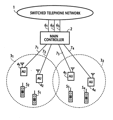
9Referring now to Fig. 1, there is shown a cordless key telephone
10 system according to the present invention. The system includes a main
11 controller 2 connected to the public or private telephone network 1 via
12 three subscriber lines 61 through 63, for example. Main controller 2 is
13 further connected by local lines 71~74 to access units 41~44 which are
14 divided into groups corresponding to service zones 31 and 32 and
15 located at strategic points of the corresponding service zones. The
16 system has four cordless stations 51 through 54, for example, which may
17 roam across the boundaries between service zones 31 and 32. A two-
18 way control channel is provided between the access units and cordless
19 stations. During standby modes, all access units and cordless stations are
switched to the control channel to constantly monitor signals carried
21 thereon. During a call origination or termination phase, the control
22 channel is used to exchange control signals to assign a two-way speech
2 3 channel.
24 The frequency spectrum of the radio signals used in the system is
equally divided at 1 2.5-kHz intervals into 89 (eighty-nine) telephone
2 6 channels each with a bandwidth of 3 kHz. In order to avoid interference
27 between control signals and speech signals due to third-order
28 intermodulation distortion, service zone 31 is permanently assigned an
29 even-numbered control channel, say, channel #46 and a plurality of odd-
NE-354
205 1 086
- 6 -
numbered speech channels (channel #1 to channel #87), while zone 32 is
2 permanently assigned an odd-numbered control channel, say, channel
3 #89, and a plurality of even-numbered speech channels (channel #2 to
4 channel #88) with the exception of channel #46.
s As shown in Fig. 2, main controller 2 comprises line interfaces 81~83
6 respectively coupled via subscriber lines 61~63 to the network 1, local
7 interfaces 101~104 respectively coupled to local lines 71~74, and a
8 switching matrix 9 for establishing a connection between the interfaces 8
9 and 10. A control circuit 11 is coupled to all interfaces 8 and 10 to supply
a switching control signal to matrix 9. An announcement source 1 lA is
11 connected to all line interfaces 8 to supply a melodious tone and voiced
12 announcement when an exchange line is kept in a line-hold condition in a
13 manner as will be described. Control circuit 11 is connected to a call
14 status memory 11 B in which relationships between calls, exchange lines,
access units and cordless stations are stored. Using the contents of call
16 status memory 11 B, control circuit 11 controls the switching matrix 9.
17 As illustrated in Fig. 3, each access unit 4k includes a hybrid 12 having
18 its two-wire circuit coupled to the associated local line 7k. The transmit
19 portion of the four-wire circuit is coupled to the input of a transmitter 13,
the receive portion of the four-wire circuit being coupled to the output of
21 a receiver 14. The output of transmitter 13 is coupled via a diplexer 15 to
22 an antenna 16 for transmission to cordless stations. Signals received by
23 antenna 16 from cordless stations are coupled by diplexer 15 to the input
24 of receiver 14 for transmission to main controller 2. A frequency
synthesizer is included in transmitter 13 and receiver 14 to receive control
26 signals transmitted on the control channel from both sides of the access
27 unit for coupling to a control circuit 17. In a manner to be described,
2 8 control circuit 1 7 processes the received control signals for transmission to
29 either side of the unit using a channel memory 18 in which the status of
NE-354
205 1 086
- 7 -
the control channel of the own zone and the status of all speech channels
2 of the zone are stored. Each alert signal contains a system identifier and
3 a cordless-station identifier. The frequency synthesizers of access units 41
4 and 42 are tuned to channel #46 during standby mode readying to
receive signals and those of access units 43 and 44 are tuned to channel
6 #89 during standby mode.
7 In Fig. 4, signal from the nearby access unit is detected by an antenna
8 19 of each cordless station Sk and passed through a diplexer 20 to a
g receiver 21 where it is converted to an audio-frequency signal and
applied through a normally open switching circuit 22 to an earphone 23.
11 Signal from microphone 24 is coupled through switching circuit 22 to a
12 transmitter 25 where it is converted to a high-frequency signal and
13 applied through diplexer 20 to antenna 19. A field intensity detector 26 is
14 connected to receiver 21 to compare the field intensity of the cordless
15 station with a prescribed threshold and applies an output signal to a
16 control circuit 27 if the field intensity is higher than the threshold. As will
17 be described, control circuit 27 exchanges control signals with receiver 21
18 and transmitter 25 by successively tuning their frequency synthesizers to
19 specified control channels and switching to an idle speech channel when
20 it is assigned by the communicating access unit. A tone ringer 28 is
21 connected to control circuit 27 to audibly alert the user upon receipt of an
22 incoming call from the network. A keypad 29 is also connected to control
23 circuit 27 to generate an off-hook signal when answering an incoming call
24 or generate a call request as well as destination address information when
25 originating an outgoing call.
26 Each of the respective control circuits of main controller 2, access units
27 4 and cordless stations 5 is a microprocessor-based controller which is
28 programmed to perform a stored sequence of instructions as described
2 9 hereinbelow.
NE-354
-
205 1 086
- 8 -
FLOWCHARTS OF THE FIRST EMBODIMENT
2 A first embodiment of the present invention will now be described
3 with reference to flowcharts shown in Figs. 5 to 7.
4 In Fig. 5, during a talking mode with a distant station via an exchange
S line the program execution of the controller 27 of a cordless station starts
6 with decision step 30 to check the output of field intensity detector 26 to
7 see if the field intensity is lower than an acceptable level. If this is the
8 case, detector 26 generates an output and the program branches at step
9 30 to step 31 to switch the cordless station to the other control channel of
the system to transmit a zone switching signal identifying the cordless
11 station. The program proceeds to step 32 to switch the cordless station
12 to the other control channel of the system, i.e., the control channel of a
13 second zone to which the cordless station is about to enter, and moves
14 ahead to step 33 to wait for an alert signal. If the system has three or
more control channels assigned respectively to different zones, control
16 channels of other zones may be scanned to detect one having highest
17 intensity as the control channel of the second zone and the zone
18 switching signal may further contain an identifier indicating the control
19 channel of the second zone.
As will be described, this zone switching signal is received by the
21 access unit of a first zone and relayed to main controller 2. On receiving22 this zone switching signal, main controller 2 returns a disconnect signal to
2 3 the access unit of the first zone, and then transmits an alert signal to one
24 of the access units of a second zone.
The alert signal is relayed from the access unit,of the second zone to
2 6 the cordless station in which it is detected at step 33. The program
27 branches at step 33 to step 34 to transmit an acknowledgment (ACK)
2 8 signal to the new access unit.
29 On receiving this ACK signal, the access unit of the second zone
NE-354
2~ ~ 0
g
returns a channel assignment signal to the cordless station, containing a
2 channel identifier indicating a speech channel and the identifier of that
3 cordless station to which the speech channel is to be assigned.
4 The program proceeds to step 35 to check to see if a channel
5 assignment signal is received. If this signal is not received within a
6 specified period, control returns to step 34 to retransmit the
7 acknowledgment signal. On receiving a channel assignment signal, the
8 program branches at step 35 to step 36 to switch the cordless station to
9 the assigned speech channel and transmits a switching complete signal to
10 the access unit of the second zone (step 37).
1 1 The switching complete signal is relayed by the access unit of the
12 second zone to the main controller to cause it to transmit a turn-on signal.13 Control advances to step 38 to wait for the turn-on signal. If this turn-14 on signal is not received within a specified period, control returns to step15 37 to retransmit the switching complete signal. On receiving this turn-on
16 signal, cordless station operates switch 22 to reestablish a connection
17 through the access unit to the main controller.
18 In Fig. 6A, with a connection being established between a cordless
1 9 station and an exchange line the program execution of the access unit 4
that is involved in the connection begins with decision step 40 to check for
21 the presence of a zone switching signal from the cordless station. If the
22 answer is affirmative, the program branches at step 40 to step 41 to relay
23 the received zone switching signal to main controller 2 and goes to step
24 42 to wait for a disconnect signal from the main controller.
As will be described, main controller 2 responds to the zone
26 switching signal by returning a disconnect signal to the access unit of the
27 first zone. On receiving it, the program at the access unit branches at step28 42 to step 43 to clear the connection to the cordless station, leaving the
29 access unit in a standby state.
NE-354
lo- 205 1 086
In Fig. 6B, when an access unit is in a standby state, the program
2 execution starts with decision step 44 to check for the reception of an alert3 signal from the main controller. This alert signal contains the identifier of4 the cordless station crossing a zone boundary. If there is one, control
s branches at step 44 to step 45 to broadcast the alert signal, and goes to
6 step 46 to wait for an acknowledgment signal returning from the
7 addressed cordless station. This alert signal will be received by that
8 cordless station and an acknowledgment signal will be returned
g therefrom. If the acknowledgment signal is not returned within a specified
10 period, control branches to step 45 to rebroadcast the alert signal.
11 On receiving the acknowledgment signal, the program branches at
12 step 46 to step 47 to relay the acknowledgment signal to the main
13 controller and proceeds to step 48 to scan all speech channels to select
14 an idle channel and broadcast a channel assignment signal identifying the
15 cordless station to which the selected idle speech channel is to be
16 assigned and the identifier of the selected channel. Control exits to step
17 49 to wait for a switching complete signal returning from the cordless
18 station.
19 The cordless station will respond to the channel assignment signal
from the access unit by reestablishing a link to the assigned speech
21 channel and returning a switching complete signal to the access unit. If
22 the switching complete signal is not received within a specified period, the
23 program branches at step 49 to step 48 to repeat the transmission of the
2 4 channel assignment signal.
In response to receipt of a switching complete,signal, the program at
2 6 the access unit branches at step 49 to step 50 to relay it to the main
27 controller and moves to step 51 to wait for a turn-on signal from the main
2 8 controller.
29 The program of the access unit now branches to step 52 to broadcast
NE-354
205 1 086
- 11
the received turn-on signal to all cordless stations so that the cordless
2 station entering the second zone is allowed to establish a speech path to
3 enter a talking mode again with the exchange line.
4 In Fig. 7, when a cordless station is in a talking mode through an
exchange line, the program execution of main controller 2 begins with
6 decision step 60 to check for the presence of a zone switching signal from7 the access unit through which the talking connection has been
8 established. If there is one, control branches at step 60 to step 61 to hold
9 the exchange line which is identified by a record in the call status
memory 11 B as corresponding to the cordless station from which the
11 zone switching signal has been received, and applies a musical tone or a
12 vocal announcement to the exchange line, indicating to the distant user
13 that the key-telephone user is now crossing a zone boundary and the
14 connection will be briefly interrupted. Exit then is to step 62 to return a
15 disconnect signal to the access unit to allow it to clear the connection-with16 the cordless telephone. The program then proceeds to step 63 to select
17 one of the access units of the second zone and transmit an alert signal to
18 the selected access unit. Exit then is to step 64 to check to see if an
19 acknowledgment signal is received from the access unit of the second
20 zone. If an acknowledgment signal is not received within a specified
21 period, step 63 is repeated to retransmit the alert signal. If the answer is
2 2 affirmative in step 64, control branches to decision step 65 to wait for a
23 switching complete signal from the cordless station via the access unit. If
24 there is one, the program branches to step 66 to connect the exchange
2 5 line to the access unit of the second zone and proceeds to step 67 to
2 6 transmit a turn-on signal to the access unit.
27 OPERATION OF THE FIRST EMBODIMENT
2 8 The operation of the first embodiment of the system will now be
2 9 described with reference to the drawings described above together with
NE-354
- 12 205 1 0 ~6
Fig. 8. Assume that cordless station 51 is in a talking mode with exchange
2 line 61 by way of access unit 42 and is leaving zone 31 and entering
3 second zone 32. When a low field intensity condition is detected (step
4 30, Fig. 5), a zone switching signal is transmitted (step 31) from station 5
5 and received and relayed by access unit 42 (steps 40 and 41, Fig. 6A) to
6 main controller 2. Main controller 2 receives the zone switching signal
7 (step 60, Fig. 7) and determines from the contents of call status memory
8 11 B that exchange line 61 (step 61) is being connected to cordless station
9 51 and holds the line in an announcement mode and transmits a
1 0 disconnect signal to access unit 42 (step 62). On receiving this disconnect
1 1 signal, access unit 42 clears the connection to cordless station 51 (steps 42,
12 43, Fig. 6A). Following the transmission of the disconnect signal, main
13 controller 2 selects an access unit 43 and applies to it an alert signal
1 4 identifying cordless station 51 (step 63, Fig. 7). This alert signal is received
1 5 and broadcast by access unit 43 (steps 44, 45, Fig. 6B) and finally
16 received by cordless station 51 (step 33, Fig. 5). Cordless station 51
17 returns an ACK signal (step 34), which is received and relayed by access
1 8 unit 43 (step 47) to main controller 2 (step 64). Main controller 2
1 9 reconnects the exchange line 61 to access unit 43.
20 Meanwhile, access unit 43 scans the speech channels of zone 32 to
21 select an idle channel and broadcasts a channel assignment signal
22 identifying the selected channel and the cordless station 51 (step 48).
23 The channel assignment signal is received by cordless station 51 (step 35)
24 and cordless station 51 is switched to the assigned speech channel (step
25 36) to establish a connection between cordless station 51 and access unit
26 43. A switching complete signal is then transmitted from cordless station
27 51 (step 37) to access unit 43 and relayed to main controller 2 (steps 49,
2 8 50). Main controller 2 now connects the exchange line 61 to access unit
2 9 43 (step 66) and transmits a turn-on signal (step 67) to access unit 43,
NE-354
-
- 13 205 1 086
which, in turn, broadcasts it to cordless stations (steps 51, 52). Cordless
2 station 51 responds to this turn-on signal by activating switch 22 and
3 reestablishes the talking connection with the distant station via the
4 exchange line 61 (steps 38 and 39, Fig. 5).
s FLOWCHARTS OF THE SECOND EMBODIMENT
6 A second embodiment of the present invention will now be described
7 with reference to flowcharts shown in Figs. 9 to 11.
8 In Fig. 9, during a talking mode with an exchange line the program
9 execution of a cordless station starts with decision step 70 to check to see
10 if the field intensity is reduced to a level which indicates that the cordless
11 station is leaving a first zone in which the talking connection has been
12 established and entering a second zone. If the answer is affirmative,
13 program branches at step 70 to step 71 to switch the cordless station to
14 the control channel of the first zone and transmit a zone switching signal.
15 As will be described, the zone switching signal is received by the
16 access unit of the first zone and relayed to the main controller in which
17 the call status memory is accessed to detect an exchange line with which
18 the cordless station is in talking mode. The main controller keeps the
19 exchange line in an announcement-hold mode in a manner identical to
20 the first embodiment by coupling the announcement source 1 lA to the
21 line interface with which the exchange is connected.
22 Control then proceeds to step 72 to check to see if the control
2 3 channel of the second zone is idle. If the answer is affirmative, the
24 program branches at step 72 to step 73 to switch the cordless station to
2 5 the control channel of the second zone and transmit a call request signal
26 to one of the access units of the second zone which is selected by the
27 main controller, with the call request signal containing the cordless station2 8 identifier and the control channel identifier of the second zone. Control
2 9 moves ahead to step 74 to wait for a channel assignment signal.
NE-354
205 1 0~6
- 14-
As will be described, the call request signal from the cordless station is
2 relayed by the selected access unit to the main controller, whereupon it
3 returns a disconnect signal to the access unit of the first zone to allow it to
4 clear the connection to the cordless station. Meanwhile, the access unit of
s the second zone broadcasts a channel assignment signal.
6 On receiving the channel assignment signal, the program of the
7 cordless station branches at step 74 to step 75 to switch the station to an
8 idle speech channel specified by the channel assignment signal. The
g program then proceeds to step 76 to transmit a switching complete signal
10 to the access unit of the second zone, and goes to step 77 to wait for a
1 1 turn-on signal from the main controller via the access unit. When the
12 turn-on signal is received by the cordless station, the program branches
13 at step 77 to step 78 to turn on the speech circuit switch 22 to reestablish
14 the talking connection.
In Fig. 1 OA, with a connection being established between a cordless
16 station and an exchange line the program execution of the access unit
17 that is involved in the connection begins with decision step 80 to check for
18 the presence of a zone switching signal from the cordless station. If the
19 answer is affirmative, the program branches at step 80 to step 81 to relay
the received zone switching signal to main controller 2 and goes to step
21 82 to wait for a disconnect signal from the main controller. On receiving
22 the disconnect signal, the program branches at step 82 to step 83 to clear
2 3 the connection to the cordless station, leaving the access unit in a standby
2 4 state.
In Fig. 1 OB, when an access unit is in a standby mode, the program
2 6 execution starts with decision step 84 to check for the reception of a call
27 request signal from a cordless station. If there is one, control branches at
28 step 84 to step 85 to broadcast the relay the call request signal to the
29 main controller, and goes to step 86 to scan all speech channels to select
NE-354
-
-lS- 2051086
an idle channel and broadcast a channel assignment signal identifying the
2 cordless station to which the selected idle speech channel is to be
3 assigned and the selected channel identifier. Control exits to step 87 to
4 wait for a switching complete signal from the cordless station. On
s receiving it, control branches to step 88 to relays it to the main controller
6 and goes to decision step 89 to check for the reception of a turn-on signal
7 from the main controller. When this signal is received, the program
8 branches at step 89 to step 90 to broadcast the turn-on signal to cordless
9 stations.
10 In Fig. 11, when a cordless station is in a talking mode through an
11 exchange line, the program execution of main controller 2 begins with
12 decision step 100 to check for the presence of a zone switching signal
13 from the access unit through which the talking connection has been
14 established. If there is one, control branches at step 100 to step 101 to
15 hold the exchange line which is identified by the call status memory of
16 controller 11 as corresponding to the cordless station from which the
17 zone switching signal has been received, and applies a musical tone or a
18 vocal announcement to the exchange line, indicating to the distant user
19 that the key-telephone user is now leaving a first zone and entering a
20 second zone and the connection will be briefly interrupted. Exit then is to
21 decision step 102 to wait for a call request signal from the cordless station2 2 by way of an access unit of the second zone. On receiving the call
23 request signal, the program branches at step 102 to step 103 to transmit a
24 disconnect signal to the access unit of the first zone to allow it to clear the
2 5 connection with the cordless station which has left the first zone. Exit then
2 6 is to step 104 to check to see if a switching complete signal is received
27 from the access unit of the second zone. If the answer is affirmative in
28 step 104, control branches to step 105 to connect the exchange line to
2 9 the access unit and exits to step 106 to transmit a turn-on signal to the
NE-354
-16- 205 1 086
access unit of the second zone.
2 OPERATION OF THE SECOND EMBODIMENT
3 The operation of the second embodiment of the system will now be
4 described with reference to Figs. 9-12. As in the case of the first
S embodiment, it is assumed that cordless station 51 is in a talking mode
6 with exchange line 61 by way of access unit 42 and is leaving first zone 31
7 and entering second zone 32. When a low field intensity condition is
8 detected (step 70, Fig. 9), a zone switching signal is transmitted (step 71)
g from station 51 and received and relayed by access unit 42 (steps 80 and
1 0 81, Fig. 1 OA) to main controller 2. Main controller 2 receives the zone
1 1 switching signal (step 100, Fig. 11) and determines from the call status
1 2 memory of controller 11 that exchange line 61 (step 101) is being
13 connected to cordless station 51 and holds the line in an announcement
1 4 mode. When cordless station 51 has entered the second zone, the field
1 s intensity of the control channel of the second zone detected by the
16 station will become higher than a specified level (step 72) and a call
17 request signal is sent from cordless station 51 to access unit 43 (step 73).
1 8 The call request signal is relayed by access unit 43 (steps 84, 85, Fig. 1 OB)
1 9 to the main controller, whereupon it proceeds to transmit a disconnect
2 0 signal to access unit 42 (steps 102 and 103, Fig. 11). On receiving this
21 disconnect signal, access unit 42 clears the connection to cordless station
22 51 (steps 82, 83, Fig. 10A).
2 3 Meanwhile, access unit 43 responds to the call request signal from
24 station 51 by scanning speech channels of the second zone and selects
25 one of the idle channels and broadcasts a channel,assignment signal.
26 Cordless station 51 receives this signal (step 74) and switches to the
27 assigned speech channel (step 75). A switching complete signal is then
2 8 transmitted from cordless station 51 to access unit 43 (step 76) and
2 9 relayed to main controller 2 (steps 87, 88). In response to the switching
NE-354
- 17- 205 1 086
complete signal (step 104), main controller 2 connects the exchange line
2 61 to access unit 43 (step 105) and transmits a turn-on signal (step 106) to
3 access unit 43, which, in turn, broadcasts it to cordless stations (steps 89,
4 90). Cordless station 51 responds to this turn-on signal by activating
S switch 22 and reestablishes the talking connection with the distant station
6 via the exchange line 61 (steps 77, 78, Fig. 9).