Language selection

Search

Patent 2051188 Summary

Third-party information liability

Some of the information on this Web page has been provided by external sources. The Government of Canada is not responsible for the accuracy, reliability or currency of the information supplied by external sources. Users wishing to rely upon this information should consult directly with the source of the information. Content provided by external sources is not subject to official languages, privacy and accessibility requirements.

Claims and Abstract availability

Any discrepancies in the text and image of the Claims and Abstract are due to differing posting times. Text of the Claims and Abstract are posted:

  • At the time the application is open to public inspection;
  • At the time of issue of the patent (grant).
(12) Patent: (11) CA 2051188
(54) English Title: FUSE BOX FOR BLADE-TYPE FUSE
(54) French Title: BOITE A FUSIBLES POUR FUSIBLES DU TYPE A LAME
Status: Expired and beyond the Period of Reversal
Bibliographic Data
(51) International Patent Classification (IPC):
  • H01H 85/153 (2006.01)
  • H01H 85/20 (2006.01)
(72) Inventors :
  • ARAKI, MAMORU (Japan)
  • SUGIYAMA, MASAAKI (Japan)
(73) Owners :
  • YAZAKI CORPORATION
(71) Applicants :
  • YAZAKI CORPORATION (Japan)
(74) Agent: ROBIC AGENCE PI S.E.C./ROBIC IP AGENCY LP
(74) Associate agent:
(45) Issued: 1996-05-28
(22) Filed Date: 1991-09-11
(41) Open to Public Inspection: 1992-03-13
Examination requested: 1991-09-11
Availability of licence: N/A
Dedicated to the Public: N/A
(25) Language of filing: English

Patent Cooperation Treaty (PCT): No

(30) Application Priority Data:
Application No. Country/Territory Date
2-95099 (Japan) 1990-09-12

Abstracts

English Abstract


A fuse box has a fuse cavity for receiving the
body of a blade type fuse having blade-like male terminals
projecting from the body into an insertion direction of the
blade type fuse. The body of blade type fuse has opposed
ends extending into the insertion direction and a side rib
provided on each of the opposed ends and extending into the
insertion direction. The fuse cavity has opposed walls for
receiving therebetween the opposed ends of the blade type
fuse when the blade type fuse is inserted. The fuse cavity
also has two pairs of second ribs on the opposed walls, each
pair being positioned to define a receiving groove there-
between for receiving the side rib of the blade type fuse.


Claims

Note: Claims are shown in the official language in which they were submitted.

What is claimed is:
1. A fuse box comprising a fuse cavity for receiving a
body of a blade type fuse having blade-like male terminals
projecting from the body into an insertion direction of the
blade type fuse, the body having opposed ends extending into
said insertion direction and a first rib provided on each of
the opposed ends, said first rib extending into the
insertion direction, wherein said fuse cavity including:
opposed walls between which said opposed ends of
said body of the blade type fuse are received when said
blade type fuse is inserted; and
two pairs of second ribs provided on said opposed
walls, each pair being positioned to define a receiving
groove therebetween for receiving said first rib of said
blade type fuse.
2. A fuse box according to Claim 1, wherein each of said
second ribs has a beveled guiding surface so that said first
rib of said blade type fuse is guided into said receiving
groove when said blade type fuse is inserted into said fuse
cavity.
3. A fuse box according to Claim 2, wherein each of said
two pairs including two ribs, each of said two ribs being
positioned in opposing relation on each of said opposite
walls.

4. A fuse box according to claim 2, wherein said fuse box
further includes receptacle cavities provided adjacent said
fuse cavity, said receptacle cavities housing receptacles
therein for mating said blade-like male terminals of said
blade type fuse when said blade type fuse is inserted into
said fuse cavity.

Description

Note: Descriptions are shown in the official language in which they were submitted.


205 1 1 88
The present invention relates to improvement of a
fuse box installed on vehicles such as automobiles.
A conventional on-vehicle fuse box has a matrix of
fuse receiving walls. Such a receiving wall defines a fuse
cavity for receiving a blade type fuse and a receptacle
cavity for accommodating a double receptacle. The double
receptacle has two female type electrical contacts in one
piece construction. The first contact receives a male
terminal of a bus bar upwardly projecting from the bottom of
the fuse box while the second contact receives a male
contact of the blade type fuse.
The second contact has inwardly folded resilient
contacts between which the male terminal of the blade type
fuse is inserted. The double receptacle is housed in the
receptacle cavity with clearances between the inner wall of
the receptacle cavity, so that the second contact is allowed
to displace outwardly of resilient contact to relieve the
double receptacle of excessive mechanical strain. However,
the blade type fuse is sometimes inadvertently wrongly
inserted into the corresponding clearance, in which case the
blades are deformed allowing further insertion of the head
portion of the blade type fuse into the fuse cavity. The
head goes into the cavity while being in normal attitude.
It is difficult to determine by appearance whether the fuse
is normally inserted or wrongly inserted. This wrong
insertion of blade type fuse is a source of abnormal heat
generation at the contacts.

2gSl 188
SUMMARY OF THE INVENTION
The present invention was made in view of the
aforementioned drawbacks and an object of the invention is
to provide a fuse box in which wrong insertion of blade type
fuse is effectively prevented.
According to the present invention there is
provided a fuse box comprising a fuse cavity for receiving
a body of a blade type fuse having blade-like male terminals
projecting from the body into an insertion direction of the
blade type fuse, the body having opposed ends extending into
said insertion direction and a first rib provided on each of
the opposed ends, said first rib extending into the
insertion direction, wherein said fuse cavity including:
opposed walls between which said opposed ends of
said body of the blade type fuse are received when said
blade type fuse is inserted; and
two pairs of second ribs provided on said opposed
walls, each pair being positioned to define a receiving
groove therebetween for receiving said first rib of said
blade type fuse.
Preferably, each of said second ribs has a beveled
guiding surface so that the first rib of the blade type fuse
is guided into the receiving groove when the blade type fuse
is inserted into the fuse cavity.
Preferably, each of the two pairs include two
ribs, each of the two ribs being positioned in opposing
relation on each of said opposite walls.
, .~

-
2 0 5 1 1 8 8
The fuse box may further include receptacle
cavities provided adjacent the fuse cavity, the receptacle
cavities housing receptacles therein for mating the blade-
like male terminals of the blade type fuse when the blade
type fuse is inserted into the fuse cavity.
BRIEF DESCRIPTION OF THE DRAWINGS
Features and other objects of the invention will
be more apparent from the description of the preferred
embodiment with reference to the accompanying drawings in
which:
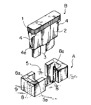
Fig. 1 is a perspective view of an embodiment of
the present invention;
Fig. 2 is a cross-sectional view of Fig. 1,
showing essential part of a fuse box when a blade type fuse
is inserted;
Fig. 3 is another cross-sectional view of Fig. 1
when the blade type fuse is inserted in a wrong direction;
Fig. 4 is a perspective view of a conventional
fuse box and a blade type fuse;
Fig. 5 is a cross-sectional view showing essential
part of the conventional fuse box when a blade type fuse is
inserted.
DETAILED DESCRIPTION OF THE PREFERRED EMBODIMENT
Referring to Figs. 1 and 2, a blade type fuse B
has a substantially plate like body 2 having a head 1 on the
,.. ~

205 ~ 1 88
top thereof and two blade like male terminals 3 and 3
projecting downwardly from the body 2. Within the body 2 is
connected a fuse element (not shown) between the terminals
3 and 3. The body 2 has at its lateral ends ribs 4 and 4
that extend in the direction in which the blade type fuse is
inserted. The respective rib 4 has a beveled guide surface
4a at its forward end for properly guiding the fuse into a
fuse cavity 5a of a fuse box.
The fuse box has a matrix of fuse receiving walls.
Fig. 1 shows one such receiving wall 5 that forms a fuse
cavity 5a for receiving the plate like body 2 of blade type
fuse B. The fuse cavity 5a has a rectangular opening into
which the plate like body is inserted. Below the fuse
cavity 5a is provided a double receptacle cavity 5b that
receives a double receptacle 6. The double receptacle has
inwardly folded resilient contacts 6b between which the male
terminal 3 of the blade type fuse B is inserted, and
resilient contacts 6a between which the male terminal 7a of
a bus bar 7 is inserted. The double receptacle 6 is housed
in the receptacle cavity 5b with some clearance between the
inner wall of the receptacle cavity 5b.
The fuse cavity 5a is formed with a pair of wrong
insertion detecting ribs 8 and 8 at each longitudinal end of
the fuse cavity 5a. The wrong insertion detecting ribs 8
are positioned in opposing relation with each other so as to
define a receiving groove 9 therebetween. Each rib has a
beveled guiding surface 8a so that the rib 4 of the blade
type fuse is guided into the groove 9 when inserted into the
fuse cavity.

205 1 1 88
When the blade type fuse B is inserted into the
fuse cavity 5a, the rib 4 of blade type fuse B is guided by
the beveled guiding surface 8a and 8a into the groove 9.
The male terminal 3 is guided toward the contact 6b of
double receptacles 6. If the tip of the male terminal 3 is
wrongly inserted, the beveled guiding surface 8a of wrong
insertion detecting rib 8 blocks the beveled guide surface
4a of blade type fuse preventing further insertion of the
fuse. Then, the head 1 of the blade type fuse projects
outwardly of the opening of fuse cavity 5a as shown in Fig.
3.
If we refer to the prior art, Figs. 4 and 5 show
a receiving wall a that defines a fuse cavity b for
receiving a blade type fuse and a receptacle cavity bl for
accommodating a double receptacle c. The double receptacle
c has female type electrical contacts cl and c2 in one piece
construction. The contact cl receives a male terminal dl of
a bus bar d upwardly projecting from the bottom of the fuse
box while the contact c2 receives a male contact el of the
blade type fuse e.
The contact c2 has inwardly folded resilient
contacts c' and c" between which the male terminal el of the
blade type fuse e is inserted. The double receptacle c is
housed in the receptacle cavity bl with clearances f and f'
between the inner wall of the receptacle cavity bl, so that
the contact c2 is allowed to displace outwardly of resilient
contact c" to relieve the double receptacle c of excessive
mechanical strain. However, the blade type fuse e is
sometimes inadvertently wrongly inserted into the clearance

-
205 1 1 88
f, in which case the blades el are deformed as shown in Fig.
4 allowing further insertion of head portion e2 of the blade
type fuse e into the fuse cavity b. The head goes into the
cavity while being in normal attitude. It is difficult to
determine by appearance whether the fuse is normally
inserted or wrongly inserted.

Representative Drawing
A single figure which represents the drawing illustrating the invention.
Administrative Status

2024-08-01:As part of the Next Generation Patents (NGP) transition, the Canadian Patents Database (CPD) now contains a more detailed Event History, which replicates the Event Log of our new back-office solution.

Please note that "Inactive:" events refers to events no longer in use in our new back-office solution.

For a clearer understanding of the status of the application/patent presented on this page, the site Disclaimer , as well as the definitions for Patent , Event History , Maintenance Fee  and Payment History  should be consulted.

Event History

Description Date
Time Limit for Reversal Expired 2010-09-13
Letter Sent 2009-09-11
Inactive: IPC from MCD 2006-03-11
Grant by Issuance 1996-05-28
Application Published (Open to Public Inspection) 1992-03-13
All Requirements for Examination Determined Compliant 1991-09-11
Request for Examination Requirements Determined Compliant 1991-09-11

Abandonment History

There is no abandonment history.

Fee History

Fee Type Anniversary Year Due Date Paid Date
MF (patent, 6th anniv.) - standard 1997-09-11 1997-08-07
MF (patent, 7th anniv.) - standard 1998-09-11 1998-08-05
MF (patent, 8th anniv.) - standard 1999-09-13 1999-07-20
MF (patent, 9th anniv.) - standard 2000-09-11 2000-08-16
MF (patent, 10th anniv.) - standard 2001-09-11 2001-08-17
MF (patent, 11th anniv.) - standard 2002-09-11 2002-08-16
MF (patent, 12th anniv.) - standard 2003-09-11 2003-08-21
MF (patent, 13th anniv.) - standard 2004-09-13 2004-08-19
MF (patent, 14th anniv.) - standard 2005-09-12 2005-08-05
MF (patent, 15th anniv.) - standard 2006-09-11 2006-08-08
MF (patent, 16th anniv.) - standard 2007-09-11 2007-08-08
MF (patent, 17th anniv.) - standard 2008-09-11 2008-08-11
Owners on Record

Note: Records showing the ownership history in alphabetical order.

Current Owners on Record
YAZAKI CORPORATION
Past Owners on Record
MAMORU ARAKI
MASAAKI SUGIYAMA
Past Owners that do not appear in the "Owners on Record" listing will appear in other documentation within the application.
Documents

To view selected files, please enter reCAPTCHA code :


To view images, click a link in the Document Description column. To download the documents, select one or more checkboxes in the first column and then click the "Download Selected in PDF format (Zip Archive)" or the "Download Selected as Single PDF" button.

List of published and non-published patent-specific documents on the CPD .

If you have any difficulty accessing content, you can call the Client Service Centre at 1-866-997-1936 or send them an e-mail at CIPO Client Service Centre.


Document
Description 
Date
(yyyy-mm-dd) 
Number of pages   Size of Image (KB) 
Description 1996-05-27 6 200
Abstract 1996-05-27 1 21
Claims 1996-05-27 2 40
Drawings 1996-05-27 2 47
Abstract 1994-03-25 1 21
Drawings 1994-03-25 2 52
Claims 1994-03-25 2 41
Description 1994-03-25 5 149
Representative drawing 1999-07-07 1 11
Maintenance Fee Notice 2009-10-25 1 170
Fees 1998-08-04 1 39
Fees 1997-08-06 1 44
Fees 1999-07-19 1 32
Fees 1994-08-18 1 43
Fees 1996-08-05 1 44
Fees 1993-08-09 1 41
Fees 1995-08-22 1 40
Examiner Requisition 1994-01-27 2 64
Prosecution correspondence 1994-07-25 2 56
Examiner Requisition 1995-08-17 1 58
Prosecution correspondence 1995-12-10 2 44
PCT Correspondence 1996-03-17 1 30
Courtesy - Office Letter 1992-05-19 1 39