Sélection de la langue

Search

Sommaire du brevet 2051188 

Énoncé de désistement de responsabilité concernant l'information provenant de tiers

Une partie des informations de ce site Web a été fournie par des sources externes. Le gouvernement du Canada n'assume aucune responsabilité concernant la précision, l'actualité ou la fiabilité des informations fournies par les sources externes. Les utilisateurs qui désirent employer cette information devraient consulter directement la source des informations. Le contenu fourni par les sources externes n'est pas assujetti aux exigences sur les langues officielles, la protection des renseignements personnels et l'accessibilité.

Disponibilité de l'Abrégé et des Revendications

L'apparition de différences dans le texte et l'image des Revendications et de l'Abrégé dépend du moment auquel le document est publié. Les textes des Revendications et de l'Abrégé sont affichés :

  • lorsque la demande peut être examinée par le public;
  • lorsque le brevet est émis (délivrance).
(12) Brevet: (11) CA 2051188
(54) Titre français: BOITE A FUSIBLES POUR FUSIBLES DU TYPE A LAME
(54) Titre anglais: FUSE BOX FOR BLADE-TYPE FUSE
Statut: Périmé et au-delà du délai pour l’annulation
Données bibliographiques
(51) Classification internationale des brevets (CIB):
  • H01H 85/153 (2006.01)
  • H01H 85/20 (2006.01)
(72) Inventeurs :
  • ARAKI, MAMORU (Japon)
  • SUGIYAMA, MASAAKI (Japon)
(73) Titulaires :
  • YAZAKI CORPORATION
(71) Demandeurs :
  • YAZAKI CORPORATION (Japon)
(74) Agent: ROBIC AGENCE PI S.E.C./ROBIC IP AGENCY LP
(74) Co-agent:
(45) Délivré: 1996-05-28
(22) Date de dépôt: 1991-09-11
(41) Mise à la disponibilité du public: 1992-03-13
Requête d'examen: 1991-09-11
Licence disponible: S.O.
Cédé au domaine public: S.O.
(25) Langue des documents déposés: Anglais

Traité de coopération en matière de brevets (PCT): Non

(30) Données de priorité de la demande:
Numéro de la demande Pays / territoire Date
2-95099 (Japon) 1990-09-12

Abrégés

Abrégé anglais


A fuse box has a fuse cavity for receiving the
body of a blade type fuse having blade-like male terminals
projecting from the body into an insertion direction of the
blade type fuse. The body of blade type fuse has opposed
ends extending into the insertion direction and a side rib
provided on each of the opposed ends and extending into the
insertion direction. The fuse cavity has opposed walls for
receiving therebetween the opposed ends of the blade type
fuse when the blade type fuse is inserted. The fuse cavity
also has two pairs of second ribs on the opposed walls, each
pair being positioned to define a receiving groove there-
between for receiving the side rib of the blade type fuse.

Revendications

Note : Les revendications sont présentées dans la langue officielle dans laquelle elles ont été soumises.


What is claimed is:
1. A fuse box comprising a fuse cavity for receiving a
body of a blade type fuse having blade-like male terminals
projecting from the body into an insertion direction of the
blade type fuse, the body having opposed ends extending into
said insertion direction and a first rib provided on each of
the opposed ends, said first rib extending into the
insertion direction, wherein said fuse cavity including:
opposed walls between which said opposed ends of
said body of the blade type fuse are received when said
blade type fuse is inserted; and
two pairs of second ribs provided on said opposed
walls, each pair being positioned to define a receiving
groove therebetween for receiving said first rib of said
blade type fuse.
2. A fuse box according to Claim 1, wherein each of said
second ribs has a beveled guiding surface so that said first
rib of said blade type fuse is guided into said receiving
groove when said blade type fuse is inserted into said fuse
cavity.
3. A fuse box according to Claim 2, wherein each of said
two pairs including two ribs, each of said two ribs being
positioned in opposing relation on each of said opposite
walls.

4. A fuse box according to claim 2, wherein said fuse box
further includes receptacle cavities provided adjacent said
fuse cavity, said receptacle cavities housing receptacles
therein for mating said blade-like male terminals of said
blade type fuse when said blade type fuse is inserted into
said fuse cavity.

Description

Note : Les descriptions sont présentées dans la langue officielle dans laquelle elles ont été soumises.

205 1 1 88
The present invention relates to improvement of a
fuse box installed on vehicles such as automobiles.
A conventional on-vehicle fuse box has a matrix of
fuse receiving walls. Such a receiving wall defines a fuse
cavity for receiving a blade type fuse and a receptacle
cavity for accommodating a double receptacle. The double
receptacle has two female type electrical contacts in one
piece construction. The first contact receives a male
terminal of a bus bar upwardly projecting from the bottom of
the fuse box while the second contact receives a male
contact of the blade type fuse.
The second contact has inwardly folded resilient
contacts between which the male terminal of the blade type
fuse is inserted. The double receptacle is housed in the
receptacle cavity with clearances between the inner wall of
the receptacle cavity, so that the second contact is allowed
to displace outwardly of resilient contact to relieve the
double receptacle of excessive mechanical strain. However,
the blade type fuse is sometimes inadvertently wrongly
inserted into the corresponding clearance, in which case the
blades are deformed allowing further insertion of the head
portion of the blade type fuse into the fuse cavity. The
head goes into the cavity while being in normal attitude.
It is difficult to determine by appearance whether the fuse
is normally inserted or wrongly inserted. This wrong
insertion of blade type fuse is a source of abnormal heat
generation at the contacts.

2gSl 188
SUMMARY OF THE INVENTION
The present invention was made in view of the
aforementioned drawbacks and an object of the invention is
to provide a fuse box in which wrong insertion of blade type
fuse is effectively prevented.
According to the present invention there is
provided a fuse box comprising a fuse cavity for receiving
a body of a blade type fuse having blade-like male terminals
projecting from the body into an insertion direction of the
blade type fuse, the body having opposed ends extending into
said insertion direction and a first rib provided on each of
the opposed ends, said first rib extending into the
insertion direction, wherein said fuse cavity including:
opposed walls between which said opposed ends of
said body of the blade type fuse are received when said
blade type fuse is inserted; and
two pairs of second ribs provided on said opposed
walls, each pair being positioned to define a receiving
groove therebetween for receiving said first rib of said
blade type fuse.
Preferably, each of said second ribs has a beveled
guiding surface so that the first rib of the blade type fuse
is guided into the receiving groove when the blade type fuse
is inserted into the fuse cavity.
Preferably, each of the two pairs include two
ribs, each of the two ribs being positioned in opposing
relation on each of said opposite walls.
, .~

-
2 0 5 1 1 8 8
The fuse box may further include receptacle
cavities provided adjacent the fuse cavity, the receptacle
cavities housing receptacles therein for mating the blade-
like male terminals of the blade type fuse when the blade
type fuse is inserted into the fuse cavity.
BRIEF DESCRIPTION OF THE DRAWINGS
Features and other objects of the invention will
be more apparent from the description of the preferred
embodiment with reference to the accompanying drawings in
which:
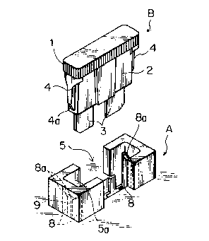
Fig. 1 is a perspective view of an embodiment of
the present invention;
Fig. 2 is a cross-sectional view of Fig. 1,
showing essential part of a fuse box when a blade type fuse
is inserted;
Fig. 3 is another cross-sectional view of Fig. 1
when the blade type fuse is inserted in a wrong direction;
Fig. 4 is a perspective view of a conventional
fuse box and a blade type fuse;
Fig. 5 is a cross-sectional view showing essential
part of the conventional fuse box when a blade type fuse is
inserted.
DETAILED DESCRIPTION OF THE PREFERRED EMBODIMENT
Referring to Figs. 1 and 2, a blade type fuse B
has a substantially plate like body 2 having a head 1 on the
,.. ~

205 ~ 1 88
top thereof and two blade like male terminals 3 and 3
projecting downwardly from the body 2. Within the body 2 is
connected a fuse element (not shown) between the terminals
3 and 3. The body 2 has at its lateral ends ribs 4 and 4
that extend in the direction in which the blade type fuse is
inserted. The respective rib 4 has a beveled guide surface
4a at its forward end for properly guiding the fuse into a
fuse cavity 5a of a fuse box.
The fuse box has a matrix of fuse receiving walls.
Fig. 1 shows one such receiving wall 5 that forms a fuse
cavity 5a for receiving the plate like body 2 of blade type
fuse B. The fuse cavity 5a has a rectangular opening into
which the plate like body is inserted. Below the fuse
cavity 5a is provided a double receptacle cavity 5b that
receives a double receptacle 6. The double receptacle has
inwardly folded resilient contacts 6b between which the male
terminal 3 of the blade type fuse B is inserted, and
resilient contacts 6a between which the male terminal 7a of
a bus bar 7 is inserted. The double receptacle 6 is housed
in the receptacle cavity 5b with some clearance between the
inner wall of the receptacle cavity 5b.
The fuse cavity 5a is formed with a pair of wrong
insertion detecting ribs 8 and 8 at each longitudinal end of
the fuse cavity 5a. The wrong insertion detecting ribs 8
are positioned in opposing relation with each other so as to
define a receiving groove 9 therebetween. Each rib has a
beveled guiding surface 8a so that the rib 4 of the blade
type fuse is guided into the groove 9 when inserted into the
fuse cavity.

205 1 1 88
When the blade type fuse B is inserted into the
fuse cavity 5a, the rib 4 of blade type fuse B is guided by
the beveled guiding surface 8a and 8a into the groove 9.
The male terminal 3 is guided toward the contact 6b of
double receptacles 6. If the tip of the male terminal 3 is
wrongly inserted, the beveled guiding surface 8a of wrong
insertion detecting rib 8 blocks the beveled guide surface
4a of blade type fuse preventing further insertion of the
fuse. Then, the head 1 of the blade type fuse projects
outwardly of the opening of fuse cavity 5a as shown in Fig.
3.
If we refer to the prior art, Figs. 4 and 5 show
a receiving wall a that defines a fuse cavity b for
receiving a blade type fuse and a receptacle cavity bl for
accommodating a double receptacle c. The double receptacle
c has female type electrical contacts cl and c2 in one piece
construction. The contact cl receives a male terminal dl of
a bus bar d upwardly projecting from the bottom of the fuse
box while the contact c2 receives a male contact el of the
blade type fuse e.
The contact c2 has inwardly folded resilient
contacts c' and c" between which the male terminal el of the
blade type fuse e is inserted. The double receptacle c is
housed in the receptacle cavity bl with clearances f and f'
between the inner wall of the receptacle cavity bl, so that
the contact c2 is allowed to displace outwardly of resilient
contact c" to relieve the double receptacle c of excessive
mechanical strain. However, the blade type fuse e is
sometimes inadvertently wrongly inserted into the clearance

-
205 1 1 88
f, in which case the blades el are deformed as shown in Fig.
4 allowing further insertion of head portion e2 of the blade
type fuse e into the fuse cavity b. The head goes into the
cavity while being in normal attitude. It is difficult to
determine by appearance whether the fuse is normally
inserted or wrongly inserted.

Dessin représentatif
Une figure unique qui représente un dessin illustrant l'invention.
États administratifs

2024-08-01 : Dans le cadre de la transition vers les Brevets de nouvelle génération (BNG), la base de données sur les brevets canadiens (BDBC) contient désormais un Historique d'événement plus détaillé, qui reproduit le Journal des événements de notre nouvelle solution interne.

Veuillez noter que les événements débutant par « Inactive : » se réfèrent à des événements qui ne sont plus utilisés dans notre nouvelle solution interne.

Pour une meilleure compréhension de l'état de la demande ou brevet qui figure sur cette page, la rubrique Mise en garde , et les descriptions de Brevet , Historique d'événement , Taxes périodiques et Historique des paiements devraient être consultées.

Historique d'événement

Description Date
Le délai pour l'annulation est expiré 2010-09-13
Lettre envoyée 2009-09-11
Inactive : CIB de MCD 2006-03-11
Accordé par délivrance 1996-05-28
Demande publiée (accessible au public) 1992-03-13
Toutes les exigences pour l'examen - jugée conforme 1991-09-11
Exigences pour une requête d'examen - jugée conforme 1991-09-11

Historique d'abandonnement

Il n'y a pas d'historique d'abandonnement

Historique des taxes

Type de taxes Anniversaire Échéance Date payée
TM (brevet, 6e anniv.) - générale 1997-09-11 1997-08-07
TM (brevet, 7e anniv.) - générale 1998-09-11 1998-08-05
TM (brevet, 8e anniv.) - générale 1999-09-13 1999-07-20
TM (brevet, 9e anniv.) - générale 2000-09-11 2000-08-16
TM (brevet, 10e anniv.) - générale 2001-09-11 2001-08-17
TM (brevet, 11e anniv.) - générale 2002-09-11 2002-08-16
TM (brevet, 12e anniv.) - générale 2003-09-11 2003-08-21
TM (brevet, 13e anniv.) - générale 2004-09-13 2004-08-19
TM (brevet, 14e anniv.) - générale 2005-09-12 2005-08-05
TM (brevet, 15e anniv.) - générale 2006-09-11 2006-08-08
TM (brevet, 16e anniv.) - générale 2007-09-11 2007-08-08
TM (brevet, 17e anniv.) - générale 2008-09-11 2008-08-11
Titulaires au dossier

Les titulaires actuels et antérieures au dossier sont affichés en ordre alphabétique.

Titulaires actuels au dossier
YAZAKI CORPORATION
Titulaires antérieures au dossier
MAMORU ARAKI
MASAAKI SUGIYAMA
Les propriétaires antérieurs qui ne figurent pas dans la liste des « Propriétaires au dossier » apparaîtront dans d'autres documents au dossier.
Documents

Pour visionner les fichiers sélectionnés, entrer le code reCAPTCHA :


Pour visualiser une image, cliquer sur un lien dans la colonne description du document. Pour télécharger l'image (les images), cliquer l'une ou plusieurs cases à cocher dans la première colonne et ensuite cliquer sur le bouton "Télécharger sélection en format PDF (archive Zip)" ou le bouton "Télécharger sélection (en un fichier PDF fusionné)".

Liste des documents de brevet publiés et non publiés sur la BDBC .

Si vous avez des difficultés à accéder au contenu, veuillez communiquer avec le Centre de services à la clientèle au 1-866-997-1936, ou envoyer un courriel au Centre de service à la clientèle de l'OPIC.


Description du
Document 
Date
(aaaa-mm-jj) 
Nombre de pages   Taille de l'image (Ko) 
Description 1996-05-27 6 200
Abrégé 1996-05-27 1 21
Revendications 1996-05-27 2 40
Dessins 1996-05-27 2 47
Abrégé 1994-03-25 1 21
Dessins 1994-03-25 2 52
Revendications 1994-03-25 2 41
Description 1994-03-25 5 149
Dessin représentatif 1999-07-07 1 11
Avis concernant la taxe de maintien 2009-10-25 1 170
Taxes 1998-08-04 1 39
Taxes 1997-08-06 1 44
Taxes 1999-07-19 1 32
Taxes 1994-08-18 1 43
Taxes 1996-08-05 1 44
Taxes 1993-08-09 1 41
Taxes 1995-08-22 1 40
Demande de l'examinateur 1994-01-27 2 64
Correspondance de la poursuite 1994-07-25 2 56
Demande de l'examinateur 1995-08-17 1 58
Correspondance de la poursuite 1995-12-10 2 44
Correspondance reliée au PCT 1996-03-17 1 30
Courtoisie - Lettre du bureau 1992-05-19 1 39