Note: Descriptions are shown in the official language in which they were submitted.
c- ~
CFO 7912~S
8~
1 Tracking Method for Memory Apparatus
BACKGROUND OF THE INVENTION
Field of the Invention
The present invention relates to a very high
density memory apparatus which employs the principle
of the STM (Scanning Tunneling Microscope) which is
capable of measuriny atomic l~vel irregularities
by detecting a tunnel current.
Rela~ed Background Art
There has been a great desire of realizing a
technology capable of performing high density
recording in the information recording field. The
desired of a large capacity memory is the central
subject in the electronic industry such as computer,
its relative equipment and the video disk.
Accordingly, many studies have been done to meet the
above~described desire.
Hitherto, magnetic recording has been
ordinarily employed ko record information of a large
capacity. Recently, optical recording using laser
beams and op~omagnetic recording using both laser
beams and magnetic field have become avallable,
causing the recording density to be further improved.
Since the optical recording methods require a laser
beam having shorter wavelength in ordex to further
raise the recording density, it is expected that it
- 2 ~
1 is very difficult ko significantly improve the
recording density.
On the other hand, a high resolution microscope
called a "STM" (Scanning Tunnel Microscope)
capable of directly observing atoms present on the
surface of the conductor has been developed [G. Binning
et al., Helvetica Physica Acta, 55, 726 (1~82)]. As
a result, a real spatial image can be observed at a
high resolution regardless of whether or nok the
subject is the monocryskal or amorphous. Furthermore,
the STM exhibits an advantage in that the subject can
be observed at reduced energy while el 7 m; n~ting a
risk of damaging the medium by an electric current.
ln addition, since the S~M is able to oparate in an
atmosphere and to be applied to various materials, the
STM is expected to be widely used.
The STM is arranged to utilize a fact that a
tunnel current flows when a voltage is applied
between a probe (a probe electrode) and a conductive
material which are caused to<come closer to each
other to a distance about 1 nm. Since the tunnel
current is very sensitive to the change in the
distance between the probe electxode and the conductive
material, the surface structure of the real space can
be drawn by scanning the probe electrode in such a
manner that the tunnel current is maintained at a
constant value. Simultaneously, various informations
- 3 - ~ ~5~
1 concerning all electron clouds of the surface atoms
can be read out. At this time' the resolution in an
in-plane direction is about 1 A. Therefore, by
utilizing the principle of the STM, desired high
density recording/reproducing can be performed in the
atomic order (several A). As the recording/reproducing
method; a method has been proposed in which the
surface status of an appropriate recording layer is
changed by using corpuscular beams (electron beams
or ion beams), high energy electromagnetic wave such
as X-rays or energy beams such as visible or ultra-
violet rays to thereby per~orm recording. Thus, the
STM is used to reproduce data. Another method has
been proposed in which a material having an effect
of memorizing the switching characteristics of an
electric current, for example, a conjugate ~
electronic organic compound or a material containing
chalcogen is used to form a thin layer so as to
perform recording/reproducing by the STMo
By using the above-described recording/
reproducing methodsp a memory exhibiting an extremely
high density and a large capacity can be realized.
However, when a great quantity of inform~;ons are
desired to be actually read out, the X~ directional
(in an in-plane direction of the recording medium)
position detection of the prove and correctio~ control
(tracking) are required.
_ 4 - 2~5~
l The tracking can be performed by a method in
which the atomic arrangement of the recording medium
is utilized to form the tracking signal to perform
scanning with a probe electrode. Another method can
be available in which a track is previously formed in
the surface of the recording medium. Furthermore, an
wobbling method can be employed in which the probe
electrode is finely vibrated in the widthwise
direction of the information bit line~ In particular,
the wobbling method is very simple and convenient in
comparison to the other methods because the tracking
signal can be generated from the reproduce signal of
information.
Then, the wobbling method will now be
described.
In the wobbling methodl when recorded infor-
mation bit line is scanned to :read a reproduce signa~,
the probe electrode i5 stationarily vibrated at
frequency f with an amplitude smaller than the width
of the bit lî~e, in a direction perpendicular to the
bit line. The frequency f is set to a value
sufficiently large with respect to the frequency of
the reproduce signal of the bit line. As a result,
the amplitude of the reproduce signal of the bit line
changes in accordance with the di~placement between
the probe electrode and the bit column as shown in
Fig. lA. That i5, the amplitude intensity o~ the
s ~ 5~
1 modulation signal becomes a maximum value when the
probe electrode is positioned above the bit line as
shown in the graph shown in Fig. lA. On the contrary,
the same is reduced when the probe electrode is moved
away from the bit line. When the probe is vibrated
finely at the frequency f, the envelope ol the
reproduce signal of the bit line is, as shown in Fig.
lB, changed as designated by signals b, c and d shown
in Fig. lB depending on the positions shown by the
arrows given by same symbols in Fig. lA. Therefore,
by taking the signals denoting the changes in the
envelope, signals b', c' and d' shown in Fig. lB can
be obtainedO That is, the envelope change signal
with respect to vibration waveform a of the probe
electrode is reduced as designated by signal c', when
the probe electrode is positioned above the bit line
as designated by arrow c. When the same is displaced
upwards as designated by arrow b, the amplitude is
enlarged while the phase is displaced by 180~ with
respect to the vibration waveform a of the probe
electrode. When the same is displaced downwards as
designated by arrow d, the amplitude is enlarged with
the same phase as that of the vibration waveform a
of the probe electrode. Therefore, by performing
a phase detection operation using the normal signal of
frequency ~ of the probe electrode as a reference
signal, a tracking signal in proportion to the
- 6 -
1 displacement ~uantity from the bit line can be
obtained~ As a result, a feedback control in which
the probe electrode is maintained at a position above
the bit column, can be performed by using the tracking
signal.
According to thP wobbling method, wobbling
frequency f must be higher than the offtrack frequency
component in order to stably perform the tracking.
On the contrary, a problem arises in that the S/N
of the reproduce signal deteriorates in proportion
to the vibration frequency of the probe electrode.
That is, there is an contrary ralationship between
the stability of tracking and the S/N o~ the repro-
duce signal Efor example, see "Collection of
Integrated ~echnology of Optical Memory and Opto-
magnetic Memory (Science Forum, 1983, pl23) supervised
by Yoshifumi Sakurai and Shizuo Tatsuoka~.
SUMM~RY OF THE lNV~llON
Accordingly, an object of the present invention
i5 to provide an information recording apparatus anda method therefor capable of generatlng tracking
information from a reproduce signal without wobbling
and scanning information bit line with high accuracy
when a probe electrode is scanned on the information
bit line formed on a recording medium.
A detection signal of the probe includes a
- 7 ~
1 reproduce signal. The amplitude of the information
bit signal component of the detection signal becomes
]arge when the probe correctly tracks thP information
bit line on the recording medium. On the other hand,
the amplitude becomes small when the probe deviates
from the information bit line. Therefore, according
to an aspect of the present invention, the probe
position is controlled in a direction in which the
above-described amplitude is, for example, enlarged,
whereby tracking can always correctly be performed.
According to another aspec~ of the present
invention, for example, two times of preliminary
scanning operations are performed in relation to one
signal line upon reproducing operation. The physical
quantity in relation to the recording medium detected
by the probe is used to detect the displacement
between the central position of th~ signal line and
the prel~ in~ry scanning position. Then, the
recording/reproducing scanning operation is performed
in accordance with the displacement thus-detected.
Other and further objects, features and
advantages of the invention will be appear more fully
from the following descxiption.
BRIEF DESCRIPTION OF THE DRAWINGS
Figs. lA and lB illustrate the signal waveform
at the conventional wobbling operation;
~5~
1 Fig. 2 is a block diagram which illustrates
the structure of an apparatus according to a flrst
embodiment of the present invention;
Fig. 3A and 3B illustrate the waveform of an
example of a signal used in the apparatus according to
the first embodiment;
Fig. 4 is a block diagram which illustrates
the structure of an apparatus according to a second
embodiment of the present invention;
Fig. S illustrates the locus of prel;m-n~ry
scanning on a signal line;
Fig. 6 illustrates the locus of preliminary
scanning on a record bit- and
Fig. 7 is a graph which illustrates the
relationship between the amounts of the displacements
o~ prel~ m; n~ry scanning and operating output values.
DESCRIPTION OF PREFERRED EMBODIMENTS
A first embodiment of the present invention
will now be described with reference to the drawings.
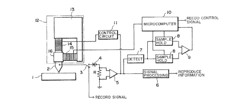
Fig. 2 is a block diagram which illustrates
the structure of the first embodiment of a memory
apparatus according to the present invention. As
shown in Fig. 2, the memory apparatus according to
this embodiment comprises: a probe electrode 2;
tracking means (not shown) for causing the probe
electrode 2 to face the surface of a recording medium
- 9 - ~s~
l having information lines, which has been sequentially
recorded as pits and projections on the surface or
changes in the electronic states, to relatively travel
along the information line; voltage applying means
(not shown) for applying voltage between a recording
medium l and the probe electrode 2 to generate a tunnel
current; a bias voltage source 4, a resistor R, an
amplifier 5 and a signal processing cirauit 6 for
converting the tunnel current signal into a voltage
signal to reproduce informations recorded on the
recording medium l; a detection circuit 7 for
detecting the change in the intensity of an envelope
signal of the tunnel current signal which has been
converted into the voltage signal output from the
amplifier 5; two sample hold circuits 8; comparator 9;
microcomputer lO; and piezoelectric ceramics 15 for
finely moving the probe electrode 2 in an intersecting
direction tperpendicular direction) in relation to
forming direction of the information lines on the
recording medium l, on the basis of the result of the
detection.
The recording medium l is illustrated by its
cross section in a direction perpendicular to the
record bit line. The recording medium l may be made
of a material having the current and voltage character-
istics which shows a memory switching phenomenon, i.e.,
a material showing a phenomenon o~ reversible
- lo - ~5~
1 transition in the electrical conductivity, the material
beincJ formed on a conductive substrate. The above-
described material is exemplified by: an amorphous
semiconductor such as oxide glass, borate glass, or
chalcogenide glass containing Se, Te or As combined
with an element of III, IV, V or VI group of the
periodic table; an organic compound having a group wlth
conjugated ~ electronic level and a group wi-th a electronic
level in the molecule thereof; a coloring matter
having a porphin skeleton such as phthalocyanine or
tetraphenylporphin; as azulene coloring matter
having a squalillyum base and a chroconic base as a
bonding chain; a coloring matter like a cyanine in
which two heterocycles including nitrogen such as
quinoline, benzothiazole and be.nzo-oxazole are
bonded to each oth~r by the a squalillyum base and a
chroconic base; a cyanine coloring matter, a conden~ed
polycyclic aromatic group such as anthracene and
pyrene, a chain compound in which an aromatic cycle
and a heterocyclic compound are polymerized with
each other, and a polymer of a diacetylene group; a
derivative of tetraquinodimethane and diacetylene,
its analogous material, its charge-transfer complex;
and a metal complex compound such as ferrocene and
trisbipyridine ruthenium complex. The above-described
material is used in the form of a monomolecular film
or a built-up film. It is preferable to employ a
1 so-called Langmuir-Blodgett's (LB) method in which
in order to form the monomolecular film or the
built-up film of -the organic compound an amphipathic
material is molecular-oriented at a high density
on the water level to form a monomolecular film, the
molecular film being then transcribed onto the
substrate.
In this embodiment, the recording medium 1 is
constituted by l~;na$ing a base layer made of Au
and a recording layer made of amorphous Si containing
hydrogen by 30 atom~ on a glass sùbstrate.
The probe electrode 2 have an end portion
sharpened as much as possible by etching or
electropolishing~ In this embodiment, the probe
electrode 2 is produced in such a manner that a rod
of tungsten having a diameter of 1 mm~ is mechanically
polished to foxm into a conical shape having an
angle of 90~, and then an electric fleld is applied
to ths same under ultra high vacuum to evaporate the
surface atoms. However, the present invention is
not limited to the above-described shape, the
producing method and the material of the probe
electrode 2~
In order to read out informations, the distance
from the recording medium 1 to the probe electrode 2
serving as a pickup must be the distance which enables
a tunnel current generated due to the tunnel effect to
- 12 - ~ ~5~
1 be detected. The distance from the probe electrode 2
to the recording medium 1 and their relatlve position
are controlled by an actuator 12. The actuator 12
comprises a fixed base 13, a movable base 16 and
piezoelectric ceramics 14 and 15 such as a PLZT or a
PZT. The movable base 16 is connected to the probe
electrode 2. When control voltage is applied to
the same to extend/contact the piezoelectric ceramics
14 and 15 the probe electrode 2 can be moved in Z
direction ~vertical direction) or XY direction
(lateral direction) with respect to the recording
medium 1.
Informations can be recorded on the recording
medium 1 by using the apparatus thus-constitu~ed in
such a manner that writing pulse voltage having the
wave height value of which is 5 V and the pulse width
of which is 1 ~sec is applied 1:o the probe electrode 2
to pass the tunnel current to the recording position
when a switch 3 is switched on as shown in Fig. 2 and
the probe electrode 2 is moved. As a result, record
bits having the diameter of each of which is about
10 nm are formed on a straight line at a pitch of 15
nrn .
Then, a tracking control to be performed
upon reproducing operation for reading out the
siynals recorded on the recording medium 1 in the
above-described manner will now be described. The
- 13 - % ~
l switch 3 is switched over to the opposite terminal
shown in Fig. 2
First, the distance from the probe electrode
2 and the recording medium l is set in order to
obtain the tunnel current in the control circuit 11.
By operating the probe electrode 2 along the infor-
mation bit line formed on the recording medium l for
the purpose of reading out informations, the tunnel
current passing through the probe electrode 2 changes
in accordance with the record bits (curve TN shown in
Fig. 3A). A curve EV shown in Fig. 3A shows the
envelope of the above-described tunnel current signal.
It can be considered that the increase/decrease of the
absolute value of the envelope substantially coincides
with incresae/decrease in the amplitude of a signal
(i~~ormation bit signal component) which corresponds
to the recording bits. The above-described signal
current i5 I V transformed through the resistor R and
then it is amplified by the amplifier 5. Then, the
output from the amplifier 5 is supplied to khe
signal processing circuit 6 so that reproduction
information of "ON" or "OFF" is obtained. The output
from the amplifier 5 is also supplied to the detection
circuit 7 in which the reproduce signal is envelope-
detected before supplied to the two sample hold
circuits 8. Each of the sample hold circuits 8
alternately updates the envelope absolute values by
%q~
- 14 -
1 using sample pulses transmitted from the microcomputer
10. Then~ the envelop absolute values are sequentially
subjected to comparisons by the comparator 9. Fig.
3B illustrates an example of each of outputs Sl and
S2 from the corresponding sample hold circuits 8.
The result of the comparison is taken in into the
microcomputer 10 to discriminate -the direction of the
voltage to be applied to the piezoelectric ceramics
15, so that proper voltage is transmitted to the
piezoelectric ceramics 15. That is the voltage
level to be applied is changed, for example, increased
to be subjected to a comparison with the next sampling
envelope~ I~ the sampling envelope absolute value
(level) of the updated circuit is higher than the
sampling envelope level of the other circuit, the
level of the applied voltage is allowed to increase
(if the same i5 lower, the voltage level is
decreased to be sub~ec~ed to a comparison with the
next sampling envelope. Then, until the update side
envelope level is decreased in comparison with that
of the opposite side sample (until the same is
increased in the contrary case) the applied voltage
is changed in the same direction, that is, the probe
electrode 2 is displaced in the same direction. As
described above, the control voltage is applied to the
piezoelectric ceramics 15 to control the lateral
directional position of the probe electrode 2 so
- 15 ~
l that the envelope level of the reproduce signal
becomes the maximum le~el, whereby the probe electrode
2 is positioned at the most suitable position in the
stable state and the tracking can be automatically
performed.
For example, the period of the sampling
pulse is set to be longer than the period o~ the
information bits, and the voltage displacement per
step to be supplied from the microcomputer lO to the
piezoelectric ceramics 15 is set to be l nm, whereby
the envelope level o~ the reproduce signal can be
brought into a stable state and the tracking can
be performed with an accuracy of + 1 nm.
Although the envelope level is used in the
above-described embodiment, another method may be
employed in which the amplitude of the information
bit s.ignal component is directly detected and the
probe position is controlled in the direction in
which the amplitude thus-detected is enlarged~
Furthermore, tracking may be performed by driving the
portion including the recording medium l.
According to this embodiment tracking infor-
mation can be generated from the reproduce signal
without wobbling. Therefore, an advantage can be
obtained in that information can be read out with
excellent reproducibility.
Then, a second embodiment of the present
- 16 - ~ ~5
1 invention will now be described.
Fig. 4 is structural view which illustrates a
memory apparatus according to this embodiment. A
recording medium 23 on to which a base electrode 22
is fixed, is placed on an XY major moving mechanism
21 mainly composed o~ parallel springs made of
elastic hinges and capable of coarsely moving on the
XY plane. A probe electrode 25 fixed to a th.ree-
dimensional fine moving mech~nt~.~ 24 made of a
piezoelectric element is disposed above the recording
medium 23. A voltage application circuit 26 and a
current detection circuit 27 are conn~cted to the
recording medium 23 and the probe electrode 250 r~he
voltage application circuit 26 and the current
detection circuit 27 are connected to a microcomputer
28~ The output from the current detection circuit 27
is transmitted to integrators 2ga and 29b. The
outputs from the integratoxs 29a and 29b are trans-
mitted to a differential circuit 31 through hold
circuits 30a and 30b, respectively. The output from
the differential circuit 31 is ~ransmit~ed to a
drive circuit 32 which is connected to *he XY major
moving mechanism 21, the 3-D fine moving mechanism
24 and the microcomputer 28.
The probe electrode 25 may be used in which
the edge portion o~ pin o~ tungsten, Pt-Ir, Pt, or
the like is mechanically polished and then is
- 17
1 electrolytic polished. The recording medium 23 is
produced in such a manner that a material similar to
those in the first embodiment having a memory effect
in relation to switching characteristics of the
voltage current is used in, for example, the
Langmuir's-Blodgetts (LB) method so that four layers
of squalillyum-bisr6-octyl azulene are formed on a
graphite substrate.
At the time of the recordiny operation and the
reproducing operation~ the XY major moving mechanism 21
and the 3-D fine moving mechanism 24 are driven ~y
the microcomputer 28 and the drive circuit 32, so
that the positional relationship between the recording
medium 23 and the probe electrode 25 is coarsely set.
At the time of the recording operation, the
XY major moving mechanism 21 and the 3 D fine moving
mechanism 24 are driven by the drive circuit 32,
so that the probe electrode 25 is relatively scanned
above the surface of the recording medium 23. Then,
the pulse voltage is applied between the probe
electrode 25 and the recording medium 23 by the
voltage application circuit 26. As a result, portions
having different electric resistance levels are
locally created on the surface of the recording medium
23 to perform recording.
At the time of the reproducing operation, the
tracking control is performed in a method to be
- 18 -
1 described later while a constant voltage is applied to
such a degree that the tunnel current flows between
the probe electrode 25 and the recording medium 23l
so that the data lines formed on the recording medium
23 are scanned by the probe electrode 25. The tunnel
current obtained at the above-described scanning
operation is detec-ted by the current detection circuit
27. Then, the 3-D fine moving mechanism 24 is driven
by the drive circuit 37 so that the average value of
the tunn01 current becomes a substantially constant
value~ whereby the probe electrode 25 is vertically
moved. Since the distance of the vertical movement
at this time corresponds to recorded informations,
reproducing data is generated in accordance with the
distance of the vertical movement.
Then, the tracking control method will now be
described. The signal line is preliminarily scanned
two times for tracking the signal line. The de~ection
signal obtained by the preliminary scanning is used to
perform third recording/reproducing tracking. Fig. 5
illustrates signal line L, first and second preliminary
scanning loci Ml and M2. The two times of prel;~;n~ry
scanning operations are performed in parallel at an
interval smaller than the diameter of recoxding bit
B of the signal line L so that the two prel' inAry
scanning loci Ml and M2 pass on the signal line L.
The tunnel currents detected by the current detection
- 19 - ~5~
1 circuit 27 at the time of the first and second
preliminary scanning operations are integrated by
lntegrators 29a and 29b, respecti~el~. The
integration results Ia and Ib are held by hold
circuits 30a and 30b. When the second preliminary
scanning operation has been completed, the differ-
ential output denoting the difference tIa ~ Ib)
between the integration results obtained by the
differential circuit 31 is transmitted to the
drive circuit 32.
Fig. 6 illustrates an example of each of the
two preliminary scanning loci Ml and M2. Fig. 7
illustrates the rela~ionship b~tween the displacement
of the prel ;r;n~ry scanning loci M1 and M2 in relation
to the record bit B and the di~ferential output from
the differential circuit 11. In a case wher2 the
distance from center O of the record bit B to the
preliminary sc~nn; ng locus Ml is equal to that to the
prel;~inary scanning locus M2, the integration results
Ia and I~ become equal. Therefore, the differential
output becomes 0. If the intermediate position
between the two prel irin~ry scanning loci Ml and M2
is displaced to the right with respect to the record
bit B, the integration result Ia increases and the
integration result Ib decreases. As a result, the
differential output increases. If the intermediate
position is displaced to the left, the integration Ia
- 20 - ~ ~5
1 decreases and Ib increases.
Since the interval between the two preliminary
scanniny loci Ml and M2 iS a known value, the
displacement between the intermediate position
betw~en the two preliminary scanning loci Ml, M2 and
the center 0 of the actual record bit B can be
detected from the differential output. sy performing
the third tracking scan in accordance with the
displacement thus-detected, the probe electrode 25
can be controlled so as to pass near the central
position of the signal line L. The hold circuits 30a
and 30b are reset before the next pre-scanning
operation is performed, so that the influence of the
previous scanning operation can be el ;m; n~ted~
The number of times of the preliminary
sC~nn;ng operations to be performed is not limited to
the two times. The pre-scanning operations may be
performed plural times, for example, three or more
times. Also the present invention can be adapted to
an apparatus capable of performing only the recording
operation or that capable of performing only the
reproducing operation.
As described a~ove, the tracking method
according to this embodiment is arranged in such a
manner that one signal line is subjected to, for
example, two times of preliminary scanning operations
at the time of the reproducing operation. l'he
- 21 - ~ ~5~ 3~
1 physical quantity of the recording medium de-tected
by the probe is used to detect the displacement
between the central position of the signal line and
the preliminary scanning position. Since the
recordinglreproducing scanning operation is performed
in accordance with the displacement thus-detected,
the tracking accuracy can be improved and the S/N
ratio at the time of the reproducing operation can
be improved~ Furthermore, the reliability of the
reproduce signal can be improved.
Although the invention has been described in
its preferred form with a certain degree of
particularly, it is understood that the present
disclosurP of the preferred form has been changed in
lS the details of construction and the combination and
arrangement of parts may be re~orted to without
departing from the spirit and the scope of the
invention as hereinafter claimed~