Note: Descriptions are shown in the official language in which they were submitted.
PAT ~ ~ ~ 3
INSULATING PLUG FOR USE IN ELECTRIC CONNECTORS
1 FIELD OF THE INVENTION:
This invention deals with a plug of electrically
insulating material, of the type adapted to be inserted in
a connector box for accommodating electric contacts. The
invention is particularly concerned with a connector
including such a plug for insertion into a box accommodating
electric contacts intended for connection to a printed
circuit board.
BACKGROUND OF THE INVENTION:
Plugs of electrically insulating material are
already known in the prior art. For example, patents
already disclose electric connectors having particular
shapes of position coding means to allow a selective
positioning relative to a reception device. In a similar
way, the prior art discloses the use of multiple coding ~eys
which may be assembled and placed in various positions in
order to realize several combinations of unique codes
between the recesses of the connectors and the connecting
elements. However, the above-mentioned documents mostly
disclose coding keys designed to be typically used outside
the openings of the box housing the connectors, which is
provided for supporting electric contacts.
In particular, the DE-A-2,455,409 and US-A-
4,478,469 appear to show the use of locking or coding
elements conceived to be disposed in the same slots or
openings of the connector box, which are used for receiving
the electric contacts. However, neither of these two
documents, nor any of the above-mentioned prior art,
discloses the use of an insulating plug which, not only is
insertable inside the same openings or recesses as those
intended to receive the connecting electrical contacts, but
also has two resilient areas, i.e., one having a connecting
function in one opening of the connector box and the other
: to be inserted in an opening of the printed circuit board.
~ -2- 2~13Q~
1 SUMMARY OF THE INVENTION:
An object of the present invention is to provide
a plug of electrically insulating material, of the above-
mentioned type, the plug having at least two resilient areas
which constitute at least a first element connectable in a
bore of the connecting box for receiving the contacts and a
second element intended to be inserted in a corresponding
recess or opening of a printed circuit board which is to be
connected with the box in order to achieve electrical
connection between the electric contacts supported in the
connector box and the printed circuit board.
According to a first advantageous feature of the
invention, the first and second above-mentioned elements of
the plug constitute part of the plug.
lS According to a preferred embodiment of the
invention, the first element constitutes the essential part
or elongate body of the plug and has a substantially
rectangular transverse section, in the shape of a hook or a
U which determines or defines an axial bore of the plug.
The second element constitutes an extension of said body as
a prolonged extremity thereof. At the free extremity of the
body of the plug opposed to the second element, an axial
bore opens at its outside or, according to an alternative
modification, the axial bore is closed and is extended by a
pin or nip having the shape adapted to close a corresponding
bore of the connector box.
According to another embodiment of the invention,
the plug is a double plug which includes two first elements
connected with single second element, the two first elements
being intended to be inserted in a connector box adapted to
receive two rows of contacts. The two connecting elements
extend substantially in parallel with the U-sections
disposed in opposite directions.
According to still another aspect of the
3s invention, the second element has the shape of a horseshoe
defining an axial bore which:
_3_ 2~
1 - in the case of a plug with a single first
element, extends in alignment with the axial bore of the
single first element;
- in case of a double plug with two first
elements, extends between the axial bores of the two first
elements in the extension thereof, two arms of the second
element, in the shape of a horseshoe defining two rest
surfaces for two first elements, the axial bores of which
end, partially, in opposite directions on each side of the
rest surfaces.
According yet to still another aspect of the
invention, a first element has, on one of its external
surfaces, a loc~ing member adapted to be connected in a
corresponding transverse bore of the connector box.
The plug of the invention is thus intended to
provide three functions, i.e. a centering function for the
electric connector in its housing or recess in the box, a
mechanical link between the box and the printed circuit
board, and a coding function in order to provide a desired
positioning of each contact to thereby preveDt the mis-
introduction of a particular electric contact in a
particular recess of the box.
BRIEF DESCRIPTION OF T~E DRAWINGS:
Other features and advantages of the invention
will appear further from the description which will follow:
In the appended drawings, given as non-limiting
examples:
Figures lA and lB show, in perspective, two
embodiments of an insulating plug according to the invention
with a single first element.
Figures 2A and 2B show, in perspective, two
embodiments of an insulating plug according to the invention
having two first elements; and
Figure 3 represents two insulating plugs with a
single first element located in a connector box with one row
of connectors.
-4- ~ 3~6
1 DETAILED DESCRIPTION OF T~E PREFERRED EMBODIMENT:
Figures lA, lB, 2A and 2B show four embodiments of
a plug of electrically insulating material, according to the
- present invention, of the type intended to be inserted in a
box for the location of plural electric contacts, in a
manner which will be described hereafter.
Figures lA and lB respectively represent
insulating plugs 1 and 2 intended to be inserted in a
housing box 10 (see Figure 3) including a single row of
connectors, whereas Figures 2A and 2B respectively represent
insulating plugs 3 and 4 intended to be inserted in a box
(not shown) with two contact rows.
As shown in Figures lA, lB, 2A and 2B, an
insulating plug 1, 2, 3, 4 according to the invention
includes at least a first element 5 constituting the
essential part or the body of the plug and which is
insertable in a bore 11 of box 10 for location of the
contacts (Figure 3) and a second element 6 defined to be
inserted in a corresponding opening of a printed circuit
board (not shown) to which the box 10 is connected in order
to achieve electrical connection between the electric
contaets supported in the box 10 and the printed cireuits on
the board.
Elements 5 and 6 of the plug are formed of an
electrically insulating material, as a convenient plastic
material, and, according to an advantageous feature of the
invention, constitute a single part.
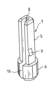
First element 5 has the general shape of an
elongate bar having a transverse section which is
substantially rectangular, in the shape of a hook or U which
defines an axial bore 8 (in Figures lA and 2A) and 14 (in
Figures lB and 2B).
In the case of Figures lA and 2A, which more
particularly represent insulating plugs 1 and 3
respectively, designed for the positioning of an electric
contact inside a corresponding bore as 11 (Figure 3) of box
_5_ 2~ 3~
1 10, axial bore 8 is opened on the opposite side of second
element 6, externally to plugs 1, 3.
In case of the plug represented in Figures lB and
2B, which is particularly intended to be used as locking
element, i.e., for preventing the introduction of a
particular contact in a determined recess 11 of box 10 (see
more particularly Figure 3), at the extremity of the
insulating plug 2, 4, opposed to second element 6, the axial
bore 14 is closed and extended by a mem~er having the shape
of a lug or stud 7, shaped for closing the corresponding
bore 11 of the connector box 10 (see Figure 3), so that the
introduction of an electric contact of a connector in the
bore 11 is not permitted. In this case, the insulating plug
2 or 4 according to the invention provides a particular
function of locking or coding.
Figures 2A and 2B illustrate an embodiment of the
invention wherein the insulating plug 3 or 4 has two first
elements 5 connected with a second single element 6, these
two elements 5 being intended to be inserted in a box 10
(not shown) designed to receive two rows of electric
contacts which are disposed in parallel one with each other.
As shown in the drawings, the second element 6,
which has for an object to provide a mechanical link between
the connector box 10, and a printed circuit board, has the
shape of a horseshoe, the thickness of which, in the shown
examples, is much smaller than the length of the elements 5,
this horseshoe defining an axial bore 13 which:
- in case of Figures lA and lB, which show
insulating plugs 1 and 2 intended for a connector box 10
with one row of electric contacts, extends in alignment with
the axial bore 8 or 14 of the first element 5;
- in case of Figures 2A and 2B, which represent
more particularly insulating plugs 3 and 4 intended for a
connector box 10 with two parallel rows of electric
contacts, has the shape of a horseshoe delimiting, on the
side opposed to a printed circuit board, two rest surfaces
6a and 6b of the two first elements 5, the axial bores 8 and
-6- 2~3~
1 14 respectively of which open partially on each side of the
rest surfaces 6a, 6b and partially in correspondence with
the rest surfaces 6a, 6b.
When the insulating plugs 1 and 3, according to
the invention, are more particularly used for providing
centering and/or positioning member for electrical contacts
in a connector box 10, the above-described design of the
insulating plug, i,e., more particularly the presence of
bore 8 in the first element 5 and bore 13 in the second
element 6 allows a mechanical link between the contacts of
box 10 and the corresponding traces on the printed circuit
board, in a very advantageous manner, by means of element 6
of the plug.
In Figure 3 there is shown a connector box 10. In
a bore 11 illustrated on the left portion of the connector
~ox the insulating plug 2 shown on Figure lB is in locking
position. More particularly, due to lug 7, plug 2 in box 10
prevents the introduction of an electric contact in its
corresponding bore. It is also depicted in Figure 3, that
the first element 5 has, on one of its external surfaces, a
locking member 9 (which can also be seen on Figures 1
through 4) having the shape of a protuberance adapted to
connect, when inserting the plug, in a corresponding
transverse bore 12 of box 10. In case of a plug having two
elements 5, each element 5 may include a locking member, as
member 9, or a single element 5 includes the locking member
9.
The invention provides therefore, in a particular
and simple design, an insulating element capable of
providing three essential functions, when a connector box
with plural electrical contacts has to be electrically
connected to a printed circuit board, i.e. a coding
function, a positioning function of the electric contacts in
their respective recesses of the box, as well as a
mechanical link function between the connector box and the
printed circuit board.
-
2 1~ Q 6
1 The invention is not limited to the pre~erred
embodiments described and shown in the drawings, but is more
particularly defined by the following claims, wherein the
reference numerals have a clarification purpose and are not
intended to limit the scope of the invention.