Language selection

Search

Patent 2051318 Summary

Third-party information liability

Some of the information on this Web page has been provided by external sources. The Government of Canada is not responsible for the accuracy, reliability or currency of the information supplied by external sources. Users wishing to rely upon this information should consult directly with the source of the information. Content provided by external sources is not subject to official languages, privacy and accessibility requirements.

Claims and Abstract availability

Any discrepancies in the text and image of the Claims and Abstract are due to differing posting times. Text of the Claims and Abstract are posted:

  • At the time the application is open to public inspection;
  • At the time of issue of the patent (grant).
(12) Patent: (11) CA 2051318
(54) English Title: VEHICLE REFLECTOR UNIT
(54) French Title: ENSEMBLE REFLECTEUR POUR VEHICULE
Status: Deemed expired
Bibliographic Data
(51) International Patent Classification (IPC):
  • B60Q 1/26 (2006.01)
  • B60Q 1/32 (2006.01)
(72) Inventors :
  • COLIGIONIS, GEORGE (South Africa)
(73) Owners :
  • COWLING, PETER JOHN (South Africa)
(71) Applicants :
(74) Agent: GOWLING WLG (CANADA) LLP
(74) Associate agent:
(45) Issued: 1996-03-12
(22) Filed Date: 1991-09-16
(41) Open to Public Inspection: 1992-03-15
Examination requested: 1993-02-10
Availability of licence: N/A
(25) Language of filing: English

Patent Cooperation Treaty (PCT): No

(30) Application Priority Data:
Application No. Country/Territory Date
90/7341 South Africa 1990-09-14

Abstracts

English Abstract


This invention relates to a reflector unit for
attachment to the sides of abnormally long vehicles
and trailers. The reflector units have reflecting
surfaces which reflect incident light towards the
rear, sides and front of the vehicle thereby
providing an indication, particularly at night, of
the overall length of the vehicle. It is envisaged
that this will reduce the hazards of overtaking
abnormally long vehicles at night.


Claims

Note: Claims are shown in the official language in which they were submitted.


- 10 -
The embodiment of the invention in which an exclusive property or privilege is
claimed are defined as follows:


1. A method of enhancing the visibility of a vehicle, and for providing an
indication of the relative length of said vehicle, comprising the steps of:
attaching at least three reflector units, each having at least one reflective
surface operative to reflect and send light towards each of the rear, side and front of the
vehicle, along at least one side of the vehicle;
spacing said reflector units along said at least one side at a predetermined
constant distance from one another, thereby providing a series of equally-spaced
reflectors along said side of the vehicle and thus providing said indication of the length
of said vehicle; and
orienting said reflector units in use, so as to reflect incident light towards
the rear, side and front of the vehicle.
2. The method of claim 1, wherein said reflectors are attached to said vehicle
by means of screw threaded fasteners and nuts.
3. The method of claim 1, wherein said reflectors are attached to said vehicle by
means of an adhesive.
4. A method of enhancing the visibility of a vehicle, and for providing an
indication of the relative length of said vehicle, comprising the steps of:
attaching at least three reflector units, each having at least one reflective
surface operative to reflect and send light towards each of the rear, side and front of the
vehicle, along the underside of the vehicle adjacent at least one side thereof;
spacing said reflector units adjacent said at least one side at a
predetermined constant distance from one another, thereby providing a series of equally-


- 11 -

spaced reflectors adjacent said side of the vehicle and thus providing the indication of the
length of said vehicle; and
orienting said reflector units in use, so as to reflect incident light towards
the rear, side and front of the vehicle.
5. The method of claim 4, wherein said reflectors are attached to said vehicle
by means of screw threaded fasteners and nuts.
6. The method of claim 4, wherein said reflectors are attached to said vehicle
by means of an adhesive.


Description

Note: Descriptions are shown in the official language in which they were submitted.


20~1318


VEHICLE REFLECTOR UNIT

INTRODUCTION

This invention relates to a reflector unit for
mounting on the sides of vehicles.

BACRGROUND TO THE INVENTION

In many countries it is compulsory for vehicles
which are used on public roads and thoroughfares to
have light reflectors mounted on the rear of the
vehicles. In addition to the standard reflectors,


2051318
most heavy vehicles and trailers have light
reflecting chevrons mounted at the rear of the
vehicle to warn other vehicles approaching from the
rear that an abnormally long vehicle is ahead.


One problem encountered by road users is that when
travelling at night, while the rear reflectors and
chevrons warn one that a heavy or abnormally long
vehicle is ahead, they give no indication of the
overall length of the vehicle. Attempts have been
made to partly alleviate this problem by printing,
in numerals or letters, the length of the vehicle
at the rear of the vehicle but, in the absence of
visible reference points, it remains difficult to
judge the distance, particularly at night, and,
consequently, hazardous to execute an overtaking
manoeuvre.


The same difficulty can apply to the assessment of
the length of a truck from the front and side.


OBJECT OF THE lNv~ lON


It is an object of this invention to provide a


205131~

reflector unit which at least partly alleviates the
above difficulties.


Y OF TU~ TNV~NTION


In accordance with this invention there is provided
a reflector unit securable to the side of a vehicle
and having reflective surfaces capable of
reflecting incident light towards the rear, side
and front of the vehicle.


There may be a single arcuate face arranged in use
to reflect incident light towards the rear, side
and front of the vehicle, or separate reflective
surfaces.


There is further provided for the reflector unit to
be securable to the side of the vehicle by means
of an adhesive strip, alternatively there is
provided for the reflector unit to be so securable
by at least one bolt and nut, the bolt extending
approximately normally from the base of the
reflector unit and which, in use, is locatable


2051318
through an aperture in the side of the vehicle
whereupon it is secured by the nut.


Further features of the invention provide for the
reflector unit to be of a plastics material and for
the reflective surfaces to be formed by light
reflective tape, alternatively for the reflective
surfaces to be formed by reflective plastics
material or glass lenses.


The invention extends to a method of enhancing the
visibility of a vehicle comprising attaching a
number of the above reflector units in a spaced
apart configuration to at least one side of the
vehicle, the reflector units being orientated to
reflect incident light towards the rear, side and
front of the vehicle and for thé spacing between
the reflector units to be approximately equal to
the spacing between reflector units used to
demarcate roadways.


The invention extends to a vehicle having a number
of the above reflector units attached to at least
one of its sides.


2051318
BRIEF DESCRIPTION OF THE DRAWINGS
The above and additional features of the invention will be described below by way of
example only and with reference to the accompanying drawings in which:
Figure 1 is an isometric view of one embodiment of a reflector unit
according to the invention;
Figure 2 is an isometric view of a second embodiment of a reflector unit
according to the invention; and
Figure 3 is an underplan view of a third embodiment of a reflector unit
according to the invention.


DETAILED DESCRIPTION OF THE DRAWINGS
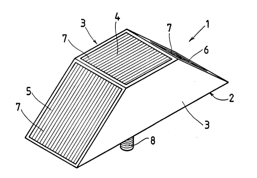
Referring to Figure 1, a reflector unit (1) is fabricated from a plastics material and has
a substantially planar rectangular base (2) with a pair of trapezoidal substantially
vertical sides (3) extending from the long sides of the base. The trapezoidal sides (3)
15 are arranged so that they form an approximately planar square face (4) parallel to the
base (2) and a pair of inclined faces one (5) orientated operatively rearwards and the
other (6) orientated operatively frontwards.

X


2051318


Incident light reflectors (7) of a reflective plastics material are located within suitably
shaped recesses in each of the faces (4), (5) and (6). The depth of the recesses is such
that the reflectors (7) are flush with the surfaces of the faces. The reflector unit has
5 a bolt (8) extending approximately normally to the base (2).
In use, the bolt (8) is located through an aperture in the side body panel or chassis of
an abnormally long vehicle or trailer, the reflector unit orientated such that the faces
(4), (5) and (6) will reflect incident light towards the side, rear and front respectively
of the vehicle or trailer. Once orientated, the reflector unit is firmly affixed to the side
10 of the vehicle or trailer by a nut located on the opposite side of the body panel to the
reflector unit. Ideally a number of reflector units are affixed to both sides of the
vehicle or trailer, the units being spaced apart by a constant distance of one metre.
Referring to Figure 2, a reflector unit (10) has a substantially planar rectangular base
(1 1 ) and a pair of part circular substantially vertical sides (12) extending from the long
15 sides of the base (11). The arcuate surface (13) formed by the sides (12) has a strip
of light reflective tape (14) attached thereto which extends from one of the short sides
of the base (11) to the opposite short


2051 3I 8
- 8 -


side. The base (11) has a strip of double-sided adhesive tape (15) attached thereto for
mounting the reflector unit (10) to the sides of a vehicle or trailer.
In use, the backing paper of the adhesive tape (15) is removed, the reflector unit (10)
5 orientated such that incident light will be reflected towards the rear side and front of
a vehicle, and the reflector unit is firmly pressed against the side of the vehicle or
trailer. Ideally, where a number of reflector units are used, the spacing between the
units should be one metre.
Referring to Figure 3, a reflector unit (20) has a substantially planar rectangular base
10 (21) and a top face (not shown) spaced apart from the base by four sides (22), (23),
(24) & (25). The top face is larger than the base and side (22) is approximately
normal to the top face and base (21). Consequently the sides (23), (24) & (25) are
angled. Incident light reflectors (26) are affixed to each of the angled sides (23), (24)
& (25).
15 In use, a number of these reflector units are affixed to the undersides of a vehicle
adjacent its sides so that incident light is reflected towards the rear, side and front of
the vehicle. The


2~51~18

g


reflector units can be so affixed by means of a bolt and nut as described for the first
embodiment, or by means or double-sided adhesive tape as described for the second
embodiment. When affixed to the vehicle, each unit should be spaced apart by a
5 constant distance of one metre.
It will be appreciated that variations can be made to the above described reflector unit,
in particular, the reflecting surfaces can be multi-faceted and the reflectors can be
arranged to reflect incident light towards the operatively upper and lower aspects of
the unit, and the means for attaching the reflector unit to the sides of a vehicle can be
10 altered as can the spacing between units, without departing from the scope of the
invention.


Representative Drawing
A single figure which represents the drawing illustrating the invention.
Administrative Status

For a clearer understanding of the status of the application/patent presented on this page, the site Disclaimer , as well as the definitions for Patent , Administrative Status , Maintenance Fee  and Payment History  should be consulted.

Administrative Status

Title Date
Forecasted Issue Date 1996-03-12
(22) Filed 1991-09-16
(41) Open to Public Inspection 1992-03-15
Examination Requested 1993-02-10
(45) Issued 1996-03-12
Deemed Expired 2011-09-16
Correction of Expired 2012-12-02

Abandonment History

There is no abandonment history.

Payment History

Fee Type Anniversary Year Due Date Amount Paid Paid Date
Application Fee $0.00 1991-09-16
Registration of a document - section 124 $0.00 1992-04-03
Maintenance Fee - Application - New Act 2 1993-09-16 $100.00 1993-09-15
Maintenance Fee - Application - New Act 3 1994-09-16 $100.00 1994-09-06
Reinstatement: Failure to Pay Application Maintenance Fees $200.00 1995-10-26
Maintenance Fee - Application - New Act 4 1995-09-18 $100.00 1995-10-26
Maintenance Fee - Patent - New Act 5 1996-09-16 $150.00 1996-08-09
Maintenance Fee - Patent - New Act 6 1997-09-16 $150.00 1997-08-19
Maintenance Fee - Patent - New Act 7 1998-09-16 $150.00 1998-09-10
Maintenance Fee - Patent - New Act 8 1999-09-16 $150.00 1999-09-13
Maintenance Fee - Patent - New Act 9 2000-09-18 $150.00 2000-09-14
Maintenance Fee - Patent - New Act 10 2001-09-17 $200.00 2001-09-17
Maintenance Fee - Patent - New Act 11 2002-09-16 $200.00 2002-08-23
Maintenance Fee - Patent - New Act 12 2003-09-16 $200.00 2003-08-07
Maintenance Fee - Patent - New Act 13 2004-09-16 $250.00 2004-08-24
Maintenance Fee - Patent - New Act 14 2005-09-16 $450.00 2005-09-26
Maintenance Fee - Patent - New Act 15 2006-09-18 $450.00 2006-08-15
Maintenance Fee - Patent - New Act 16 2007-09-17 $450.00 2007-09-06
Maintenance Fee - Patent - New Act 17 2008-09-16 $450.00 2008-08-19
Maintenance Fee - Patent - New Act 18 2009-09-16 $450.00 2009-09-08
Owners on Record

Note: Records showing the ownership history in alphabetical order.

Current Owners on Record
COWLING, PETER JOHN
Past Owners on Record
COLIGIONIS, GEORGE
Past Owners that do not appear in the "Owners on Record" listing will appear in other documentation within the application.
Documents

To view selected files, please enter reCAPTCHA code :


To view images, click a link in the Document Description column. To download the documents, select one or more checkboxes in the first column and then click the "Download Selected in PDF format (Zip Archive)" or the "Download Selected as Single PDF" button.

List of published and non-published patent-specific documents on the CPD .

If you have any difficulty accessing content, you can call the Client Service Centre at 1-866-997-1936 or send them an e-mail at CIPO Client Service Centre.


Document
Description 
Date
(yyyy-mm-dd) 
Number of pages   Size of Image (KB) 
Cover Page 1996-03-12 1 16
Abstract 1996-03-12 1 14
Description 1996-03-12 8 182
Claims 1996-03-12 2 51
Drawings 1996-03-12 2 50
Cover Page 1994-03-19 1 14
Abstract 1994-03-19 1 15
Claims 1994-03-19 6 126
Drawings 1994-03-19 2 56
Description 1994-03-19 8 212
Representative Drawing 1999-07-05 1 19
Fees 2005-09-26 1 30
Prosecution Correspondence 1993-06-04 2 49
Examiner Requisition 1995-02-14 2 59
Prosecution Correspondence 1995-06-14 3 87
Prosecution Correspondence 1995-12-08 1 37
Office Letter 1993-03-24 1 42
PCT Correspondence 1993-02-10 1 34
Fees 2009-09-08 1 31
Fees 1996-08-09 1 61
Fees 1995-10-26 2 94
Correspondence 1995-12-14 1 23
Fees 1994-09-06 1 42
Fees 1995-12-21 1 30
Fees 1996-02-08 1 47
Fees 1993-09-15 1 31