Note: Descriptions are shown in the official language in which they were submitted.
2051~96
, I
MOBILE COMMUNICATION SYSTEM
BACKGROUND OF THE INVENTION
The present invention relates to a mobile communication
system using a cellular system.
In a mobile communication system, such as a mobile
telephone system, the service area is divided into a
plurality of small zones or cells, in each of which a
base radio station is arranged. This arrangement is
known as a cellular system. A cellular system effectively
utilizes frequency resources by making it possible to use
the same frequency band repeatedly between cells where no
interference occurs.
A base radio station in a mobile telephone system
primarily consists of an antenna, a duplexer, a transceiver
for conversation and control purposes and a base station
controller as described in Fig. 11.14, Fig. 11.16 and
Fig. 11.17 Mobile Telephone (in Japanese) published by
the Institute of Electronics, Information and Communication
Engineers (edited under supervision by Moriji Kuwabara).
In a cellular system, the smaller the cell size,
the more times the same frequency band can be used in
repetition. Therefore, the cell size has to be reduced
along with an increase of subscribers, and a microcellular
system of about 200 m in cell radius is predicted to become
required in the near future. In a microcellular system,
~Oal4g~
- 2 -
it would be desirable to install base radio stations on
existing street lamp poles and utility poles. However,
since each base station of any existing type involves
even a transceiver and a base station controller, it is
too large to be mounted on a street lamp or utility pole.
Moreover, since the mobile terminals move around and
perform communication in a mobile communication system,
the traffic not only is geographically uneven but also
varies from time to time. For instance, while the peak
of traffic usually occurs in a downtown center in the
daytime, it is dispersed into the suburbs at night.
Furthermore if a traffic jam arises, the traffic around
it might become significantly dense.
In order to provide adequate service quality, i.e.
to ensure a low enough call blocking probability, against
such a variable peak of traffic, the base station in each
cell should be equipped with a sufficient number of speech
transceivers to accommodate the heaviest predictable
traffic in the cell. In such an arrangement, however,
the utilization rate of each radio transceiver would
approach 100% only in the peak period, but would be
- extremely low in other periods, resulting in a poor cost
performance.
SUMMARY OF THE INVENTION
An object of the present invention, therefore is to
~ 205 1 496
66446-513
reduce the dimensions of the base radio station by utilizing the
low-noise, low-distortion and wide-band characteristics of light
beam type transmission, and using optical transmission
techniques for the concentrative handling of radio signals
transmitted from and to be received by many dispersed base
stations.
Another object of the invention is to provide an
economical mobile communication system capable of flexibly
accommodating geographically uneven traffic which also varies
from time to time.
According to the invention, there can be provided a
mobile communication system using a cellular system having at
least one cell, in which radio transceivers for performing
communication with mobile terminals are not arranged in each of
said cells but are concentrated in one or more central base
stations as a plurality or pluralities of common radio
transceivers, and said central base station or stations and said
radio transceivers are optically coupled with each other.
The invention provides a cellular mobile communication
system with M radio zones consisting of a plurality of mobile
terminals, M base radio stations one of which is provided for
each zone, a central base station connecting said base radio
stations to a mobile switching center, and the mobile switching
center connecting said central base station and a plurality of
public lines, said base radio stations being connected by
optical transmission paths to said central base station, wherein
each of said M base radio stations comprises: RF signal
,, ~ .
205 1 4 96 66446-Sl3
transceiver means for receiving RF band signals from said mobile
terminals and in turn supplying said RF band signals as first RF
signals, and for transmitting second RF signals to said mobile
terminals; first optical signal transmitting means, receiving
said first RF signals, for converting said first RF signals into
first optical signals and transmitting them to said central base
station; and first optical signal receiving means for converting
second optical signals from said central base station into said
second RF signals, and said central base station comprises: M
second optical signal receiving means, one of which is provided
for each of said M base radio stations, for receiving said
second optical signals and converting them into third RF
signals; receiving means for demodulating said third RF signals
and sending out a plurality of resultant first demodulated
signals to said mobile switching center; transmitting means for
receiving signals from said public lines via said mobile
switching center and converting the signals into fourth RF
signals; and M second optical signal transmitting means, one of
which is provided for each of said M base radio stations, for
converting said fourth RF signals into said second optical
signals, wherein each of said M base radio stations is further
provided with gain control means, to which said first RF signals
are supplied, for generating a gain control signal on the basis
of the level of a received strength of said first RF signals,
controlling the gain of said first RF signals on the basis of
this gain control signal, and supplying the gain-controlled RF
signals to said first optical signal transmitting means; and
; ~ 3a
205 1 496
66446-513
wherein each of said M base radio stations is further provided
with multiplexing means for multiplexing said gain control
signal and the gain-controlled RF signals, and supplying the
resultant multiplexed signals to said first optical signal
transmitting means, such that the received strength of said
first RF signals is determined by said central base station.
BRIEF DESCRIPTION OF THE DRAWINGS
FIG. 1 is a block diagram illustrating a first
preferred embodiment of the present invention.
FIGS. 2 and 3 are block diagrams illustrating the
configurations of base radio stations to be used in second and
third preferred embodiments, respectively, of the invention.
3b
,,
2 0 ~ 1 ~ 9 6
FIGS. 4 and 5 illustrate a fourth preferred embodiment
of the invention.
DETAILED DESCRIPTION OF THE PREFERRED EMBODIMENTS
Now will be described a first preferred embodiment
of the present invention with reference to FIG. 1, which
illustrates an arrangement of three cells belonging to a
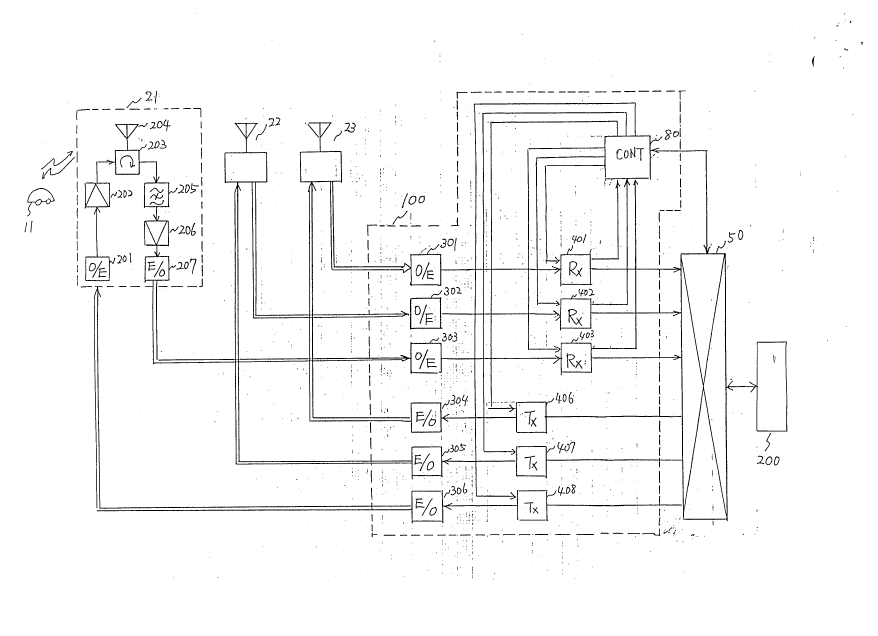
central base station. This first embodiment comprises
base radio stations 21, 22 and 23 one of which is provided
in each cell and transmits and receives signals to and
from mobile stations at a radio frequency, and a central
base station 100 connected to the base radio stations by
optical fibers.
The base radio station 21 consists of an optical-to-
electric (O/E) converter 201 for converting optical
transmit signals supplied via optical fibers from the
central base station 100 into transmit signals of the
RF band; an amplifier 202 for amplifying the O/E converter
201 to a prescribed level; a duplexer 203 for supplying
the output of the amplifier 202 to an antenna 204 and
supplying signals received by the antenna 204 to a band-
pass filter 205; the band-pass filter 205; a receive
amplifier 206; and an electric-to-optical (E/O) converter
207 for converting receive RF signals, which are the
output of the receive amplifier 206, into optical signals
and supplying the optical signals to the central base
2 0 ~ 1 ~ 9 ~
station 100 via optical fibers.
The central base station 100 involves O/E converters
301, 302 and 303 for converting optical receive signals
supplied from the base radio stations 21, 22 and 23,
respectively, into electric signals; and receivers 401,
402 and 403 for demodulating RF signals supplied from
the O/E converters 301, 302 and 303, respectively, into
baseband signals.
The central base station further involves transmitters
404, 405 and 406 for appropriately modulating transmit
baseband signals supplied from a mobile switching center
50 and converting them into signals of the RF band; and
E/O converters 304, 305 and 306 for converting transmit
RF signals from the transmitters 404, 405 and 406,
respectively, and sending each of the optical signals to
the corresponding base radio station via optical fibers.
The mobile switching center 50 sends out baseband
signals, supplied from the receivers 401, 402 and 403,
to a public telephone network 200, and also sends out
baseband transmit signals, supplied from the public
telephone network 200, to a transmitter designated by
a control circuit 80, i.e. the transmitter corresponding
to the cell in which is present the mobile terminal 11
which is the other party to communicate with.
In FIG. 1, as the mobile terminal 11 and the mobile
switching center 50 are similar to those generally used
20al496
and their configurations are extensively known to persons
skilled in the art, they are not described in detail
herein.
At the base radio station 21, RF signals received
by the antenna 204 are supplied via the duplexer 203, the
receive filter 205 and the receive amplifier 206 to the
E/O converter 207, which consists of a laser diode and
its driver circuit, and converted by the converter 207
into an optical signals, which are transmitted to the
central base station 100 via optical fibers. At the
- central base station 100, the receive RF signals are
first reproduced by the O/E converters 301 to 303, and
demodulated by the receivers 401 to 403 into inbound
speech signals, which are sent out to the mobile switching
center 50.
Incidentally, it is the same as in the prior art that
the receive frequencies of the receivers 401, 402 and 403
are set by a control signal from the control circuit 80,
and that call control information received via a base
radio station is sent out to the control circuit 80 to
have the control circuit 80 control the mobile switching
center 50. In a cellular system, the cell in which the
mobile terminal is located is detected on the basis of
the receive field ,intensity at the antenna of the base
radio station, and a handover is effected at the mobile
switching center every time the mobile terminal moves
20~1~g~
_ - 7
from one cell to next. The receive field intensity
information needed to make the control circuit 80 generate
the control signal for this purpose is also sent from the
receiver to the control circuit 80. In these respects,
too, the arrangement is the same as in the prior art.
Outbound speech signals from the mobile switching
center 50 are converted into optical signals by the E/O
converters 304 to 306 after being converted into transmit
RF signals by transmitters 406 to 408 in the central base
station 100. The optical signals sent out by the central
base station are entered into the O/E converter 201,
consisting of a photodiode and a front end circuit, in
the base radio station 21, and transmitted from the
antenna 204 via the transmit amplifier 202 and the
duplexer 203. The other base radio stations 22 and 23
have the same configuration.
According to the present invention, RF signals
received by the antenna of a base radio station are
converted into optical signals, which are then transmitted
to the mobile switching center via low-loss optical fibers.
Because of this feature, as illustrated in FIG. 1,
each base radio station, which needs only the O/E converter
201, transmit amplifier 202, duplexer 203, antenna 204,
band-pass filter 205, receive amplifier 206 and E/O
converter 207, is significantly reduced in dimensions,
and can be readily mounted on a utility pole.
20sl4se
-- 8 --
Whereas the foregoing detailed description referred
to the first preferred embodiment of the present invention,
it will not be always easy for this first embodiment to
secure the required level of the carrier-to-noise (C/N)
ratio for optical transmission if the level of RF signals
received by a base radio station is not high enough. In
view of this problem, a second preferred embodiment of the
invention secures an adequate C/N ratio by providing an
automatic gain control (AGC) circuit immediately before
the E/O converter 207 and amplifying therewith the radio
signals received by the antenna 204 to a prescribed output
level.
FIG. 2 is a block diagram illustrating the
configuration of a base radio station to be used in the
second preferred embodiment of the invention. Since the
configuration of the central base station in this second
embodiment is the same as in FIG. 1, only the base radio
station will be described below.
Suppose, for instance, that no more than five carriers
are used in each cell. When multiplexing five carriers and
modulating a semiconductor laser for optical transmission,
if the total modulation index surpasses 100%, a large
distortion due to overmodulation will occur to make it
impossible to achieve adequate transmission quality.
Therefore the modulation index per channel is usually
kept not to exceed 20%. Meanwhile the C/N ratio realized
20al~9~
g
in optical transmission is about 80 dB at the maximum
when the modulation index is 20%. If the modulation
index drops here, the C/N ratio that is achieved will
drop correspondingly. In a mobile communication system,
there is a difference of 60 dB or more in the level of
signals received by the antenna of a base radio station.
Therefore, a carrier of the lowest signal level may fail
to satisfy the C/N ratio requirement of 15 dB.
In the usual state in which a mobile communication
system is used, a traffic peak does not occur so frequently,
and it is rare for every carrier to have a high reception
level at the same time. Therefore, where the reception
level of a part of carriers is low, the total modulation
index of the semiconductor laser often is far lower than
100%. Therefore, if the amplitude of the high frequency
signal component with which the semiconductor laser is
modulated is detected and that amplitude is so controlled
as to cause the semiconductor laser to be always modulated
at a modulation index of approximately 100%, even a carrier
component of a low reception level will be modulated at
a substantially high modulation index, making it possible
to achieve a high enough C/N ratio.
In the base radio station of the second preferred
embodiment of the invention illustrated in FIG. 2, the
receiver amplifier 206 consists of a variable-gain
amplifier, and its output level is detected by an AGC
20al496
-- 10 --
circuit 208, with whose output signal the gain of the
receiver amplifier 206 is controlled to keep constant the
level of high frequency signals entered into the laser
diode of the E/O converter 207, its modulation index found
to be always 95%. When this mobile communication system
was actually operated, while the lowest C/N ratio of
receive signals at the central base station 100 was 15 dB
without controlling the gain of the receive amplifier 206,
the average modulation index for each carrier was increased
by the AGC circuit 208, the lowest C/N ratio being improved
to 25 dB.
The second preferred embodiment of the present
invention thus has the advantage of making it possible
to prevent the C/N ratio from being adversely affected
by a drop in receive field intensity at the base radio
station.
This second embodiment, however, involves a new
problem, which is described below. Generally in a
cellular mobile communication system, the level of receive
signals indicating the receive field intensity at the
antenna is detected at a base station to locate the
cell in which is present the mobile terminal with which
communication is desired, and control is so effected as
to send out speech signals from a public line to the base
radio station in the cell where the mobile terminal is
present. However, if an AGC circuit is used to achieve
2 0 ~ 1 4 9 ~
-- 11 --
control in such a manner that the degree of modulation
at the E/O converter remain constant irrespective of the
condition of reception as in the second embodiment here,
the receive field intensity for each channel detected at
the central base station cannot accurately reflect the
condition of reception at the antenna. A third preferred
embodiment of the invention is intended to solve this
problem newly occurring with the second embodiment.
FIG. 3 is a block diagram illustrating the
configuration of a base radio station to be used in a
second embodiment of the invention. This embodiment
differs from what is shown in FIG. 2 in that it has a
multiplexer 209 for multiplexing the output signals of
the AGC circuit 208 with receive RF signals. This
multiplexing of receive RF signals with the output
signals of the AGC circuit 208 may use either time
division or frequency division. Detailed description
of the configuration and operation of the time division
multiplexer or the frequency division multiplexer to be
used, which are well known to persons skilled in the art,
are dispensed with herein. This embodiment newly requires
a circuit for separating the receive RF signals and the
output signals of the AGC circuit 208 from the multiplexed
signals. It is evident that such a circuit can be provided
between the O/E converts 301, 302 and 303 and the receivers
401, 402 and 403 in FIG. 1 and signals representing the
20al49~
-
- 12 -
separated AGC circuit output be supplied to the control
circuit 80.
What is important here is that, in this third
preferred embodiment, the receive field intensity at
the antenna can be accurately estimated by compensating
the level of receive RF signals supplied to the central
base station 100 with the output signals of the AGC
circuit 208. Thus in this third embodiment, as in the
prior art, the central base station can accurately locate
the cell in which is present the mobile station with which
communication is desired.
FIGS. 4 and 5 illustrate a fourth preferred embodiment
of the present invention.
A first difference of this fourth embodiment from the
first is the presence of a matrix switch 60 between five
transmitters 406 to 410 and the three E/O converters 304
to 306. A second difference is that of another matrix
switch 70 between the three O/E converters 301 to 303
and five receivers 401 to 405. It also differs from the
first embodiment in that the control circuit 80 has the
additional function of generating control signals for
controlling the connections of the matrix switches 70
and 60.
The configuration and operation of the base radio
stations 21 to 23 in this embodiment are the same as those
in the first embodiment, and accordingly their description
2 ~ 9 ~
- 13 -
is dispensed with. Optical signals supplied from the base
radio station 21 are reconverted into RF signals by the
O/E converter 301. Optical signals entered from the base
radio stations 22 and 23 are also entered into the input
ports of the matrix switch 70 via the O/E converters 302
and 303, respectively. The output ports of the matrix
switch 70 are connected to the receivers 401 to 405. The
connecting state of the matrix switch 70 is controlled by
the control circuit 80 with a control signal (CONl), and
RF signals received any base radio station are distributed
to any one or more receiver or receivers. The receivers
401 to 405 can be tuned to any frequency under control by
the control circuit 80, and control signals demodulated
by the receivers 401 to 405 are sent out to the control
circuit 80, while demodulated inbound speech signals are
sent out to the mobile switching center 50.
Meanwhile, the transmitters 406 to 410 can be tuned
to any frequency under control by the control circuit 80,
and convert outbound speech signals sent out from the
mobile switching center 50 and control signals sent out
from the control circuit 80 into RF signals. The outputs
of the transmitters 406 to 410 are supplied to the input
ports of the matrix switch 60. The output ports of the
matrix switch 60 are connected to the base radio stations
21 to 23 via the E/O converters 304 to 306, respectively.
The matrix switch 60, whose connecting state is controlled
2 031 4 ~ 6
- 14 -
by the control circuit 80 with a control signal (~ON2),
can synthesize high frequency signals modulated by any
one or more transmitter or transmitters and send out the
synthesized signals to any base radio station.
The connecting states of the matrix switches 60 and
70 shown in FIG. 4 indicate that the receiver 401 and the
transmitter 406 are used for the transmission of control
signals to and from the base radio station 21. Similarly
the connecting states of the matrix switches 60 and 70
shown in this diagram indicate that the receiver 402 and
the transmitter 407 are used for the transmission of
control signals to and from the base radio station 22.
The connecting states of the matrix switches 60 and 70
shown in FIG. 4 also indicate that the receiver 403 and
the transmitter 408 are used for the transmission of
control signals to and from the base radio station 23.
For the transmission and reception of speech signals
to and from the mobile terminal 11 in the cell served by
the base radio station 21 are used the receiver 404 and
the transmitter 409. In this state, neither the receiver
405 nor the transmitter 410 is used.
If, in this state, a signal indicating the occurrence
of a new call demand in the cell served by the base radio
station 21 is given from the receiver 401 to the control
circuit 80, the control~circuit 80 will change the
connecting states of the matrix switches 60 and 70 as
205149~
- 15 -
illustrated in FIG. 5, and connects the receiver 405 and
the transmitter 410 to the base radio station 21 to let
the call begin.
Whereas all the base radio stations, receivers and
transmitters in the mobile communication system are
connected to a pair of matrix switches 60 and 70 in
the above described embodiment, it is also practicable
to let plural pairs of matrix switches accommodate the
base radio stations, receivers and transmitters in a
decentralized arrangement.
As hitherto described in detail, the present invention
helps to simplify the configuration of base radio stations,
and therefore makes it possible to realize compact enough
base radio stations to be mounted on utility poles or the
like.
Further according to the invention, the addition of
an AGC circuit to each base radio station makes possible
transmission over optical fibers at a sustained high C/N
ratio even where the level of receive radio signals is
low. Moreover, since this function enables the central
base station to know the reception level at each base
radio station, the central base station can control radio
lines accurately.
The invention also enables any unused radio
transceiver to be used by a base radio station with a
high traffic density, and thereby makes it possible to
2asl~s6
- 16 -
provide, without sacrificing economy, a mobile communication
system capable of flexibly accommodating traffic which
is geographically uneven and moreover varies from time
to time.