Note: Descriptions are shown in the official language in which they were submitted.
2 ~ r~
SAFETY TROCAR
Technical Field
This invention relates to a surgical trocar and more particularly to a
safety trocar in which the sharp cutting tip retracts into the cannula so as to
minimize the likelihood of inadvertent injury to viscera and other internal
tissue.
Description of the Prior Art
Trocars are sharp pointed surgical instruments used to puncture a
body cavity. Trocars are generally adapted to be used together with a
tubular trocar sleeve or cannula. Once the body cavity has been punctured
by the trocar, the sharp trocar is removed from the cannula, thereby leaving
the cannula extending into the body cavity. Endoscopic surgical procedures
are then performed through the cannula with accessory instrumentation such
as laparoscopes, dissectors, graspers, etc.
Commercially available safety trocars include a spring-loaded safety
shield which is adapted to cover the trocar tip once the body cavity has
been entered so as to provide an increased level of protection to internal
structures from puncture or laceration. For example, U.S. Patent No.
4,601,710 to Moll describes a trocar assembly which consists of two
subassemblies: a trocar subassembly which includes a sharp-tipped trocar
and a spring-loaded tubular safety shield positioned therearound, and a
cannula subassembly.
2~ 199
.,.~
When ready for use, Ihe trocar and safety shield of the trocar
subassembly are inserted through the cannula. The safety shield is
initially in its distal-most position covering the trocar tip. Exertion of
pressure against the skin with the trocar causes the shield to be pushed
rearwardly against the spring to expose the piercing tip of the trocar. The
tip penetrates the skin and underlying tissue with continued pressure. Once
the tip has penetrated through the wall and has entered the cavity, the
force against the front end of the shield ceases and the shield is
automatically moved back to its distally extended position. Viscera and
other internal tissue are thus protected from contact with the sharp piercing
tip and potential damage therefrom.
U.S. Patent No. 4,535,773 to Yoon suggests several alternative
safety trocar designs. In one embodiment (see Figs. 22-28), a spring-loaded
blunt probe is provided within the trocar shaft, as with conventional Verres
needles. The blunt probe is adapted to reciprocally slide through an
aperture in the trocar tip such that when the trocar tip enters a body cavity,
the blunt probe springs distally forward through the aperture to prevent
contact between the trocar tip and body organs. In a second embodiment
(see Figs. 33-36), pressure sensors or transducers are fitted into the trocar
blade surfaces and the distal end of the cannula. Sets of electrical leads
run through the trocar shaft and communicate with an alarm network in the
proximal portion of the device. A further modification is suggested in
which the trocar shaft is initially manually extended and maintained in its
extended position by a detent which protrudes through a hole in the
surrounding tubular structure. The hole aligns with a solenoid socket.
When the instrument is fully assembled and the trocar tip is forced through
20 5 ~ 4 9 9
a body wall, the electrical leads running through the trocar
shaft send electrical signals to the solenoid which, at the
appropriate instant, forces the detent from the hole, allowing
the trocar tip to withdraw into the cannula. Additional
mechanisms for effecting withdrawal of cutting implements are
also known. See, e.g., U.S. Patent Nos. 4,375,815 to Burns;
3,657,812 to Lee; and 3,030,959 to Grunert.
Summary of the Invention
It has now been found that an improved safety trocar may
be provided which, in one embodiment of the present invention,
includes:
(a) a cannula assembly comprising a cannula and a cannula
housing which define a passage;
(b) a trocar assembly comprising a sharp trocar tip, an
obturator shaft, and a trocar housing, said sharp trocar tip
and at least a portion of said obturator shaft being sized and
configured to enter said passage;
(c) means associated with the obturator shaft which
releasably maintains the trocar tip in an extended position;
(d) means for releasing the releasable obturator means;
and
(e) biasing means for retracting the trocar tip from the
extended position to a retracted position in response to
release of the releasable obturator means.
The safety trocar of the present invention is adapted to
be armed by the surgeon immediately prior to use. Arming may
be accomplished by advancing a finger which extends through the
trocar housing, by compressing the trocar housing toward the
cannula housing, or by like means. Once armed, the trocar tip
releasably protrudes beyond the distal end of the cannula.
As the surgeon presses the trocar, and more particularly the
trocar tip, against the body wall of a patient, the initial counterforce
exerted by the body wall against the trocar tip causes a mech~nism
associated with the obturator shaft to position the obturator shaft (together
with the cutting tip) for immediate retraction upon entering the body cavity.
Thus, removal of the counterforce from the trocar tip, e.g., upon entering
the body cavity, results in immediate and automatic withdrawal of the trocar
tip into the cannula under the force of a biasing means, e.g., a spring.
In a preferred embodiment of the trocar, the trocar tip is mounted
to an extension member which is reciprocally mounted to and biased away
from the obturator shaft. A latch is associated with the obturator shaft, the
latch being biased radially outward and being adapted to engage an internal
shelf formed in the c~nn~ or the obturator sleeve means when the trocar
is armed. A pawl is associated with the extension member which, upon
exertion of a counterforce against the trocar tip, is positioned and biased to
release the latch from engagement with the internal shelf. Upon the trocar
tip entering the body cavity, the pawl contacts and releases the latch from
engagement with the internal shelf. A spring which was loaded upon
arming the trocar is thus free to immediately retract the trocar tip into the
c~nnul~,
The trocar of the invention is also designed to permit m~nn~l
retraction or disarming of the cutting tip, if so desired. This is
accomplished by permitting the trocar housing to be m~nu~lly rotated with
respect to the c~nnul~ housing and/or the obturator sleeve means, thereby
diseng~ging the latch from the internal shel~ The trocar is also
~t5~9
..
typically provided with an indicator which signals the surgeon as to
whether the trocar is armed or disarmed.
For example, the relative position of the finger used to arm the
trocar may be calibrated or indexed to communicate the trocar tip position
or a window may be provided through which a trocar tip position indicator
is visible.
In one embodiment of the invention, the trocar housing comprises
two interconnected housing bodies. The two housing bodies are adapted to
reciprocate with respect to each other and preferably nest one within the
other. A mech~nicm is associated with the two housings which permits the
trocar tip to be armed by compressing the two housings such that they
assume a nested configuration. One or both of the trocar housings
preferably latch to the cannula housing when in this nested position. A
mech~nicm for manually releasing the trocar housings from the nested
configuration is also typically provided.
In a further embodiment of the invention, the trocar assembly is
provided with obturator sleeve means, typically a stationary tubular element
concentrically positioned around the obturator shaft and fixedly secured at
its proximal end to the trocar housing. An internal shelf is formed toward
the distal end of the tubular element for cooperation with the releasable
obturator means, e.g., a latch. The tubular element extends distally so as to
encircle the sharp trocar tip when the trocar tip is in its retracted or
unarmed position. However, the tubular element does not extend so far
distally as to protrude beyond the distal end of the cannula when the trocar
and cannula assemblies are combined. The obturator sleeve means protects
the trocar tip when the trocar assembly is removed or separated from the
2 ~ i 9 Y
cannula assembly, and facilitates introduction and removal of the
obturator shaft and trocar tip from the cannula assembly by providing a
smooth, uniform surface for passage therethrough.
The trocar of the present invention provides a safe and efficacious
means for g~ining access to body cavities to permit minim~lly-invasive
diagnostic and surgical procedures to be accomplished. The trocar is
equipped with a reliable mech~ni~m for effectuating immediate, automatic
retraction of the cutting tip into the c~nnnl~ Penetration force is kept to a
minimum through the unique internal mech~3nicm for releasably maintaining
the trocar tip in the armed position.
Brief Description of the Drawings
The present invention will become apparent from the following
detailed description taken in conjunction with the accompanying drawings in
which:
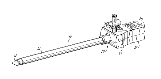
Fig. 1 is a side perspective view of a trocar of the present
invention;
Fig. 2 is an exploded view of the proximal portion of the trocar
assembly of the trocar of Fig. 1;
Fig. 3 is an exploded view of the distal portion of the trocar
assembly;
Fig. 3A is a side view of the cutting tip;
Fig. 4 is a side view, partially in cross section, of a middle portion
of the trocar assembly;
Fig. 5 is a bottom view, partially in cross section, of a middle
portion of the trocar assembly;
2 ~ 5
Fig. 6 is a front view of a middle portion of the trocar
assembly;
Fig. 7 is an exploded view of the proximal portion of the cannula
assembly;
Fig. 8 is a side perspective view of the distal portion of the cannula
assembly;
Fig. 9 is a sectional side view of the trocar with the trocar tip in its
retracted position;
Fig. 10 is a sectional side view of the trocar with the trocar tip in
its advanced position;
Fig. 11 is a sectional side ~iew of the trocar with the trocar tip
advanced, but with a counterforce (not pictured) applied thereto;
Fig. 12 is a sectional side view of an alternate embodiment of the
trocar assembly of the present invention;
Fig. 13 is a sectional top view of the alternate trocar assembly;
Fig. 14 is a sectional bottom view of the alternate trocar housing;
Fig. 15 is a sectional side view of the proximal portion of the
alternate embodiment;
Fig. 16 is a sectional side view of an alternate c~nnul~ assembly;
Fig. 17 is a sectional side view of the alternate trocar embodiment
with the trocar tip in its retracted position;
Fig. 18 is a sectional top view of a further alternate safety trocar of
the invention; and
Fig. 19 is a top view of the safety trocar of Fig. 18 with the trocar
assembly and c~nnul~ assembly separated.
2 ~ 9 ~
Detailed Description of the Invention
Referring to Fig. 1, trocar 10 is shown in its fully assembled
condition with cutting tip 12 extending from cannula 14. Trocar 10 includes
a trocar assembly 16 and a c~nn~ assembly 18. The longitudinally
extending or endoscopic portion of trocar assembly 16 which extends from
trocar housing 20 is shielded from view in Fig. 1 by cannula housing 21 and
cannula 14, except for extended cutting tip 12.
Referring now to Figs. 1 and 2, trocar assembly 16 includes trocar
housing 20 which comprises upper housing 22 and lower housing 24. Upper
housing 24 includes four mounting legs 26 which are adapted to fit within
corresponding apertures 28 in lower housing 24. Upper housing 22 also
includes two longitudinally extending, parallelly spaced, semi-hemispheric
projections 30 which face upward from top face 32 of upper housing 22.
Semi-hemispheric projections 30 surround an axial slot 34 formed in top
face 32, the function of which will be described hereinbelow.
Side faces 36 and upper face 32 of upper housing 22 step down to
form a substantially rectangular distal projection 38 and substantially
U-shaped abutment face 40. Side faces 42 and bottom face 44 of lower
housing 24 also step down to form a corresponding subst~nti~lly rectangular
distal projection 46 and a substantially U-shaped abutment face 48.
Extending distally from rectangular projections 38 and 46 are semi-circular
extensions 50 and 52, respectively. Thus, when upper housing 22 and lower
housing 24 are joined to form trocar housing 20, a tubular path is formed
into trocar housing 20.
An anchor socket 54 is formed in the rear walls 56 of upper and
lower housings 22 and 24 which receives anchor pin 58. Aperture 60 in
2~5~
pin 58 receives the proximal end 62 of tension spring 64. Tension spring
64 extends through tubular passageway 66 in ring 68. Finger 70 extends
upwardly from ring 68 and is adapted to reciprocally slide within slot 34 in
upper housing 22. The length of ~lnger 70 is preferably selected such that
its upper face 72 extends to a height equal to or less than the height of the
upper faces of semi-hemispheric projections 30. Thus, when a surgeon
grasps trocar housing 20, movement of finger 70 within axial slot 34 is
unimpeded by the surgeon's hand. Semi-hemispheric projections 30 may
take many shapes and configurations, provided free movement of finger 70
within slot 34 is ensured. Ring 68 also forms a distally directed face 74
which fits around proximally extending tubular projection 75 (see Fig. 4),
and abuts and is fixedly secured, e.g., by an adhesive, to rear face 76 of
obturator shaft 78.
Referring to Figs. 3 to 6, obturator shaft 78 includes an internal
bore 80 which begins at rear face 76 and extends to a point distal of
aperture 82. Tension spring 64 extends through bore 80 and hook 84 which
is formed on the distal end of tension spring 64 is retained by pin 86 which
extends through aperture 82 in obturator shaft 78 and a matching aperture
on the opposite face of shaft 78. When mounted within bore 80, tension
spring 64 fixedly joins obturator shaft 78 to trocar housing 20, subject to the
extension and retraction of tension spring 64.
At its distal end, obturator shaft 78 forms a hemispheric distally
extending a~n 88 and a substantially semi-circular abutment face 90. A
corresponding hemispheric tubular body 92 is adapted to mount onto
hemispheric arm 88 to provide a tubular body of substantially identical
cross-section as the proximal end of obturator shaft 78. A semi-circular
~5 ~
channel 94 is formed in the top face 96 of hemispheric arm 88. Channel
94 extends to abutment face 90 at its proximal end. A corresponding
semi-circular channel is formed in the lower face 98 of hemispheric body
92. Compression spring 100 fits within the tubular bore 101 formed by
channel 94 and the corresponding channel in hemispheric body 92.
A downwardly extending shoulder 102 is formed on top face 96 of
hemispheric arm 88 and a corresponding upwardly extending shoulder 104 is
formed in lower face 98 of hemispheric body 92. Thus, when hemispheric
body 92 is mounted on hemispheric arm along upper face 96 and lower face
98, e.g., by adhesives, sonic welding or the like, a slot 103 is formed
between shoulders 102 and 104. Two staggered pins 106 extend
downwardly from shoulder 104 and two corresponding staggered apertures
108 are formed in shoulder 102. The radially outwardly positioned pin 106
passes through an aperture 112 in latch 110 before entering the radially
outward aperture 108. The other pin 106 passes directly into the
corresponding aperture 108 and serves to align hemispheric body 92 with
obturator shaft 78. As discussed in more detail below, latch spring 114 is
positioned within the slot 103 formed between shoulders 102 and 104, nests
at its proximal end into a slot 115 formed in upper face 96, and biases latch
110. ~ Cylindrical rod 116 includes two axially spaced apertures 118 and
120 and is dimensioned to ride within tubular channel. A pin 122 fits
within aperture 120 and extends radially outward into slots 124 formed in
arm 88 (see Fig. 5~ and hemispheric member 92. Proximal face 126 of rod
116 abuts the distal end of compression spring 100.
Extension tip 128 is made up of substantially hemispheric upper and
lower tip members 130 and 132, respectively. Semicircular channels
-10-
2 ~ 9 ~
134 and 136 extend into the proximal faces 138 and 140 of upper and lower
tip members 130 and 132, respectively. Upwardly extending pin 142 is
mounted in semicircular channel 136, extends upward through aperture 118
in rod 116, and passes into an aperture (not shown) in the bottom face 144
of upper tip member 130. A second upwardly extending pin 146 extends
from the upper face 148 of lower tip member 132 through an aperture 150
in pawl 152 and into an aperture (not shown) in the bottom face 144 of
upper tip member 144. A leaf spring 154 is positioned adjacent pawl 152
and biases pawl 152 in a manner discussed in more detail below. A third
upwardly extending pin 147 provides a rotational stop to pawl 152, as is
also discussed hereinbelow.
A pyramidal cutting tip 12 having three blade surfaces 158 is
rotatably mounted into upper and lower tip members 130 and 132 by way
of matching semicircular collars 160 and 162. Pin 164 passes through a
channel formed by semicircular passages 166 and 168 in upper and lower
tip members 130 and 132. As shown in Fig. 3A, a proxim~lly extending rod
170 extends from the rear face 172 of cutting tip 12 which forms a flange
174 at its proximal end. A radial channel 176 is formed between the rear
face 172 and flange 174 into which pin 164 extends. Pin 164 thus locks tip
156 into upper and lower tip members 130 and 132 while permitting
rotational movement with respect thereto.
Turning to Fig. 7, c~nn~ housing 21 comprises upper c~nnnl~,
housing body 176 and ~ower c~nm-l~ housing body 178. A tubular port 180
is formed on upper c~nn-lla body 176 which receives stopcock assembly 182.
A flapper valve support body 184 is pivotally mounted within c~nn~
housing 21 with the lower end of support leg 186 seating into lower cannula
body 178 and the upper end passing through a helically wound
2~5~4~9
torsion spring 188, an O-ring 190, an aperture 192 in upper cannula body
176, and into cooperation with an external lever 194. The transverse leg
196 of torsion spring is positioned below lip 198 which extends from the
upper portion of flapper valve support body 184. self-seating flapper valve
200 mounts onto flapper valve support body 184 through cooperation
between aperture 202 in support body 184 and distally extending mounting
rod 204 on flapper valve 200. A seal member 206 and stabilizer plate 208
are mounted into c~nnul~ housing 21, e.g., with an adhesive, in cooperation
with internal mating flanges 210 within upper and lower cannula housings
176 and 178. Seal member 206 includes a gasket 212 which forms a gas
seal with flapper valve 200 when flapper valve support body 184 is pivoted
into a substantially parallel relation with seal member 206. A second set of
internal mating flanges 214 are provided toward the distal end of upper and
lower c~nnul~ housings 176 and 178 to receive flange 216 formed at the
proximal end of carmula 14 ~see Fig. 8).
Referring to Fig. 8, c~nn~ 14 is a hollow tubular member having
a flange 216 at its proximal end and an internal shelf 218 formed toward its
distal end. Internal shelf 218 is formed by inwardly notching or l~ncing
tubular c~nmll~ 14 at the desired location. C~nnul~ 14 is preferably
fabricated from stainless steel or a radiolucent material, as for example,
fiberglass. The length of c~nnnl~ 14 is selected such that when trocar 10 is
fully assembled, as shown in Fig. 1, trocar tip 12 is shielded by c~nmll~ 14
when the tip is retracted, but trocar tip 12 is fully exposed from c~nnul~ 14
when in its advanced position. ~nmll~ 14 may be manufactured with
various internal diameters, the most common internal diameters being 5, 10
and 12 millimeters.
-12-
2 0 ~
In use, the surgeon inserts trocar tip 12 and obturator 78 of
trocar assembly 16 into cannula housing 21. Contact with trocar tip 12
pivots flapper valve support body 184 so as to provide free passage for
trocar tip 12 and obturator 78 into cannula 14. Alternatively, flapper valve
support body 184 may be manually pivoted using lever 194. As obturator
78 enters cannula housing 21, a gas seal is provided therewith by gasket
212. The surgeon continues to advance the endoscopic portion of trocar
assembly 16 into c~nnul~ housing 21 until the front face of trocar housing
20 abuts the rear face of cannula housing 21.
Referring to Fig. 9, the initial positions of the internal mech~ni~mc
of trocar 10 are shown. In this initial position, trocar tip 12 is within
cannula 14. Latch 110 is biased radially outward against the inner wall of
c~nn~ 14 by latch spring 114. In other words, latch spring 114 biases
latch 110 counterclockwise around pin 106 into engagement with the inner
wall of cannula 14. Pawl 152 is biased clockwise by leaf spring 154 around
pin 146. Stop pin 147 prevents further clockwise motion of pawl lS2
through contact with leg 153. Pin 122 is shown in its distal-most position
within slots 124. As such, compression spring 100 is unloaded.
When the surgeon is ready to use trocar 10, finger 70 is advanced
distally within axial slot 34 in trocar housing 20. Through contact between
ring 68 and obturator shaft 78, distal movement of finger 70 also advances
obturator shaft 78 and trocar tip 12 distally, thereby exposing trocar tip 12
from c~nn~ 14. Distal movement of obturator shaft 78 also places spring
64 in tension, thereby biasing obturator shaft 78 and trocar tip 12
proxim~lly, i.e., to a position in which trocar tip 12 is shielded within
cannula 14. As shown in Fig. 10, however, such proximal motion is
by contact between engagement surface 113 of latch 110 and internal shelf
218 in cannula 14. Latch spring 114 biases latch 110 into engagement
with internal shelf 218.
With the trocar tip 12 advanced (as shown in Fig. 1), the surgeon
presses trocar 10 against a patient's body wall. As is apparent from Fig. 3,
extension tip 128 (to which trocar tip 12 is mounted) is mounted to
obturator 78 by rod 116. Inasmuch as rod 116 is secured to obturator 78 by
pin 122 which rides in slots 124, the initial counterforce imparted by the
body wall against trocar tip 12 causes pin 122 to move proximally within
slots 124, thereby loading compression spring 100. As extension tip 128
moves proxim~lly, rearward face 151 of pawl 152 contacts the forward face
of latch 110. Inasmuch as latch 110 is fixed against internal shelf 218 by
the combined loads of tension spring 64 and leaf spring 110, contact
between latch 110 and pawl 152 causes pawl 152 to rotate counterclockwise
against the bias of leaf spring 154 so as to gain clearance thereby. As soon
as pawl 152 passes proximally past latch 110, leaf spring 154 causes pawl
152 to return clockwise to its rest position against stop pin 147, as shown in
Fig. 10.
As trocar tip 12 enters the body cavity, the counterforce applied
against trocar tip 12 by the body wall ceases. The absence of counterforce
allows compression spring 100 to spring distally, advancing pin 122 from its
proximal-most position in slot 124 (Fig. 11) to its distal-most position (Figs.
9 and 10). Rod 116 is also advanced distally, thereby separating extension
tip 128 from obturator 78. As extension tip 128 moves distally, upper
inclined surface 149 on pawl 152 contacts abutment face 111 on latch 110.
Inasmuch as further clockwise rotation of pawl 152 is prevented by stop pin
-14-
147, contact between upper inclined surface 149 and abutment face 111 as
pawl 152 moves distally causes latch 110 to rotate clockwise around pin
106 against the bias of latch spring 114. This clockwise rotation of latch
110 results in clockwise rotation of engagement surface 113 which frees
engagement surface 113 from engagement with internal shelf 218.
As soon as engagement surface 113 clears internal shelf 218, there
no longer remains any restraint to the return of tension spring 64 to its
unloaded condition. Thus, finger 70, obturator 78 and cutting tip 12 move
proximally under the return force of tension spring 64. Trocar 10 therefore
assumes the initial position shown in Fig. 9 with trocar tip 12 within
cannula 14, extension tip 128 separated from obturator 78, and pawl 152
distal of latch 110.
If desired, a surgeon may re-advance trocar tip 12 by repeating the
steps outlined above as, for example, if trocar tip 12 retracts before
complete entry into the body cavity. It is also possible for a surgeon to
m~nll~lly retract trocar tip 12 if, for example, it is determined that trocar
insertion is inadvisable or to be delayed after trocar tip 12 has been
advanced. Manual retraction may be accomplished by rotating trocar
housing 20 with respect to c~nmll~ housing 21. This rotational motion
serves to move latch 110 off of internal shelf 218, thereby freeing tension
spring 68 to withdraw trocar tip 12 into c~nnlll~ 14. To facilitate such
m~ml~l retraction, means for providing a clearance between the rear face of
c~nnlll~ housing 21 and the front face of trocar housing 20 may be
provided. For example, means may be associated with finger 70 which is
adapted to abut stabilizer plate 208 when cutting tip 12 is advanced, and
which can be further advanced so as to force cannula housing 21 away from
2 ~
-
trocar housing 20, as for example, by advancing finger 70 in further slot
means on the top face 32 of trocar housing 20. Such clearance means is
preferably spring biased in the proximal direction so as to require a
conscious effort to provide a clearance between cannula housing 21 and
trocar housing 20.
Turning to Figs. 12 to 15, an alternative embodiment of the trocar
assembly of the present invention is shown. Trocar assembly 416 includes
trocar housing 420, obturator 478, and cutting tip 412. The latch/pawl
mech~ni~m at the distal end of trocar assembly 416 is substantially the same
as that described in connection with trocar assembly 16 (see Figs. 2-12).
However, in this alternate embodiment, proxim~lly extending rod 570 which
extends from the rear face 572 of trocar tip 412 is reciprocally mounted in
a socket 700 in tip extension 528.
In addition, rod 516 which joins extension tip 528 to obturator 478
exhibits a substantially L-shape which is defined by base 702 and axial leg
704. Spring 500 fits within a tubular bore 101 which opens into a distal
receiving chamber 706 which is dimensioned to receive b~ase 702 of rod 516.
The axial length of receiving chamber 706 defines the distance over which
rod 516 may travel in response to a counterforce being applied to cutting
tip 412. The L-shape of rod 516 serves to stabilize rod 516 and prevent
rotation of extension tip 528 relative to obturator 478.
Turning to the proximal end of trocar assembly 416, trocar housing
420 comprises an outer housing 710 and an inner housing 712 reciprocally
mounted therein. Tension spring 500 is fixed at its proximal end to anchor
454 which extends distally from the rear face 456 of inner housing 712.
-16-
Referring to Fig. 13, two compression springs 714 are provided
within outer housing 710. Compression springs 714 are mounted to rear
wall 718 of outer housing 710 and extend into bores 720 which are formed
in the rear face 456 of inner housing 712 and extend into the body thereof.
Preferably, anti-kink rods 716 are included within compression springs 714
to prevent kinking as compression springs 714 expand and retract, the
length of anti-kink rods 716 being such that proximal travel of inner housing
is not retarded thereby. Guide rails 722 are formed on the top and bottom
surfaces of inner housing 712 to facilitate reciprocal motion with respect to
outer housing 710.
Turning to Fig. 14, a sectional bottom view of outer housing 710 is
provided. Guide tracks 724 are formed in top face 726 which correspond to
and guide longitudinal movement of guide rails 722. Two support arms 728
are also formed in top face 726, support arms 728 defining transversely
aligned, concave forks 730. Concave forks 730 are adapted to receive pin
732, as discussed below. A viewing window 734 and release window 736
are also formed in top face 726.
Returning to Fig. 12 and additionally referring to Fig. 15, release
leaf spring 738 is mounted, e.g., by an adhesive, atop face 726, the hook
region 740 of which extends through release window 736. A flange 742
with upwardly extending finger 744 is formed at the proximal end of
obturator 478. An obturator pusher arm 746 is pivotally mounted to outer
housing 710 by pin 732 which is received in forks 730. Pusher arm 746
defines an abutment face 748 and an inclined cam surface 750 at its distal
end and block projection 751 at its proximal end. Abutment face 748
engages finger 744 of flange 742.
2~14 ~9
Also mounted to outer housing 710 by pin 732 is housing latch
finger 752. Housing latch finger 752 includes upwardly directed hook 754
which defines latch face 756 and distally directed cam surface 758.
Downwardly directed inclined face 760 and upwardly directed indicator tab
762 are formed at the proximal end of latch finger 752. Indicator tab 762
is dimensioned to be received by viewing window 734.
A helically wound torsion spring 764 is mounted on pin 732
between pusher arm 746 and housing latch finger 752. Torsion spring 764
cooperates with the aforesaid members to bias the proximal ends of pusher
arm 746 and housing latch finger 752 away from each other. Thus, block
projection 751 is biased by torsion spring 764 into contact with outer
housing 710 and abutment face 748 is biased into engagement with finger
744.
Referring to Figs. 15 and 16, cann~ assembly 418 of this alternate
embodiment is shown. Cannula assembly 418 comprises a cannula 414
which includes an internal shelf 618 notched or lanced toward its distal end,
and a cannula housing 421 which includes stopcock assembly 582, seal
member 606 and stabilizer plate 608. A proxim~lly directed extension arm
766 is formed from the rearward portion of c~nnul~ housing 421. An
aperture 768 is formed in extension arm 766. A proxim~lly directed ledge
770 extends from stabilizer plate 608.
In use, the endoscopic portion of trocar assembly 416 is inserted
into c~nn~ assembly 418 of trocar 400, as shown in Fig. 17. Insertion
continues until front face 713 of irmer housing 712 contacts rear face 772 of
cannula housing 421. In this initial position, cutting tip 412 is within
cannula 414, and inner housing 712 is distally extended from outer housing
710 with compression springs 714 unloaded. Obturator pusher arm 746
-18-
2 ~
abuts finger 744 of obturator flange 742 under the bias of torsion spring
764. Spring 500 is also unloaded.
When the surgeon is ready to use trocar 400, cutting tip 412 is
advanced from c~nn~ 414 by compressing outer housing 710 toward
c~nnllla housing 421, e.g., through a palming action. This compression
causes inner housing 712 to slide within outer housing 710 through
cooperation between guide rails 722 and guide tracks 724, thereby loading
compression springs 714. Distal motion of outer housing 710 relative to
inner housing 712 and cannula housing 421 causes obturator 478 and cutting
tip 412 to distally advance, thereby exposing cutting tip 412 from cannula
414. Distal advancement of obturator 478 is accomplished through contact
between pusher arm 746, which is pivotally fixed to outer housing 710 by
pin 732, and flange 742, which is fixedly secured to obturator 478. Distal
movement of obturator 478 and cutting tip 412 loads spring 500.
Continued compression of outer housing 710 toward cannula
housing 421 by the surgeon brings front face 711 of outer housing 710 into
close proximity with rear face 722 of c~nmll~ housing 710. At this point,
latch finger 752 is initially biased counterclockwise through contact of cam
surface 758 with the front face of extension arm 766. Additional distal
movement of outer housing 710 allows latch finger 752 to return clockwise
under the bias of torsion spring 764 which results in hook 754 entering
aperture 768. Thus, interaction between hook 754 and extension arm 766
locks trocar housing 420 to c~nn~ housing 421, against the bias of springs
714.
As outer housing 710 moves into close proximity with cannula
housing 421, two further mechanical interactions occur. First, the
latch/pawl mechanism at the distal end of trocar assembly 416 functions
-19-
2 ~
to bring latch 510 into engagement with internal shelf 618, as described
for trocar 10 hereinabove. Second, inclined cam surface 750 of pusher
arm 746 contacts ledge 770 which extends proximally from stabilizer plate
608. This contact causes pusher arm 746 to pivot clockwise against the bias
of torsion spring 764 and brings abutment face 748 out of engagement with
finger 744 of flange 742. Thus, only interaction between latch 510 and
internal shelf 618 prevents obturator 478 and cutting tip 412 from springing
proxim~lly under the force of loaded spring 500.
The trocar tip 412 is now armed and the surgeon may now press
trocar 400 against a body wall, thereby c~llsing the latch/pawl mechanism to
function as described for trocar 10. Once the body cavity is entered by
cutting tip 412, thereby removing all counterforce from cutting tip 412,
obturator 478 and cutting tip spring proxim~lly under the force of spring
500. As obturator 478 and fixedly secured flange 742 move proxi",~lly,
pusher arm 746 remains pivoted atop ledge 770. Therefore, finger 744
moves proxim~lly within inner housing 712 and contacts inclined face 760
on latch finger 752, thereby pivoting latch finger 752 counterclockwise
against the bias of torsion spring 764. Hook 754 is thus released from
engagement with aperture 768 in extension arm 766, thereby releasing outer
housing 710 to move proxim~lly with respect to inner housing 712 under the
force of springs 714. Pusher arm 746 is thereby removed from ledge 770
and cams back over finger 744 to its initial proximal position with respect
to finger 744, as shown in Figs. 12 and 15. Trocar 400 is thus in condition
to be rearmed, if so desired by the surgeon.
The surgeon may determine that it is desirable to manually disarm
trocar 400 after cutting tip 412 has been advanced from cannula
-20-
2 ~ 9 9
.....
414. In such case, release leaf spring 738 may be pressed by the
surgeon. Release leaf spring 738 rests against latch finger 752 such
that counterclockwise rotation of leaf spring 738 causes counterclockwise
rotation of latch finger 752 around pin 732. Such counterclockwise
movement of latch finger 752 releases hook 754 from aperture 768 in
extension arm 766. Thus, outer housing 710 is free to move proximally with
respect to inner housing 712 under the force of springs 714. Cutting tip 412
may then be m~nu~lly retracted by rotating trocar housing 420 with respect
to cannula housing 421, thereby removing latch 510 from internal shelf 618
which allows obturator 748 and cutting tip 412 to move proximally under
the force of spring 500. Indicator tab 762 provides a visual indication to
the surgeon of the position of cutting tip 412 relative to cannula 414
through viewing window 734.
Turning to Figs. 18 and 19, a further alternate safety trocar 800 is
provided which includes trocar assembly 816 and cannula assembly 818. As
with the previous embodiments described above, c~nnlll~ assembly 818 is
adapted to receive the longitudinally extending or endoscopic portion of
trocar assembly 816 which extends from trocar housing 820. In this further
embodiment, trocar assembly 816 further includes a tubular sleeve 817
which is fixedly secured to trocar housing 820 through interaction with
flange 819.
Tubular sleeve 817 is positioned concentrically around obturator
shaft 878, which extends distally from trocar housing 820. Sleeve 817
extends distally beyond cutting tip 812 when the tip is in its retracted or
unarmed position (not pictured). The inner diameter of gasket 823 in
cannula housing 821 is adapted to cooperate and form a gaseous seal with
tubular sleeve 817 when tubular sleeve 817 is introduced therethrough.
2 ~
Tubular sleeve 817, by encircling and extending distally beyond cuttingtip 812 when the cutting tip is unarmed, facilitates introduction of the
longitudinally extending portion of trocar assembly 816 into cannula
assembly 818 and prevents damage to gasket 823 by cutting tip 812.
An internal shelf 831 is provided toward the distal end of tubular
sleeve 817. A latch 851 is provided as part of trocar assembly 816, latch
851 being adapted to releasably engage internal shelf 831 to maintain
cutting tip 812 extended from cannula 814. The operation of latch 851 is as
described for the other safety trocars hereinabove.
Tubular sleeve 817 is stationary relative to trocar housing 820.
Sleeve 817 may be manufactured from a metal, e.g., stainless steel,
fiberglass, or a surgical grade plastic. Preferably, the inner diameter of
tubular sleever 817 conforms closely to the m~ximum outer diameter of
obturator shaft 878 and cutting tip 812 so as to provide an effective gas seal
therewith and to minimi7e the overall diameter of trocar 800, and cannula
814. The length of tubular sleeve 817 is generally such that when the
longitudinally extending portion of trocar assembly 816 is fully inserted into
c~nn~ assembly 818, i.e., when trocar housing 820 and c~nn~ housing
821 abut, the distal end 833 of tubular sleeve 817 remains within cannula
814.
Although the illustrative embodiments of the present invention have
been described herein with reference to the accompanying drawings, it is to
be understood that the invention is not limited to those precise
embodiments, and that various other changes and modifications may be
effected therein by one skilled in the art without departing from the scope
or spirit of the invention. For example, a variety of cutting tip
configurations may be employed with the trocar of the invention, e.g.,
conical tips, dome tips, fluted tips, etc. Additional changes and
modifications will be apparent to those of ordinary skill.
-23-