Note: Descriptions are shown in the official language in which they were submitted.
2 ~
"FOUR PHASE PRO~ESS FQ~ CONTROLLING EMlSSlONS
DURIN~; CC~D ~TART C)F INJERhlAL. COMBU~STION E~'
FIELD OF INVEI`JTION
This invention rel~tes to a rlq-o,~l four phass combination of an adsorption
5 step and a catalytic conversion step for minimizing emissions during cold start of
an engine.
BACKGROUND OF THE- INVENTION
Gaseous waste products resulting from the combustion of hydrocarbona-
o ceous fuels, such as gasoline and fuel oils, comprise carbon monoxida, hydro-
carbons and nitrogen oxides as products of combustion or incomplete combus-
tion, and pose a serious health problem with respect to pollution af the atmo-
sphere. While exhaust gases from other carbonaceous fuel-burning sources,
such as stationary engines, industrial furnaces, etc., contribute substantially to air
15 pollution, the exhaust gases from automotive engines are a principal source of
pollution. Because of these health problem concerns, the Environmental Protec-
tion Agency (EPA) has promulgated strict controls on the amounts of carbon
monoxide, hydrocarbons and nitrogen oxides which automobiles can emit. The
implementation of these controls has resul~ed in the use of catalytic converters to
20 reduca the amount of pollutants emitted from automobiles.
In order to achieve the simultaneous conversion of carbon monoxide, hy-
drocarbon and nitrogen oxide pollutants, it has become the practice to employ
catalysts in conjunction with air-to-fuel ra~io control means which ~unctions inresponse ~o a feedback signal from an oxygen sensor in the engine exhaust sys-
25 tem. Although these three component control catalysts work quite well aft~r thayhave reached operating temperature o~ about 300C:, at lower temperatures they
are not able to convert substantial amounts of the pollutants. What this means is
that when an engine and in particular an automobile engine is started up, the
three component control catalyst is not able to convert the hydrocarbons and
30 other pollutants to innocuous compounds. Despite this limitation, current state of
the art catalysts are able to meet the current emission standards. How~ver, new
- : . .. . .
- ~ ~
.
.
'
2 20~a~2
hydrocarbon emission standards have been proposad which can not be met with
the current sta~e of the art three component control catalysts.
A unique solution to this cold start start emission problem has now been
found which involves the use of an adsorbent bed to adsorb the hydrocarbons
5 during the cold start portion o~ the engine cycle. Although the process will b~
exemplified using hydrocarbons, ths instant irwention can also bc used to tr~at
exhaust streams from alcohol fueled 0ngin~s as will b~ shown in detail. The
invention involves taking the ~xhaust stream which is discharged from an engine
during the initial star~up phase of the engina cycle (cold start) and diverting it
o through an adsorbent bed which preferentially adsorbs hydrocarbons relative towater under the conditions present in the exhaust stream. The exhaust ~tream
discharged from the adsorbent bed then flows over a primary catalyst and is
discharged into the atmosphere. After a certain amount of time, the adsorbent
bed has reached a certain temperature (150 to 200C~ at which the bed is no
15 longer able to remove hydrocarbons from the engine exhaust stream. That is,
hydrocarbons are actually desorbed from the adsorbent bed instead of being
adsorbed. At that point the engine exhaust stream is diverted in a second phase
such that the engine exhaust stream completely bypasses the adsorbent bed and
flows directly over the primary catalyst bed. After an additional amount of time~o during which the primary catalyst has reached its operating temperature, the
engine exhaust stream is divided in a third phase into a major and minor portion.
The major portion of the engine exhaust stream is flowed directly over the prirnary
catalyst while the minor portion of the engine exhaust stream is flowed over theadsorbent bed thereby desorbing the hydrocarbons and any other pollutants that
25 were adsorbed on the bed. The stream from the adsorbent bed during this thirdphase flows over the primary catalyst and is then discharged into the atmosphere.
When all ~he hydrocarbons have been desorbed frorn the adsorbent bed, the
engine exhaust stream is completely directed over the primary catalyst in the
fourth phase of the r,ycle. This ensures that the adsorbent bed is not exposed to
3 o high temperatures which may damage the adsorbent bed.
The adsorbents which may be used to adsorb the hydrocarbons may be
selected from the group consisting of molecular sieves which have 1) a Si:AI ratio
of at least 2.4:1; 2) are hydrothermally stable; and 3) have a hydrocarbon
selectivity greater than 1. Examples of molecular sieves which meet these criteria
35 are silicalite, faujasites, clinoptilolites, mordenites and chabazite. The adsorbent
bed may be in any conf~guration with a preferred configuration being a
2 0 ;~ 1 5 ~) 2
honeycomb monolithic carrier having deposited thereon the desired molecular
sieve.
The prior art reve~ls several references dealing with the use
of adsorbent beds to minimize hydrocarbon emissions during a cold
S start engine operation. One such reference is U.S. Patent No.
3,699,683. Another reference is U.S. Patent No. Z,942,932.
Finally, Canadian Patent No. 1,205,980 discloses a method of
reducing exhaust emissions from an alcohol ~ueled automotive
vehicle.
Applicant's invention differs in several ways from the processes described
in the prior art. First, the adsorbent bed used in applican~'s process is a selective
adsorbent bed which is a molecular sieve bed. What this means is that hydrocar-
bons and other pollutants are pre7erentially adsorbed relative to water; the
adsorbent bed does no~ thus have to be very large in order to adsorb sufficient
quantities of hydrocarbons and other pollutants during engine startup. Another
distinguishing feature is that when the adsorbent bed exceeds a temperature in
the rang0 of 150 to 200C, the engine exhaust stream is diverted completely
away from the adsorbent bed and routed directly over the primary catalyst. Once
the three componen~ con~rol catalyst bed reaches the desired operating
temperature, the exhaust stream is divided into a major and minor portion with the
minor portion being flowed over the adsorbent bed, thereby desorbing the
~o hydrocarbon and any other pollutants adsorbed thereon, while the major portion
is directly flowed over the catalyst. Additionally, no excess air or oxygen is added
to the catalyst. Applicant's process has the advantage of allowing the thr~e
component control catalyst to warm up much faster because the size of the
adsorbent bed is minimized. That is, because the molecular sieves used in the
adsorbent bed selectively adsorb pollutants through water, the volume of the
adsorbent bed is much smaller versus adsorbsnts in the prior art which do not
selectively adsorb pollutants. A smaller adsorbent bed means a smaller heat sinkwhich means that a hotter exhaust gas stream contacts the catalyst. The
molecular sieves which are used as the adsorbents also exhibit good
3 o hydrothermal stability, thereby minimizing replaeement of the adsorbent bed.
SUMMARY OF THE INVENTION
This invention generally relates to a process for treating an engine exhaust
stream and in particular a process for minimizing pollutant emissions during thecold start operation of an engine. Accordingly, one embodiment of the invention
~O~lS~2
is a four phase process for treating an engine axhaust gas stream containing
pollutants comprising directing in the firs$ phase the en~ine exhaust gas streamupon cold startup of the engine through an adsorbent zone comprisin~ a
molecular sieve bed which preferentially adsorbs the pollutants over water, to
5 provide a first exhaust stream, flowin~ the first exhaust stream over a primary
catalyst to convert substantially all the pollutants contained in the 7irst axhaust
stream to innocuous products, thereby providing a treated exhaust gas s~ream
and discharging the treated exhaust stream into the atmosphere. Tha first phase
of the process is carried out for a time until the adsorbent bed temperature is 150
10 to 200C, at which time in the second phase the engine exhaust gas stream is
diverted completely away from the adsorb~nt zone and routed directly over the
primary catalyst until such time as the primary catalyst reaches its operating
temperature. At this time the engine exhaust gas stream is divided in a third
phase into a ma~or and minor portion, the ma]or portion of the engine exhaust gas
15 stream is passed over the primary catalyst and the minor portion of the engine
exhaust gas stream is charged to the adsorbent zone ~or a time sufficient to
desorb substan~ially all the pollutants adsorbed on the molecular sieve bed and
provide a second exhaust gas stream containing desorbed pollutants. The
second exhaust stream is then passed over the primary catalyst to provide a
20 trea~ed exhaust stream, the third phase is r,ontinued until such time as necessary
to desorb substantially all the pollutants from the adsorbent bed and then in the
fourth phase the engine exhaust gas stream is cornpletely directed over the
primary catalyst to provide a treated exhaust stream.
In a specific embodiment, the molecular sieve bed is a honeycomb mono-
25 lithic carrier having deposlted thereon a molecular sieve selected from the groupconsisting of molecular sieves having a Si:AI ratio of at least 2.4:1, is
hydrothermally stable and has a hydrocarbon selectivity ~ H~H2o) greater than 1.In another embodimen~, the adsorbent zone comprises a molecular sieve
bed followed by a secondary catalyst bed arranged in tandem.
3 o BRIEF DESCRIPTION OF THE DRAWINGS
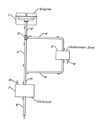
Figure 1 is a schematic view of one embodiment of this invention showing
an internal combustion engine and the process of this invention during the cold
start operation.
~ '
2 ~ a 2
Figure 2 is a 0raph of percent hydrocarbon retention versus ~im~ on which
are presented three plots showing the results for three clifferent molecular sie\t0
adsorbents.
DETAILED DESCRIPTIQN QF Tl-IE INVEhlTlt:)N
Referring now to Figure 1, the engine 1 consists of any internal or cxternal
combustion engine which generates an exhaust gas stream containing noxious
components including unburned or thermally degraded hydrocarbons or similar
organics. Other noxious components usually present in the exhaust gas include
nitrogen oxides and carbon monoxide. The engina may b0 fueled by
hydrocarbonaceous fuel. As used in this specification and in the appended
claims, the term "hydrocarbonaceous fuel" includes hydrocarbons, alcohols and
mixtures thereof. Examples of hydrocarbons which can be used to fuel the
en~ina are the mixtures of hydrocarbons which mak~ up gasolina or diesel fuel.
The alcohols which may be used to fuel engines includ~ ethanol and methanol.
Mixtures of alcohols and mixtur~s o~ alcohols and hydrocarbons can also be
used. Engine 1 may consist of a jet engine, ~as turbine, internal combustion
engine, such as an automobile, truck or bus engine, a diesel engine or the like.The process of this invention is particularly suited for hydrocarbon, alcohol, or
hydrocarbon-alcohol mixture, internal combustion engine mounted in an
automobile. Under the conditions of Figure 1, engine 1 is initially operating at a
relatively reduced temperature, such as a cold engins at startup or warmup whichproduces a relatively high concentration of hydrocarbon vapors (when a
hydrocarbon fuel is used) in the engine exhaust gas stream. When an alcohol is
the fuel, the exhaust stream will contain unburned alcohol.
For oonvenience the description will use hydrocarbon as the fuel ~o exem-
plify the invention. The use of hydrocarbon in the subsequent description is not to
be construed as limitins the invention to hydrocarbon fueled engines.
The engine exhaust gas stream under startup conditions is generally at a
temperature below 500C and typically in the range of 200 to 400C, and con-
30 tains pollutants including high concentration of hydrocarbons as well as nitrogen
oxides and carbon monoxide. Pollutants will be used herein to collectively refer to
any unburned fuel components and combustion byproducts found in th~ exhaust
stream. For example, when the fuel is a hydrocarbon fuel, hydrocarbons, nitro-
gen oxides, carbon monoxide and other combustion byproducts will be found in
, ~
6 ~051~2
the exhaust gas stream. The engine exhaust stream is produced at ~his relativeiylow temperature during the initial period or phase of engine operation, typically for
the first 30 seconds to 120 seconds after startup of a cold engine. The engina
exhaust str0am will typically contain, by volume, 500 to 1000 ppm hydrocarbons.
The engine exhaust stream is flowed through exhaust pipe 2 and through
diverting valvs 3 which directs the stream through exhaust pipc 4 and through
adsorbent zone ~ to provide a first exhaust stream. Adsorbent zone 5 contains
one or more beds of a suitable adsorbent ~or hydrocarbons. The adsorbents
which can be used for the pra~ice of this invention are molecular sieves as char-
1C acterized herein. Hereinafter, the adsorbent bed will be referred to as a molecular
sieve bed. The hydrocarbons and other noxious components are selectively
adsorbed, i.e., preferentially over water, in the molecular sieve bed. In addition to
the molecular sieve bed, the adsorbent zon0 may contain a secondary catalyst
bed in a tandem arrangement with the molecular sieve bed, i.e., immediately aft~r
15 the adsorbent bed. The function of the secondary catalyst bed is to oxidize the
hydrocarbons and carbon monoxide in the exhaust stream. This secondary cat-
alyst is characterized in that it operates at a lower temperature than the primary
catalyst. Bo~h catalysts will be more fully described herein.
The first exhaust stream which is discharged from the adsorbent zone is
2 0 now flowed through exhaust pipe 6 to exhaust pipe 11 and through primary cata-
lyst bed 7 to provide a treated exhaust stream. The function of the primary cata-
lyst is to conver~ the pollutants in the first exhaust gas stream to innocuous com-
ponents. When the engine is fueled by a hydrocarbon, the primary catalyst is
referred to in the art as a ~hree component control catalyst because it can simul-
25 taneously oxidize any residual hydrocarbons presen~ in the first exhaust stream orengine exhaust stream to carbon dioxide and water, oxidize any residual carbon
monoxide to carbon dioxide and reduce any residual nitric oxide to nitrogen and
oxygen. In some cases the primary catalyst may not be required to convert nitricoxide to nitrogen and oxygen, e.g., when an alcohol is used as the fuel. In this30 case the catalyst is called an oxidation catalyst. Because of the relatively low
temperature of the exhaust stream, this primary catalyst does not ~unction at a
very high efficiency, thereby necessitating the adsorbent bed 5. The treated
exhaust stream that is discharged from catalyst bed 7 is then flowed through
exhaust pipe 8 and discharged to the atmosphere. It is understood that prior to
3 5 discharge into the atmosphere the treated exhaust stream may be flowed through
a muffler or other sound reduction apparatus well known in the art.
:
7 2f3~lrj5l~
The temperature at the exit of the adsorbent bed 5 is measured by temper-
ature sensing elernent 9 which typically consists of a thermocouple or other tem-
perature sansing devic0 which transmits an electrical signal to a micrr~processor
located on the engine. At a preset adsorbent bed temperatura usually in the
range of 150C to about 200C, the mieroprocessor sends a message to control
valve 3 thereby completely closing control valve 3, which bypasses adsorbent
zone 5 and allows the sntire engine exhaust stream to be diverted in the second
phase of the process cycle through exhaust pipe 11 and flow through the primary
catalyst bed 7.
e The gas temperature at tha entrance to the primary catalyst bed is mea-sured by another temperature sensing element 10 which also sends a signal to
the same microprocessor. At a preset catalyst gas inlet temperature from sensor
10 when the primary catalyst reaches ItS operatiny temperature, which is typically
in the range of 350 to 400C the microprocessor sends a signal to valve 3 to
partially open valve 3 such that in the third phase of the cycle a minor portion of
the engine exhaust stream is flowed through exhaust pipe 4, through adsorbent
zone 5 and then through the primary catalyst bed 7 while the major portion of the
engine exhaust stream from valve 3 is flowed through exhaust pipe 11 and then
through the primary catalyst bed 7.
The minor portion of the now hot engine exhaust gas stream which flows
through adsorbent zone 5 desorbs the hydrocarbons and any nitric oxide and
carbon monoxide (pollutants) adsorbed on the adsorbent bed to provide a sec-
ond exhaust stream and which flows through exhaust pipes 6 and 11 to the pri-
mary catalyst bed 7 where the pollutants are converted to innocuous compounds
25 to provide a treated exhaust stream which is then discharged to the atmosphere
via exhaust pipe 8. After a period of time in which substantially all the pollutants
are desorbed from the adsorbent bed, (by substantially is meant at least 95% of
the pollutants), generally about 3 to about 5 minutes, the microprocessor sends a
signal to control valve 3 to initiate the fourth phase of the cycle and divert all the
3 o en~ine exhaust stream directly over the primary catalyst bed 7 via exhaust pipe 11
to provide a treated exhaust stream which is then discharged to the atmosphers
via exhaust pipe 8. Instead of waiting for a predetermined time, valve 3 may be
closed~ i.e., divert all the engine exhaust stream over catalyst bed 7, when thetemperature measured by sensor 9 reaches a temperature of 650C.
The adsorbent which is used in adsorbent zone 6 is a molecular sieve
which has a high selectivity for hydrocarbon versus water. in par~icular, the
8 ~ rj~
molecular sieves which can be used in this invention have the following charac-
teristics. 1) a framework Si:AI ratio of at least 2.4:1; Z) are hydrotherrnally stable
and 3) have a hydrocarbon selectivity taH~H2) greater than 1Ø By hydrother-
mally stable is meant the ability of the molecular sieve to maintain its str~Jcture
5 after thermal cycling in tha exhaust gas stream. One method of measuring
hydrothermal stability is to look at the temperature at which 50/O of the structure is
decomposed after heating for 16 hours in air. The temperature is referred to as
T(50). Accordingly, as used in this application, by hydrothermally stable is m~ant
a molecular sieve which has a T(50) of at least 750C. The hydrocarbon selectiv-
10 ity ~ is defined by the following cquation:
C~HC-H20 = XHC . ~H20]
H20 ~HC]
XHc = the hydrocarbon co-loading on the molecular sieve in equilibrium with
the hydrocarbon water vapor mix~ure in the gas phase over the zeolite adsorbent;
XH;~o = the water co-loading on the molecular sieve in equilibrium with the water
2 o and hydrocarbon vapor mixture in the gas phase over the molecular sieve adsor-
bent;
[H2O] = the concentration of water vapor in the exhaust gas stream; and
[HC] = the concentration of the hydrocarbon species in the exhaust gas.
The above definitions show that the selectivity of molecular sieves for
25 hydrocarbons over water is dependent upon the exhaust gas stream tempera-
ture, the particular hydrocarbon species of interest and the relative concentrations
of water vapor and hydroearbon.
In order to calculate XHc and XH2o one needs to first de~ermine the intrin-
sic adsorption strength of the molecular sieve. Intrinsic adsorption strength can
30 be described by reference ~o the Dubinin Polanyi model for adsorption. The
model says that the sorption expressed as the volume of the sorbent structure
occupied by the sorbate is a unique function of the Gibbs Free Energy change on
adsorption. Mathematically this relationship takes the form of a Gaussian distri-
bution with Gibbs free energy chan~e as follows:
X = Liq. dens * VC) * exp(-B * G~G~
where X is the loading expected, VO is the pore volume (cc/g), B is a constant
9 2 (3 .~ 2
that is dependent on the sorbent and sorbate, and G is the Gibbs Free Energy
chan~e. The product of liquid density and VO equates to the saturation loading,
XO, for any pure compound by the Gurvitsch Rule (see Breck, Zeolite Molecular
Sieves, page 426.)
For ideal gases G = RT In (P/P).
The constant B is then inversely relat~d $o the intrinsic adsorption strength. For
example, if the hydrocarbon is b~nzene, a vaiua of B of 0.04 for both benzene and
water gives good results. The estimates of water and hydrocarbon co-loadirl~s
are made in the following way:
1) each individual component loadinç~ is estimated by use of the Dubinin
Polanyi model as outlined above. For each compound present one needs
to know the liquid phase density (approximating the sorbed phase den-
sity), the vapor pressure as a function of temperature, and the actual con-
centration of the species in the gas.
2) Once each pure component loading is calculated, the function ~ is cal-
culated as,
= X/XO/(1 - X/XO)
where X/XO is the loadin~ ratio or fraction of the pore volume filled by each
component if it were present alone. q~ then represents ~he ratio of occu-
2 o pied pore volume to unoccupied porc volume.
3) The co-loadings are then calculated, accounting for each species pre-
sent, by the formula,
XmC=XO*~ /(1 +~
Xmc is the co-loading of each component on the z001ite. This procedure
follows the Loadin~ Ratio Correlation, which is described in
"Multicomponent Adsorption Equilibria on Molecular Sieves", C.l\/l. Yon and
P.H. Turnock AICHE Symposium Series, No. 117, Vol. ~7 (1971).
Both natural and syn~hetic molecular sieves may be used as adsorbents.
Examples of natural molecular sieves which can be used are faujasites, clinoptilo~
lites, mordenites, and chabazite. Examples of synthetic molecular sieves which
can be used are silicalite, Zeolite Y, ultrastable zeolite Y, ZSM-5. Of course mix-
tures of these molecular sieves both natural and synthetic can be used.
~O~j~)'2
The adsorbent bed used in the instant invention can be conveniently
employed in particulate form or the adsorbent, i.~., molecular sieve, can be
deposited onto a solid monolithic carrier. When particulate form is desired, theadsorbent can be formed into shapes such as pills, pellets, granules, rings,
5 spheres, etc. In the employment of a monolithic form, ~ is usually most conve-
nient to employ the adsorbent as a thin film or coating deposited on an inert car-
rier material which provides the structural support ~r the adsorbent. The inert
carrier material can be any r0fractory material sucn as ceramic or metallic materi-
als. It is desirable that the carrier material be unreactive with the adsorbent and
o not be degraded by the gas to which it is exposed. Examples of suitab!e ceramic
materials include sillimanite, petalite, cordierite, mullite, ~ircon, zircon mullite, spo-
dumene, aiumina-titanate, etc. Additionally, metailic materials which are within the
scope of this invention include metals and alloys as disclosed in U.S. Patent No.
3,920,583 which are oxidation resistant and are otherwise capabie of withstanding
15 high temperatures.
The carrier material can best be utilized in any rigid unitary configuration
which provides a plurality of pores or channels extending in the direction of gas
flow. It is preferred that the configuration be a honeycomb configuration. The
honeycomb structure can be used advantageously in either unitary form, or as an
20 arrangement of multiple modules. The honeycomb structure is usually oriented
such that gas flow is generally in the same direction as the cells or channels of the
honeycomb structure. For a more detailed discussion of monolithic structures,
refer to U.S. Patent Nos. 3,785,998 and 3,767,453.
The molecular sieve is deposited onto the carrier by any convenient way
25 well known in the art. A preferred method involves preparing a slurry using the
molecular sieves and coating the monolithic honeycomb carrier with the slurry.
The slurry can be prepared by means known in the art such as combining the
appropriate amount of the molecular sieve and a binder with water. This mixture
is then blended by using means such as sonification, milling, etc. This slurry is
used to coat a monollthic honeycomb by dipping the honeycomb into the slurry,
removing the excess slurry by draining or blowing out the channels, and heating
to 100C. If the desired loading of molecular sieve is not achieved, the above
process may be repeated as many times as required to achieve the desired
loading.
The size of the adsorbent bed is chosen such that at least 40% of the
hydrocarbons in tha exhaust stream discharged from the engine is adsorbed.
11 2f3 jl~i52
Generally, this means that the size of the adsorbent bed varies from 1 to 3 liters.
When the adsorbent is deposited on a monolithic honeycomb carrier, the amount
of adsorbent on the carrier varies from 100 to 450 grams. It is dssirable to
optimize the volume of the adsorbent bed such that the primary catalyst
5 downstream from the adsorbent bed is heated as quickly as possible while at the
same time ensuring that at least 40% of the hydrocarbons in th~ exhaust stream
are adsorbed on the adsorbent bed. It is preferred that th~ adsorbent be
deposited on a monolithic honeycomb carrier in order to minimize the size of theadsorbent bed and the back pressure exerted on the engine.
Instead of depositing the molecular sieve onto a monolithic honeycomb
structure, one can take the molecular sieve and form it into a monolithic honey-comb structure.
The adsorbent which is a molecular sieve may optionally contain one or
more catalytic metals dispersed thereon. The metals which can be dispersed on
15 the adsorbent are th~ noble metals which consist of platinum, palladiurn, rhodium,
ruthenium, and mixtures thereof. The desired noble rnetal may be deposited onto
the adsorbent, which acts as a support, in any suitable manner well known in theart. One example oF a method of dispersing the noble metal onto the adsorb~nt
support involves impregnating the adsorbent support with an aqueous solution of
20 a decomposable compound of the desired noble metal or metals, drying the
adsorbent which has the noble rnetal compound dispersed on it and then calcin-
ing in air at a temperature of 400 to 500C: for a tima of 1 to 4 hours. By
decomposable compound is meant a compound which upon heating in air gives
the metal or metal oxide. Examples of the decomposable compounds which can
25 be used are set forth in U.S. Patent, No. 4,791,091 which is incorpora~ed by
reference. Preferred decomposable compounds are chloroplatinic acid, rhodium
trichloride, chloropalladic acid, hexachloroiridate (IV) acid and
hexachlororuthenate. It is prefer~ble that the noble metal be present in an
amoun~ ranging from 0.01 to 4 weight percent of the adsorbent support.
30 Specifically, in the case of platinum and palladium the range is 0.1 to 4 w~ight
percent, while in the case of rhodium and ruthenium the range is frorn 0.01 to 2weight percent.
These catalytic metals are capable of oxidizing the hydrocarbon and car-
bon monoxide and reducing the nitric oxide components to innocuous products.
3 5 Accordingly, the adsorbent bed can act both as an adsorbent and as a catalyst.
12 20~1~ )2
The primary catalyst which is used in this invention is selected from any
three component control or oxidation catalyst well known in the art. Examples ofprimary catalysts are those described in U.S. Patent Nos. 4,528,279; 4,791,091;
4,760,044; 4,868,148; and 4,868,149, which are all incorporated by reference.
5 Preferred primary catalysts well known in the art are those that contain platinum
and rhodium and optionally palladium, while oxidation catalysts usually do not
contain rhodium. Oxidation catalysts usually contain platinum and/or pallatlium
metal. These catalysts may also contain promoters and stabilizers such ~s bar-
ium, cerium, lanthanum, nickel, and iron. Th~ noblo metals and promoters and
l0 stabilizers are usually deposited on a support such as alumina, silica, titania, zir-
conia, alumino silicates, and mixtures thereof with alumina being preferred. Theprimary catalyst can be conveniently employed in particulate form or the catalytic
composite can be deposited on a solid monolithic carrier with a monolithic carrier
being preferred. The particulata form and monolithic form of the primary catalyst
15 are as described for the adsorbent abovs.
Another embodiment of ~he invention is an adsorbent bed in a tandem
arrangement with a secondary catalyst bed, i.e., immediately after the adsorbentbed. This secondary catalyst bed will contain a catalyst which is different from the
primary catalyst. This secondary catalyst has the characteristic that it can
20 function more effectively at lower temperatures. Also its major function is to
convert hydrocarbons and carbon monoxide to carbon dioxide and water. Addi-
tionally, since the secondary catalyst will not be exposed to high temperatures, it
is not necessary that the secondary catalyst be stable at high temperatures, e.g.,
greater than 700C.
These catalysts are known in the art and usually comprise platinum and/or
palladium dispersed on a high surface area support such as a gamma alumina.
Promoters such as lanthanum, cerium, e~c. may be added to the catalyst. This
secondary catalyst can be either in particulate form or can be deposited onto a
solid monolithic carrier as described above for the primary catalyst. The methods
used to prepare this secondary catalyst are anatogous to those described for
preparing a three component control or oxidation catalyst.
The following examples are presented in illustration of certain aspects of
this invention and are not intended as undue limitations on the generally broad
scope of the invention as set out in the appended claims.
,
!
2 0 ~ 2
~3
EXAMPLE 1
A slurry was preparad using Y 54 and Ludox AS-40 binder. Y-54 is an
ultrastable sodium Y zeolite with a SiO2/A1203 ratio of 5, an Ao of 24.6&~ and aNa/AI ratio of 0.93. Ludox AS-40 is an ammonium stabilized colloidal silica
containing 40 weight pereent solids with 20 micron spherical SiO2 particles and i~
available from DuPont Corp. To 141 grams of distilled water, there was ~dded
100 grams of Ludox AS-40. To this mixture thera were added 191 grams of Y-54
zeolite and then 551 grams of water. This mixturs was sonifled for 10 minutes
using a Sonlfier Cell Disruptor 350.
A ceramic monolithic honeycomb carrier manufactured by Corning Glass
Works measuring 28 mm in diameter by 50 mm in length was dipped into the
slurry, pulled o~t and allowed to drain. The wee honeycomb was air dried and
then heated at 100C for 1 hour. The monolith contained 4.1 grams of z001ite
plus binder. This sample was designated sample A.
EXAMPLE 2
A monolithic honeycomb was prepared as in Exampla 1 except that the
adsorbent used was Y-84. Y-84 is the ammonium form of stabilized Y zeolite with
an Ao of 24.55A, an NH4/AI of 0.3 and a Na/AI of less than 0.01. This sample
contained 4.2 grams of zeolite plus binder and was designated sample B.
EXAMPLE 3
A monolithic honeycomb was prepared as in Exampl~ 1 except that thc
adsorbent used was SA-15. Sa-15 is a steamed form of Y-84 with an Ao of 24.2~
and NH4/AI and a Na/AI ratio of less than 0.01. This sample containEd 5.5
grams of zeolite plus binder and was designated sample C.
EXAMPLE 4
Samples A, B and C were tested to determine their hydrocarbon adsorp-
tion properties by using the following test procedure. The sample to be tested,
measurin~ 28 mm in diameter by 50 mm in length and having a volume of 30.8 cc
was placed in a tubular glass reactor. Over this adsorbent bed there was flowed
30 a gas stream containin~ 998 ppm of propylene, 17,570 ppm of water and the
:
~ ;
14 7~5~
remainder nitrogen. The test was run by starting with a cold (room temperature~
adsorbent bed and gas stream flowing the gas stream at a flow rate of 7 StandardLiters Per Minute (SLPM) over the adsorbent while heating the ~as stream from
25C to 360C in approximately 400 seconds.
The hydrocarbon retention was calculated by integrating the differenc~
between the instantaneous mass flow of hydrocarbons into and out of the adsor-
bent. The percentage of the hydrocarbons r etained was calculated by dividing
the net hydrocarbon retention by the integral of the hydrocarbons flowed into the
bed. Plots of hydrocarbon retention versus time for samples A, B and C are pre-
o sented in Figure 2.
The results presented in Figure 2 show that sample A has the largest initial
value of hydrocarbon retention, but the retention falls off quickly. Samples B and
C have lower initial retention but fall off more slowly with sample B being the best.
It is clear from this test that any of the three zeolites tested can be used to s~lec-
tively adsorb hydrocarbons during tha cold-start phase of an automobile engine.