Language selection

Search

Patent 2051588 Summary

Third-party information liability

Some of the information on this Web page has been provided by external sources. The Government of Canada is not responsible for the accuracy, reliability or currency of the information supplied by external sources. Users wishing to rely upon this information should consult directly with the source of the information. Content provided by external sources is not subject to official languages, privacy and accessibility requirements.

Claims and Abstract availability

Any discrepancies in the text and image of the Claims and Abstract are due to differing posting times. Text of the Claims and Abstract are posted:

  • At the time the application is open to public inspection;
  • At the time of issue of the patent (grant).
(12) Patent Application: (11) CA 2051588
(54) English Title: SUPPORTING FRAME WITH COUNTERWEIGHT FOR A SURGICAL MICROSCOPE
(54) French Title: BATI-SUPPORT A CONTREPOIDS POUR MICROSCOPE MEDICAL
Status: Dead
Bibliographic Data
(51) International Patent Classification (IPC):
  • G02B 21/24 (2006.01)
  • F16M 11/04 (2006.01)
  • G02B 7/00 (2006.01)
(72) Inventors :
  • HELLER, RUDOLF (Switzerland)
(73) Owners :
  • HELLER, RUDOLF (Not Available)
  • CARL-ZEISS-STIFTUNG, A FOUNDATION ESTABLISHED UNDER THE LAWS OF GERMANY TRADING AS CARL ZEISS (Germany)
(71) Applicants :
(74) Agent: ROBIC
(74) Associate agent:
(45) Issued:
(22) Filed Date: 1991-09-17
(41) Open to Public Inspection: 1992-03-20
Availability of licence: N/A
(25) Language of filing: English

Patent Cooperation Treaty (PCT): No

(30) Application Priority Data:
Application No. Country/Territory Date
G 90 13 260.2 Germany 1990-09-19

Abstracts

English Abstract


ABSTRACT OF THE DISCLOSURE:
Disclosed for a supporting frame for a surgical microscope is a device for
balancing the weight, said device comprising a hinge parallelogram which
can be pivoted about a pivot bearing and consists of two movably mounted
weight. Said device permits continuous balancing of the weight of the
surgical microscope.


Claims

Note: Claims are shown in the official language in which they were submitted.

Claim:
Supporting frame for a spatially adjustable surgical microscope (14) which
can be locked in any position, comprising a unit-supporting part configured
as a coupled hinge parallelogram (2), which said unit-supporting part is
connected with an intermediate support part (3) which, in turn, is connected
with a vertical support column (4) and can be adjusted relative thereto,
characterized in that the intermediate support part is configured as a hinge
parallelogram (3), of which one side is configured as a two-armed lever (3a)
which can be rotated in a pivot bearing (6) connected with said support
column (4); that the side opposite the lever (3a) is configured as a rod (3b)
on which an counterweight (G2) is mounted in an axially movable manner;
that the connecting hing (9) of the lever (3a) on the adjacent side (3c) of
(G1) which can be moved parallel to the side (3c) of the parallelogram,
while the connecting hinge (7) of the lever (3a) on the adjacent side (3d) of
the parallelogram is connected with the unit-supporting part (2) configured
as coupled hinge parallelogram.


Description

Note: Descriptions are shown in the official language in which they were submitted.


~(J5~X`~


Sup~ortin~ F! qme wi th -r-- oun~er~eigh~ fdr a Surgical ~licl-oscoDe

The in~ention relstes to a supporting ~rame ~or 8 spati~lly sdjusla~ls
surgical microscope which can be locked in 9ny positiQn, whic17 consists of a
unil.-supporting part configured as ~ cdupled hin~e parallelo~r~m wllich is
eoupled wit.h ~n interlnediate supporl.ing p~r~ w~lich, in ~urn, is c~r,nected
with a ~ertical supp~rt column ~nd c~n be adjusted relslive to said support
column.

5uch support.ing fr~mes are me~nt to permit ~ sur~eon to adjust and fix in
positicn 8 surgical microscope d~pending on position and orientation in a
predetermined sp9ti31 zone without impail-ing his su1 gicsl scthity. In
psrlicular, it should be pl~ssible ~or ~.I)e ~urgeon to ~d~ust sueh supportill~
fr~mes without requiring strength which Would impair his aclivity. In ordel-
lo atlsin the desired mobility of the surgicsl microscope requiring 8
minimum of strength on the p3rt of the surgeon, lt is necessary that the
we~ght of the surglcal microscope to ~e moved ~s bs1anced by 9
counterweight.

In the case of c known supporting ~rame of this type as d~scribed, e.g, in DE
P~lent 23 20 266 the wei~ht or lhe surgical microscope is b~lsnced in th~l
exchangeable ond ~xially sd~ust~ble weights are provir~e~ ~n ~n intermediate
support and on ~ leYer system. Exchangil1~ ~r sssem~l~n~ ~nd dis~ssembling
of weight~, however, is not user-fl-iendly snd therefore does not meet the
requlrements expected o~ modern surg~c~l eQu~pmenl.

The in~Qntion herein is me~nt to eliminste this problem.

Th~ Inven~lon h~s ~ ed tllls pr~blem ln lh~t the intel-medi~te suppot-tin~
p~rt is conftgured as ~ hinge parallelo~r~m ~Yin~ one si~e configured as


2~515'88
t'.A~O-arlned le~er whic.~l can be rota~d in 9 be~l-ing conllected Wit~l the
support co~u~on th3l tl~e side opposi~e l~e le~ e.r is confiyu-ed 9S a rod to
which a mov~L~le counterweigl~t is mounted ~lat the conneoting hinge o~ lhe
rod on the adj~cent side of t~ par~llelogram co~nprises ~ lever system for
an~ther counterweigh~ Y~hile l~le connel ting ~linge of the lever on its
adjacent si~e of the par31lelQgrsm ia connscted with the unit-~upporting
p~rl conf~gured as coupled ~linge p~r~lle~ogram.

The sdvantages w~lich can ~e at~ined in accor~ance with the inYen~ion
herein consist in p~r~iculsr in t~lat the weight or tile surgical microscope
can be b~lanced oplimnlly because t~e coun~erweights can be shifled
continuously snd in th~t ~he msnnQr ot balcncing tlle weigl~t is user-friendl~
because odditionol weights need not be screwed on or of 1.

Tlle drswing ~how~ ~n exam~le of embodiment of ~he in~entio~ erein an~l is
explained in detail herein~ltel-.

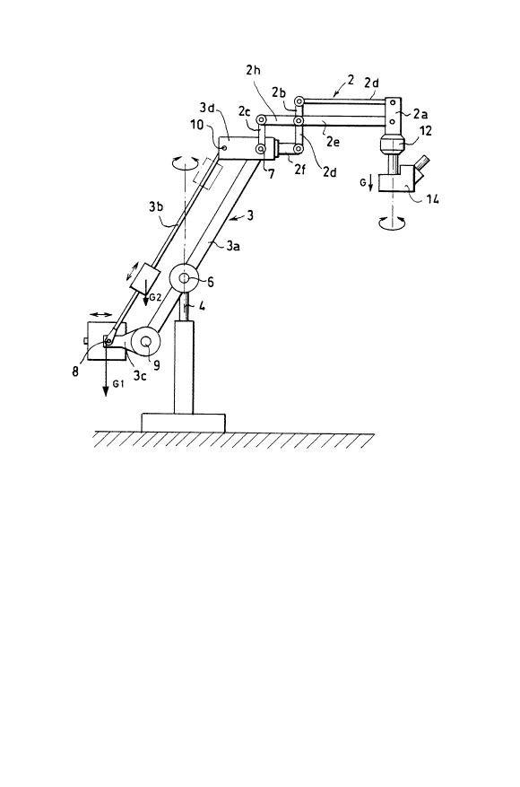
Figùre 1 ~s a schematic illustr~tion o~ a side elev~tion of the in\rentilre
supportlng frcme

Figure 2 is a schemstic perspeotive illustration of h~w the
counterweigh1. (~1) is mounted;

Figures 3 show the principle o~ balsncing the weigh~ of the surgical
~nd 4 microscope.

Figure I shows the hel9ht-ad)ustsble support column (4) Or the supporting
frame. ~aid supporting frame ~s connected ~i~ a pi-~o~ ~e~ring ~) with a
hingQ parallelogram ~3}. One side of ssid hingQ parallelogram (3) is
conflgured ~s ~ two-armed lever (3a) which can be ro~ted in said pil/ol
~earitlg (~). The side opposite the lever (3a) is configul-ed os a r~ ~3b~
which supporls ~ weight ~G2) which can be s~ ted in axial direction as
indic~ted by the 3rr~w. The connec~ing hinge ~ of the level- ~3a) comprises
p~rallel ~o the side ~c) of the p~r~llelogr3m snoaher coun(erweigh~ ~Glj
which c~n bc shifled in the direction of lhe arruw ac indicated. The
connecting hinge ~7) o~ the le~er 1~Ja) on arl ad)acent ~ide ~3d) of the

~515~
parallelogram is ~ol~nected wit~ t~e coupled hinge p~rsllelogr~m ~ whieh
supporls the surgic.~l microscope ( 14) ~y me~ns of a piYot be~ring ~12~.

In the support of the counterweigllt ~GI~ shown in Figure 2 in ~ perspective
schem~tic illustr~tion the lever syslem holding the weight has referenoe
number ( 1~). Said weight can be shirted in lhe directiGn 9S indic~ted by the
~rrow. The sides ~nd ioil1ts Qf ~lQ llinge pal~ el0~ ln ~3) WhlCil ~re shown
schemstic~lly have the same reterelloe nun~bers ~s in the illustration of
Figure 1.

Flgures 3 snd 4 sh~w tl~e increment~l balsnc~ng of tlle weight ~G) of the
surgiccl micr~scope ~14) by ~l~e counterweights ~1 and ~ in two positions
of the supporling frame. First, ~le hin~e parallelogram ~3~ is shown a~ by
Figure 3, l.ilted forward, i.e., brouyht into ~1orizonl~1 posilion. This positiQn
is expressed by the e~uation of corlditiol1

G l ~ G2 - Z2 - G - Z

Inssmuch ~s ~he Y~lues ~1, Z 1, G2 and Z sre cons~nt, thel-e is a rorm~l
connection between the weight ot the n~icroscope (G) cnd the lever ~rrn (~)
of the eounterweight ~G2~. The lever ~rm (2~) m~y be adjusted cDntinuousty
for bolsncing.

The second step shown by Figure 4 lskes place with the re-erected
supporting frsme. This position is e~pr~ssed by th~ following equstion of
condition

~1 Xl f G2-X2 ~ G-X

With lhe exception of X I and G llle values or ~his equation cannot be changed.
L~ver ~rm ~Xl~ of the counterwe~ t ~G~) is ~djusted for bal~ncing.

Representative Drawing
A single figure which represents the drawing illustrating the invention.
Administrative Status

For a clearer understanding of the status of the application/patent presented on this page, the site Disclaimer , as well as the definitions for Patent , Administrative Status , Maintenance Fee  and Payment History  should be consulted.

Administrative Status

Title Date
Forecasted Issue Date Unavailable
(22) Filed 1991-09-17
(41) Open to Public Inspection 1992-03-20
Dead Application 1994-03-19

Abandonment History

There is no abandonment history.

Payment History

Fee Type Anniversary Year Due Date Amount Paid Paid Date
Application Fee $0.00 1991-09-17
Registration of a document - section 124 $0.00 1992-12-11
Owners on Record

Note: Records showing the ownership history in alphabetical order.

Current Owners on Record
HELLER, RUDOLF
CARL-ZEISS-STIFTUNG, A FOUNDATION ESTABLISHED UNDER THE LAWS OF GERMANY TRADING AS CARL ZEISS
Past Owners on Record
None
Past Owners that do not appear in the "Owners on Record" listing will appear in other documentation within the application.
Documents

To view selected files, please enter reCAPTCHA code :


To view images, click a link in the Document Description column. To download the documents, select one or more checkboxes in the first column and then click the "Download Selected in PDF format (Zip Archive)" or the "Download Selected as Single PDF" button.

List of published and non-published patent-specific documents on the CPD .

If you have any difficulty accessing content, you can call the Client Service Centre at 1-866-997-1936 or send them an e-mail at CIPO Client Service Centre.


Document
Description 
Date
(yyyy-mm-dd) 
Number of pages   Size of Image (KB) 
Representative Drawing 1999-07-05 1 11
Drawings 1992-03-20 2 26
Claims 1992-03-20 1 27
Abstract 1992-03-20 1 9
Cover Page 1992-03-20 1 16
Description 1992-03-20 3 119