Note: Descriptions are shown in the official language in which they were submitted.
3 ~
WOVEN WIRE BELT
8ACKGROUND OF THE INVEN*ION
-
1. Field o the invention
The present invention relates to a woven wire
S belt, for example, for use as a conveyor bel-t.
The belt is useful particularly in an apparatus
in whi.ch the belt runs over rotatable rollers.
2. Description of the prior art
Belts such as conveyor belts are known in which
the woven wire belt runs in the direction of warp wires
over rotatable rollers. There are wires extending
transversely to the running direction o f the belt which
have lower projections which are offset to protrude beyond
the underside of the woven structure and engage in guide
grooves on the circumference of the rollers.
Woven wire belts of this type are used for the
conveyance of many products, for example of piece goods,
boards, sheets, fabrlcs, which can hereby also be taken
through a treatment liquid, dried or processed in another
way. Whereas the woven wire belt consists of flexible
wires in its longitudinal direction and rigid weft wires in
its transverse direction, which produce a smooth belt
surface, the lower projections offset to protrude beyond
the underside of the woven structure form rows of
projections by which the belt guides itself laterally in
guide grooves of the driving and deflecting rollers.
2 ~
Woven wire belts of this type are known from German paten-t
1 271 624 and German patent 29 00 871 C2.
Althou~h the known woven wire belts can be
produced with a rela-tively l.arge mesh width, they still
offer the products to be conveyed a relatively large
supportin~ area. The transversely running weft wires and,
in the case of certain embodiments, also the warp wires or
the crossing points between weft wires and warp wires leave
impressions in the conveyed product. This is often
undesired and it is often required that the conveyed
product is kept clear from the surface of the woven wire
belt as far as possible or at most is supported at
particular points on the woven wire conveyor belt is often
set.
SUMMARY OF THE INVENTION
Therefore the object of the invention is to
provide a woven wire belt in such a way that it supports
the product to be conveyed on it only at particular points
a~d the actual woven ~tructure of the conveyor belt is
prevented from leaving impressions on the product to be
conveyed.
In accordance with the invention in one aspect,
in a woven wire belt, some of the wires that extend
transversely to the direction oE travel of the belt have
upper projections. Each of these upper projections is
arranged intermediately between two adjacent warp wires.
In this way the upper projections, which May be projections
2 ~
shaped into the transversely extending wires, are offset to
protrude beyond the upper side of the woven structure.
This design has the advantage that it produces on
the woven wire belt spaced-apart, punctiform elevations,
which support the conveyed product at certain points, so
that the conveyed product, for example a metal plate, a web
of sheeting or the like, does not come into c,ontact with
. the woven surface of the conveyor belt.
Such a punctiform support is particularly
advantageous for example when a metal plate or other object
conveyed on the woven wi.re belt has previously been
painted or coated and the paint or the coating is to be
dried or set during conveyance on the woven wire belt by
air which is blown from below through the woven wire belt
onto the conveyed product.
The offset upper projections or humps are also of
advantage when a sheet-like conveyed product, for example a
web of sheeting or fabric, extending between two woven
wire belts according to the invention is to be taken
through a treatment liquid or a powder bath in such a way
that as large a surface as possible of the web taken
throu~h the bath comes into contact with the powder or the
treatment liquid.
The upper projections protruding beyond the
surface of the belt can also serve as carriers for piece
goods transported on the belt, if the belt runs obliquely
upwards or downwards and the product conveyed on the belt
is to be prevented from slipping on the belt surface.
3 ~
In order to maintain the weave at all crossing
points between warp wires and weft wires, i-t is important
that the upper projections are in each case arranged mid--
way between two laterally spaced-apart warp wires and the
wires having the upper projections cannot be displaced
transversely to the running direction of the belt. Such
lateral displacement can be prevented by the lower
projections which thereby serve not only to guide the woven
wire belt in the transverse direction but also to stabilise
the upper projections.
The upper projections may be arranyed laterally
spaced apart at a spacing which corresponds to a multiple
of the warp pitch. They are expediently arranged here in
a plurality of wires extending transversely to the running
direction so as to be one behind the other in a row in the
running direction of the belt. This has the advantage
that in a lower run of a continuous belt the upper
projections can at the same time assume the lateral
g~idance of the belt, if such guidance is necessary, and
they run in ciroumferential ~rooves of supporting rollers
which support the lower run.
In one embodiment of the supporting woven belt
according to the invention, guide wi~es are provided which
are wires woven with the warp wires in between the weft
wires. The guide wires extend transversely to the running
direction of the belt. They may have a flattening, at
least on a side parallel to the pla~e of the belt. The
upper projections can be arranged in these guide wires.
3 ~
Such a design is advantageous in the case of lightweight
woven wire belts with simple linen weave, for which the
lateral guidance is assumed b~ separate guide wires, in
which case the lower projections are also arranged in the
guide wires. In the case of these belts, both the upper
and -the lower projections can be arranged in the guide
wires, the flattening of the guide wires preventing the
guide wires from turning about their longi.tudinal axis and
the offset upper projections being disposed approximately
parallel to the surfaces of the woven wire belt.
In the case of another embodiment of the woven
wire belt according to the invention, the upper projections
are arranged in the weft wires of the woven structure,
which also have the lowér projections which are offset to
lS protrude beyond the underslde of the woven structure. With
this t~pe of woven wire belt, the lower projections
simultaneously serving to produce the weave prevent turning
of the weft wires and keep the upper projections upright,
even if the weft wires, in which the ~Ipper projections are
2~ provided, have a circular cross-section.
It is expedient in both embodiments if upper
projections arranged one behind the other in a row in the
running direction of the belt are spaced apart at a spacing
which corresponds to an integral multiple of the weft wire
spacing. All the wires provided with upper projections
then have an analogous weave and it is ensured that the
upper projections of each row align precisely with one
another in the longitudinal direction.
2 (~ 3 ~
The invention also consists in a conveyor having
a continuous belt as described above, and rollers -to define
the belt path.
BRIEF INTRODUCTION OF THE DRAWINGS
Fur-ther features and advantages of the invention
are given in the following description and the drawing, in
which a preferred embodiment of the invention is explained
in further detail with reference to an exemplary embodiment
and in which:
Fig. 1 shows a woven wire belt according to the
invention in a plan view,
Fig. 2 shows the belt of Fig. 1 in a cross-
section according to line II-II transversely to the running
direction of the belt, with an object conveyed on the belt
indicated, and
Fig. 3 shows the supporting woven belt according
to Fig. 1 in a partial longitudinal section according to
line III-III.
DESCRIPTION OF THE PREFERRED EMBODIMENT
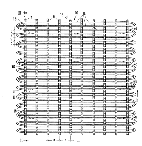
In the drawing, 10 deno~es a supporting woven
belt for a conveying apparatus, of which in Fig. 2 only one
deflecting roller 11, around which the woven wire belt 10
runs, is partially represented. The woven wire belt 10
serves for the conveyance of piece goods, for example
painted car or machine parts, one of which is indicated in
Fig. 2 merely by its lower edge and is denoted by 12.
2 11~3~
The woven wire belt lO represented in the drawing
comprises flexible warp wires 9, which e~tend in the
longitudinal direction or running direction 13 of the belt
and consi..st of thin, intertwisted metal wires, and
relatively stiff, monofilament weft wires 14, which extend
transversely to the running direction 13 and are woven with
the warp wires 9 in linen weave. Each weft wire is
provided with a lower hump or projection 15, offset to
protrude beyond the underside of the woven wire structure
10, wherever it runs underneath a warp wire but is smooth
and straigh-t wherever it crosses over a warp wire 9. As a
result, in the running direction 13 on the underside of the
woven wire belt there are rows of projections, by which the
wo~en wire belt guides itself in groove-shaped channels 16
. which are arranyed laterally spaced apart on the
circumference of the deflecting roller 11. The other
drivin~ and deflecting rollers of the conveying apparatus
have similar channels.
Individual weft wires 14, namely the weft wires
14a, 14b, 14c and 14d, also have upper projections 18,
which are offset to protrude upwardly at the upper side 17
of the woven structure lO and are in each case arranged
mid-way between two laterally spaced-apart warp wires 9.
In this arrangement, in each case two upper projections 18
in one of the weft wires 14a, 14b, 14c and 14d are
laterally spaced apart at a spacing which corresponds to a
multiple of the warp pitch a. In the case of the
embodiment shown, the upper projections 18 have a lateral
2 ~ 5
spacin~ of in each case four times a.
It can be seen from Fig. 1 that the upper
projections 18 in the weft wires l~a to 14d are arranged
one behind the other in several rows in the running
direction 13 of the belt, so that they align with one
another in the running direction. They are spaced apart
in the running direction 13 of the belt lO at a spacing
which corresponds to an integral multiple of the weft wire
spacing b, which in the case of the exemplary embodiment
shown corresponds to eight times this spacing b (Fig. 3).
It can be seen from Fig. 2 that the conveyed
product 12 is supported on the upper projections 18 only at
particular points, whereas the greater part of its lower
surface facing the woven wire belt 10 remains clear. The
lower surface of the conveyed product 12 can therefore
easily be cooled by air which is blown from the underside
of the woven wire belt 10 through its meshes onto the
underside of the conveyed product 12.
In another embodiment, not shown in any more
detail here, the upper projections 18 and also the lower
projections 15 are arranged in special guide wires, which
are woven into the woven wire belt between two weft wires
at a spacing of a multiple of the weft wire pitch b and are
provided at least on one side with a flat-tening. The weft
wires themselves then need not be provided with the lower
projections or upper projections, since the guide wires are
provided with both of these and assume both the lateral
guidance of the woven wire belt and also support -the
2~ ~L~3~i
conveyed product only at particular points on the upper
side of the woven wire belt. The woven wire belt itself
can then be a customary woven wire belt with linen weave.
Such a design is suitable in particular for lightweight,
thin belts, such as are used for the conveyance of webs of
sheeting or fabric and are described in German patent 29 00
871 C2.
The invention is not restricted to the exemplary
embodiments shown and described, but other embodiments are
10 also possible without departing from the scope of the
invention.
For example, the woven wire belt according to the
invention may also be provided with more or fewer upper
projections, and it is also possible to provide a different
weave if advantages are obtained as a result. However, it
is preferable that the weave is present on both sides of
the upper projections.