Language selection

Search

Patent 2052029 Summary

Third-party information liability

Some of the information on this Web page has been provided by external sources. The Government of Canada is not responsible for the accuracy, reliability or currency of the information supplied by external sources. Users wishing to rely upon this information should consult directly with the source of the information. Content provided by external sources is not subject to official languages, privacy and accessibility requirements.

Claims and Abstract availability

Any discrepancies in the text and image of the Claims and Abstract are due to differing posting times. Text of the Claims and Abstract are posted:

  • At the time the application is open to public inspection;
  • At the time of issue of the patent (grant).
(12) Patent: (11) CA 2052029
(54) English Title: DRIVE HEAD FOR A SCISSORS JACK
(54) French Title: TETE D'ENTRAINEMENT D'UN CRIC LOSANGE
Status: Deemed expired
Bibliographic Data
(51) International Patent Classification (IPC):
  • B66F 3/08 (2006.01)
  • B66F 3/12 (2006.01)
(72) Inventors :
  • ENGEL, DARRYL L. (United States of America)
(73) Owners :
  • UNIVERSAL TOOL & STAMPING CO., INC. (United States of America)
(71) Applicants :
(74) Agent: RIDOUT & MAYBEE LLP
(74) Associate agent:
(45) Issued: 1998-06-23
(22) Filed Date: 1991-09-23
(41) Open to Public Inspection: 1992-03-25
Examination requested: 1995-11-29
Availability of licence: N/A
(25) Language of filing: English

Patent Cooperation Treaty (PCT): No

(30) Application Priority Data:
Application No. Country/Territory Date
587,068 United States of America 1990-09-24

Abstracts

English Abstract


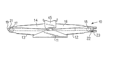
A drive head for the screw of a scissors jack which is
formed in the shape of a wing nut which has a hexagonal socket
formed between opposed walls so that a conventional folding
lug wrench can be used by inserting its hex tube into the
hexagonal socket to drive it. In the event of overload, the
lug wrench will slip relative to the wing nut so as to prevent
excessive loads and stresses upon the jack.


French Abstract

La présente invention porte sur une tête d'entraînement utilisée pour entraîner la vis d'un cric à parallélogramme. La tête d'entraînement a la forme d'un écrou à oreilles comportant, entre ses parois opposées, une douille à six pans creux dans laquelle le tube hexagonal d'une clé à tige pliable classique peut être inséré pour assurer l'entraînement. En cas de surcharge, la clé à tige glissera en fonction de la position de l'écrou à oreilles, de manière à prévenir les charges et les tensions excessives sur le cric.

Claims

Note: Claims are shown in the official language in which they were submitted.


The embodiments of the invention in which an exclusive
property or privilege is claimed are defined as follows:
1. A scissor jack formed with a base and two pair of
lower links with first ends pivotally attached to said base,
a lifting cap and two pair of upper links pivotally attached
to said lifting cap, second ends of one pair of said lower
links pivotally attached to second ends of one pair of said
upper links, second ends of another pair of said lower links
pivotally attached to second ends of another pair of said
upper links, a threaded collar mounted on the pivot of the
second ends of said one pairs of upper and lower links, a
thrust bearing mounted on the pivot of said second ends of
said other pairs of said upper and lower links, a threaded
shaft receivable through said thrust bearing and threadedly
received in said threaded collar, and a thumb screw attached
to the end of said threaded shaft adjacent said thrust bearing
for turning said threaded shaft so as to raise and lower said
jack, wherein said thumb screw is formed with an opening into
which a lug wrench can be inserted so as to turn said threaded
shaft, and wherein said thumb screw is formed with flexible
walls about said opening so that said lug wrench can turn
relative to said threaded shaft under overload conditions.
2. A scissor jack according to claim 1 wherein said
thumb screw is formed with a first planar member which is
attached to the end of said threaded shaft, a pair of handle
members attached to said first planar member and formed with
end portions which are parallel to each other and with center
portions which form a wrench receiving portion.
3. A scissor jack according to claim 2 wherein said
wrench receiving portion forms a generally hexagonal opening
for receiving said lug wrench which has a hexagonal portion.


- 5 -

4. A scissor jack according to claim 3 wherein overload
torque causes said wrench receiving portion to deform so that
said hexagonal portion of the lug wrench turns in the
hexagonal opening of said wrench receiving portion.


- 6 -

Description

Note: Descriptions are shown in the official language in which they were submitted.


2 ~ 2 ~
S P E C I F I C A T I O N
This invention relates in ~eneral to a scissors jack and
in particular to an improved drive mechanism.
UO S. Patent No. 4,802,653 illustrakes a scissors-type
jack which can be raised and lowered with a folding lug wrench
which has a handle that is pivotally connected to a tube that
has a hexagonal opening and a hexagonal outer contour. In
such jacks, the hexagonal tube fits over the hexagonal hex
head on a threaded screw such that as the threaded screw is
rotated with the lug wrench, the jack can be raised and
lowered.
The hex head of the screw is the same size as the lug
nuts and the hex tube of the folding lug wrench fits over the
hex head of the screw.
With such prior art scissors jack, it is possible to
overload the jack by exerting too much torque on the hex head
of the threaded screw of the jack so as ~o bend or break the
jack.
It is an object of the present invention to provide a
novel drive head for the drive screw of a scissors jack.
It is a feature of the present invention to provide a new
drive head for a scissors jack which is provided with a socket
into which the outer diameter of a hex-shape tube of a folding
lu~ wrench can be received so as to raise and lower the jack.
The new drive head is in the general shape of a wing nut which
can be operated by the users fingers so as to raise the jack
until it engages the vehicle after which the folding lug
wrench is used. When lowering the vehicle, the jack is
unloaded and the user can then use his fingers to finish the
lowering the jack into its storage position.


-- 1 --

2 ~
The hex tube of the folding lug wrench slips inside the
hex wing nut so as to turn the screw of the jack and with the
novel design of the invention if the jack is overloaded the
hex wing nut will spread open and the hex tube of the folding
lug wrench will slip without turning the jack drive screw.
Thus, the present invention prevents the jack from being
overloaded. Even though the hex tube slips in the hex wing
nut, the jack will still be functional and the present
invention provides a jack with a non-destructive failure mode
so as to prevent the jack from being overloaded. This is an
important safety factor, since overloadiny the jack is
dangerous.
Other objects, features and advantages of the invention
will be readily apparent from the ~ollowing description of
certain preferred embodiments th~ereof tak~n in conjunction
with the accompanying drawings although variations and
modifications may be effected without departing from the
spirit and scope of the novel conc:epts of the disclosure, and
in which:
ON THE DRAWINGS:
FIG. 1 is a side elevational view of the jack of the
invention;
FIG. 2 is a top elevational view of the jack of the
invention:
FIG. 3 is a perspective Yiew of the drive screw with the
novel wing nut head attached thereto;
FIG. 4 is a sectional view showing the hex lug wrench
enyaged with the wing nut; and
FIG. 5 is a sectional view taken on line V-V of FIG. 4.
FIGS. 1-5 illustrate the invention which comprises a
novel drive head for a scissors jack. FIGS. 1 and 2, for
example, are respectively the side plan and top plan view of

2 ~ 2 ~
a scissors jack in which the novel drive head has been
installed. As shown in Patent 4,802,653, a scissors jack has
a base 11 with two pair of lower pivot arms such as 12 and 13
illustrated in FIG. 1 which are pivotally connected by pivot
pins 17 and 18 to two pair of upper sci~sor arms 14 and 16 and
30 and 35. A load carrying member 45 is pivotally connected
to the upper arms such as shown in FIGS. 1 and 2. A thre~ded
msmber 21 is received on pivot pin 17 and threadedly receives
a bolt shaft 19 which lowers and raises the jack. FIG. 3
illustrates the bolt 19 which has a threaded portion 25
adiacent one end and a non-threaded portion 26 adjacent the
other end and has the novel drive head 23 connected to the
other end. The novel drive end 23 is in the form of a thumb
screw which can be manually manipulated by a user and has a
back plate 27 which is welded or otherwise attached to the end
of the shaft 19 adjacent the portion 26. A generally
hexagonal opening i5 Eormed by members 34, 36 and 29 and 31
which are spaced from each other as shown. A horizontal
extending portion 37 extends from portion 36 and a horizontal
portion 33 extends from portion 34. A horizontal portion 28
parallel to portion 37 extends from portion 29 and a
horizontal portion 32 extends from portion 31 and is parallel
to portion 33. Portions 28, 32, 33 and 37 with the center
hexagonal portion of the drive head 23 form a thumb screw
which can be turned manually by an operator to raise the jack
when it is not under load and to lower and close the jack for
storage.
~IG. 4 illustrates a handle 41 which has a first lever
portion 40 which is pivotally connected by a pivot pin 42 to
a hex tube 43. The hex tu~e ~3 has an insidP diameter which
is oE the same size as the hex nut on the end of the drive
screws for conventional jacks such as shown in Patent

,2 ~
4,802,653. In use with such conventional jacks, the hex head
of the screw is received inside the hex tube 43 so that it can
be driven by rotating the wrench 41 with the handle 40. In
the present invention, the opening formed in the wing nut-
shaped handle 23 between the portions 29, 31, 34 and 36 is
such that tha outside diameter o~ the hex tube 43 fits in the
wing nut 23 as shown in ~IGS. 4 and 5, for example, so that
the wrench 41 can be used to raise and lower the jack.
However, in the presPnt invention, the torque which is applied
to the drive screw l9 is limited because an excessive torque
will cause the hex tube 43 to slip inside the hex wing nut 23
so that the shaft. 19 will not be rotated under such conditions
of excessive loadO
With the invention, if the jack is overloaded, the hex
wing nut 23 will spread open so that the members 29 and 31
move away from the members 34 and 36 and the hex tube 43 will
slip out of the wing nut 23. However, such overload does not
render the jack nsn-functional in that when the overload i5
removed, the hex tube 43 can be used to drive the bolt lg
without slipping.
It is seen that this invention provides a new and novel
drive head for the drive screw of a scissors-type jack and
although the invention has been described with respect to
preferred embodiments, it is not to be so limited as chan~es
and modifications can be made which are within the full
intended scope of the invention as defined by the appended
claims.

Representative Drawing
A single figure which represents the drawing illustrating the invention.
Administrative Status

For a clearer understanding of the status of the application/patent presented on this page, the site Disclaimer , as well as the definitions for Patent , Administrative Status , Maintenance Fee  and Payment History  should be consulted.

Administrative Status

Title Date
Forecasted Issue Date 1998-06-23
(22) Filed 1991-09-23
(41) Open to Public Inspection 1992-03-25
Examination Requested 1995-11-29
(45) Issued 1998-06-23
Deemed Expired 2001-09-24

Abandonment History

There is no abandonment history.

Payment History

Fee Type Anniversary Year Due Date Amount Paid Paid Date
Application Fee $0.00 1991-09-23
Registration of a document - section 124 $0.00 1992-04-16
Maintenance Fee - Application - New Act 2 1993-09-23 $50.00 1993-07-28
Maintenance Fee - Application - New Act 3 1994-09-23 $50.00 1994-09-16
Maintenance Fee - Application - New Act 4 1995-09-25 $50.00 1995-09-19
Maintenance Fee - Application - New Act 5 1996-09-23 $150.00 1996-07-05
Maintenance Fee - Application - New Act 6 1997-09-23 $150.00 1997-09-16
Final Fee $300.00 1998-02-26
Maintenance Fee - Patent - New Act 7 1998-09-23 $150.00 1998-08-18
Maintenance Fee - Patent - New Act 8 1999-09-23 $150.00 1999-09-23
Owners on Record

Note: Records showing the ownership history in alphabetical order.

Current Owners on Record
UNIVERSAL TOOL & STAMPING CO., INC.
Past Owners on Record
ENGEL, DARRYL L.
Past Owners that do not appear in the "Owners on Record" listing will appear in other documentation within the application.
Documents

To view selected files, please enter reCAPTCHA code :


To view images, click a link in the Document Description column. To download the documents, select one or more checkboxes in the first column and then click the "Download Selected in PDF format (Zip Archive)" or the "Download Selected as Single PDF" button.

List of published and non-published patent-specific documents on the CPD .

If you have any difficulty accessing content, you can call the Client Service Centre at 1-866-997-1936 or send them an e-mail at CIPO Client Service Centre.


Document
Description 
Date
(yyyy-mm-dd) 
Number of pages   Size of Image (KB) 
Cover Page 1993-11-27 1 15
Abstract 1993-11-27 1 14
Claims 1993-11-27 2 63
Drawings 1993-11-27 1 47
Description 1993-11-27 4 186
Cover Page 1998-06-16 1 36
Representative Drawing 1998-06-16 1 6
Fees 1999-09-23 1 29
Correspondence 1998-02-26 1 36
PCT Correspondence 1996-01-15 1 49
Office Letter 1996-01-04 1 50
Prosecution Correspondence 1995-11-29 1 28
Examiner Requisition 1996-02-27 2 41
Fees 1996-07-05 1 32
Fees 1996-01-15 1 46
Fees 1995-09-19 1 29
Fees 1994-09-19 1 34
Fees 1993-07-28 1 25