Note: Descriptions are shown in the official language in which they were submitted.
2 ~ ~ ~
IODINE RESIN/CARBON WATER PURIFICATION SYSTEM
BACKGROUND OF THE INVENTION
The present invention relates to water purification
and filtration systems and, in particular, to a system
including an iodine resin purification bed.
Along with expanding populations and
industrialization has come an ever expanding problem of
water pollution, either by way of chemical or microbial
contaminants (i.e. bacterial, viral or parasitic).
Natural sources of potable drinkable water are
proportionately decreasing, thus requiring various
processing treatments to make the water consumable.
Varieties of techniques have been developed in the
latter regard at the bulk treatment levels for large
populations, as well as for small volumes for an
individual or household. These methodologies may include
varieties of mechanical treatment systems and/or chemical
treatments, but which systems suffer from various
shortcomings. For example, distillation systems, while
producing substantially contaminant free re-constituted
water, does so at the loss of naturally occurring
minerals. These systems are also slow and require large
amounts of energy. Chemical treatment systems,
similarly, are costly and/or leave residual tastes in the
treated water.
Filtration systems and, in particular, granulated
active carbon (GAC) systems, otherwise, economically
remove a wide variety of relatively small contaminants.
The beds do not however remove various viral and
bacterial contaminants which can collect and grow within
the carbon beds, thus necessitating the re-charging of
the beds or costly treatment thereof to remove the
undesired contaminants. Agencies responsible for large
installations, as well as approval regulators for smaller
installations, have accordingly begun to withhold
approval for such systems.
.
. : ~ ,
: .: , : . :~
.
~. :
One approach in the small volume treatment market
has been to interject, upstream of the GAC, a
purification element for devitalizing (e.g. sterilizing
or killing) specific viruses and bacteria, prior to
entering the bed. Such purification elements may also be
mounted downstream of the bed to prevent reverse
contamination. One cartridge system known to Applicants
utilizing an iodine resin purification bed is sold by
Water Technologies, Inc., Plymouth, ~innesota.
The cartridges of this system particularly includes
a GAC bed and a co-axially aligned resin bed of equal
cross-sectional flow area containing polystyrene beads to
which are bonded iodine molecules. This resin is
described in U.S. Patent No. 4,238,~77 and has proven
effective in destroying the viral, bacterial and
parasitic contaminants, when deposited to a bed depth
sufficient to provide proper contact time between the
resin and water.
Although effective in practice, the foregoing
cartridges have proven to be economically rather
expensive to produce, due to the use of excessive amounts
of resin. That is, the resin bed portion of the
cartridges have been constructed oversize relative to the
life of the GAC bed, in lieu of adjusting the cartridge
housing configuration. Although, too, a certain contact
time is required between the water and purification bed
to assure removal of undesired contaminants, presently
available cartridges only provide a bed depth of
approximately 3/4 inches.
Applicants have determined, however, that smaller
volumes of purification media can be used without
effecting the cartridge proper-ties. In particular, the
cross-sectional flow area of the purification bed need
not be the same as the adjacent GAC bed. The length of
the purification bed can also be increased without
constricting throughout flow, among other improvements
, ' ~ ~, ' '' ' :
~ g~ ,i 2 ~ ~ ~
which better match the effective resin life and volume to
that of the GAC bed.
In appreciation of the foregoing, Applicants have
developed various systems, and purification/filtration
cartridges and assemblies which are more economical to
manufacture via a lengthening and downsizing of the
volume of iodine purification resin material, while still
maintaining proper contact time between the resin and
water and without effecting the throughput rate.
1 0
SUMMARY OF THE INVENTION
It is accordingly a primary object of the present
invention to provide a volumetrically downsized resin bed
of increased length which is co-axially aligned upstream
of a bed of GAC particulate media.
It is a further object of the invention to provide a
flow directing containment chamber which facilitates
sufficient resin contact time between the resin and water
without effecting throughput rate.
It is a further object of the invention to provide
improved disposable cartridges and housings which are
useable with installed systems.
It is a further object of the invention to provide
cartridges with replaceable sediment filters which
surround a purification bed portion of a housing and in
combination with the CAC bed provide a cylindrical
housing shape.
It is a further object of the invention to provide a
portable, personal assembly for use when traveling with
available water faucets.
It is a yet further object of the invention to
provide a replaceable purification bed compatible with
renewable GAC bed systems.
It is a still further object of the invention to
provide a pressurizable canteen filling system including
a disposable cartridge and squeeze bag.
. ~
.
,: ;
Various of the foregoing objects, advantages and
distinctions of the invention are particularly achieved
in variously considered constructions which are described
below. In various of these constructions, a GAC
containing cartridge includes a co-axial iodine resin
purification chamber exhibiting a cross sectional flow
area less than that of the GAC chamber, yet provlding a
lengthened resin bed depth sufficient to provide proper
contact time with the water. The purification chamber
can mount ahead of or extend into the GAC chamber. A
replaceable, torroidal sediment filter can also surround
the purification chamber.
In a personal, transportable construction, means are
provided for coupling a housing containing cylindrically
concentric purification and GAC beds to an available
water supply. The purification chamber for this assembly
cylindrically projects from an inlet endcap into the GAC
bed chamber and includes integral filters. A nozzle
extends from an outlet endcap.
In a refillable or disposable GAC bed cartridge
construction, a housing manifold is formed to support a
purification chamber including a pointed, multi-apertured
endcap. Sediment filters mount interiorly and in
concentric external relation to the purification chamber.
In canteen filling construction, a pressurizable
collection reservoir (e.g. a squeeze bag or bottle)
couples to a purification cartridge which, in turn, is
securable to a canteen. Contaminated water can thereby
be gravity fed or forced through the cartridge.
Still other objects, advantages, distinctions and
constructions of the invention will become more apparent
hereinafter upon reference to the following detailed
description with respect to the appended drawings.
Before referring thereto, it is t`o be appreciated the
description is made by way only of presently preferred
constructions and considered alternative improvements and
modifications thereto. The description should therefore
~ . ; :
;, : ~.
.
. " - - , . ~ .
:, .
-:
Q ~
not be interpreted in limitation of the invention.
Rather, the invention should be interpreted within the
spirit of the following appended claims.
BRIEF DESCRIPTION OF THE DRAWINGS
Figure 1 shows a cross sectional view through a
prior art cartridge.
Figure 2 shows an isometric drawing of an improved
cartridge construction including a replaceable sediment
filter.
Figure 3 shows a partially sectioned view through
the cartridge of Figure 2.
Figure 4 shows a partially sectioned elevation view
though a personal, transportable filtration system.
Figure 5 shows a partially sectioned elevation view
though a cartridge system including a rechargeable GAC.
Figure 6 shows a partially sectioned assembly
drawing of a canteen filling/purification system.
DESCRIPTION OF THE PREFERRED EMBODIMENT
With attention to Figure 1, a cross section
elevation view is shown though a prior art cartridge
filter 2 including a purification bed 3 of packed iodine
bonded resin beads 4. The latter resin beads are more
particularly described in U.S. Patent No. 4,238,477.
Such a cartridge 2 is mountable within a variety of
molded housings which find application for household
drinking water. These systems typically provide a usable
cartridge life of 1,000 to 1,500 gallons between
cartridge changes. ~n example of the configuration of
one housing 6 which is useable with cartridges or with a
refillable carbon particulate is shown in Figure 5. Such
housings 6 are typically formed of a high density molded
plastic or fiberglass composite and are configured with
longitudinal ribs 7 to withstand water pressures on the
order of 150 psi.
The cartridge 2 otherwise provides a cylindrical
construction and mounts within the housing 6 in sealed
- . ,
: . ~ ~ , . ,
" , : , , ': ` ,:
~ ' ':: , . ,: ' ", ' :
: ' ~ : :' :
~:~ . :`'` ' . , .
' , ' ' - ~ , ~. ::
2 ~ ~
flow relation to an end mounted inlet/outlet manifold 8
and the housing bottom via a pair of rubber annular
washers 10. The washers 10 are sealed to the housing 6
and manifold 8 via annular V-shaped ridges 9 (only one of
which is shown) ~hich project from the manifold 8 and
bottom of the housing 6.
Water flow (shown at the darkened arrows) is
directed into the cartridge 2 via a plurality of ports 12
formed within an inlet endcap 13 and through a foam
sediment filter 1~ (shown in partial cutaway) to the
purification bed. A relatively high density annular,
disk-like filter or screen 16, which exhibits an
approximate 150 micron pore si~e, is positioned at the
downstream end of the purification bed 3 to contain the
resin beads 4. The resin beads 4 are filled to an
approximate depth of 3/~ inches which relative to an
equal diameter, carbon bed 18 provides sufficient contact
time to kill parasitic, hacterial and viral contaminants
within the water.
The water otherwise flows from the iodine
purification bed 3 through the granulated active carbon
(GAC) bed 18 (shown in partial cutaway), which contains
granules of carbon 20, ancl exits the cartridge 2 at an
end cap 21 and fibrous post-filter assembly 22 where
carbon particulate is filtered from the water. The post-
filter assembly comprises an end support 24, cylindrical
filter 26 and internal bore ring 28. The GAC bed 18 in
addition to filtering contaminan-ts also filters iodine
molecules from the water, which might o-therwise cause a
corresponding taste.
Although lhe cartridge 2 has proven to be functional
for its intended purpose, it is relatively expensive to
produce in view of the volume of resin required to
provide the necessary purification bed depth and contact
time relative to the in~erior diameter of the cartridge
2. Appreciating however that the resin 4 has an
effective life greater than the GAC material (i.e. on the
- ~ .
: . , : ' ` ~ ~ . "' ' '
: ~ :
.. . .
~2~
order of four times that necessary). Applicants have
developed a number of improved cartridqe constructions
which provide an iodine resin purification chamber of
reduced cross sectional area and volume relative to the
GAC bed 18. These constructions also provide increased
bed depths to promote sufficient contact time between the
water and iodine and without restricting the flow rate.
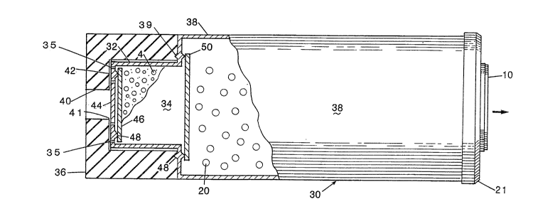
In this regard, attention is directed to Figures 2
and 3 and wherein a disposable GAC cartridge 30, similar
to that of Figure 1 but with some exceptions, is shown.
Dimensionally the cartridge 30 is constructed to fit
housings 6 of the type which receive cartridges 2 like
those shown in Figure 1. In lieu however of the internal
purification chamber 3, a reduced radius purification
chamber 32 projects from the inlet side of the GAC
chamber and wherein a resin bed 34 containing the resin
beads 4 is supported. A plurality of apertures 35 and
spacer ribs 37 to flow access to the bed 34.
A replaceable torroidal shaped filter 36 mounts
about the purification chamber 32 and spacer ribs 37. It
is formed of a relatively solid, porous material and
filters particulates less than 10 microns. sy making
the sediment filter 36 separately replaceable, the
overall life of the cartridge 30 is extended. The
throughput capabilities are also improved, since the
water flow over time does not experience par-tial filter
plugging, such as with the cartridge 2 and wherein the
foam sediment filter 14 typically becomes plugged. The
end of the filter 36 is compressively sealed to an
annular V-shaped ring 39 which protrudes from the forward
~all of the GAC chamber 38.
More of the details of the construction of the
purification chamber 32 and the mounting of the sediment
filter 36 thereto can be seen in Figure 3. It is to be
appreciated that the construction of the GAC chamber 38
is substantially the same as that shown in Figure 1,
although of a larger volume, and includes the GAC bed
~ :. , . . . . , , ~,
. ~ - . .
, ., , ' ' ,
..
.: . : . .: ~ .
,. .~ , .
22a~
material 20, post-filter assembly 22 (not shown) and
endcap 21.
The replaceable sediment filter 36 otherwise
exhibits an external diameter approximating that of the
GAC chamber 38. An internal, stepped bore 40 having a
ledge 42 mounts about the purification chamber 32 and
spacer ribs 37 and is sized to extend forward of the
purification chamber to create a space or gap 41. The aft
end abuts the seal 39 and GAC chamber 38.
The purification chamber 32 otherwise exhibits a
length of approximately 1 1/2 to 2 inches. The volume of
contained resin 4 (which is shown in partial cutaway) is
otherwise reduced and is approxima-tely thirty percent of
that used for the same overall sized cartridge of Figure
1. This reduced volume provides a cost saving and better
matches the useful life of the GAC particulate 20, which
has been increased in volume, to that of the iodine resin
4. Comparative tests have further corroborated that the
water purity and useful cartridge life for similarly
sized cartridges has improved with the reduction in resin
volume. In particular the cartridge 30 provides a purity
of 2.5 X 10⁹ ppm for the cartridge 2.
Separately bonded to the resin chamber 32 interiorly
of the inlet port 44 is a porous filter or screen disc 46
which is sonically bonded to the chamber end at an
annular projection 48. A downstream porous disk 50 is
similarly bonded to an annular projection 48 at the
interior forward face of the GAC chamber 38. In lieu of
a sonic bond, it is to be appreciated a variety of other
adhesives and plastic bonding techniques can be utilized
to bond the disks 48, 50 to the cartridge chambers 32,
38. The resin 4 is otherwise contained between the
impermeable outer chamber walls and the porous disks 48,
50 to the desired depth and reduced volume.
Appreciating that the resin chamber 32 might also
extend interiorly of the GAC chamber 38, attention is
directed to Figure 4 which discloses an assembly 59 that
:,
- ~ .
.
2 ~ ~
finds particular advantage, such as when traveling, for
individuals who desire a private filtration system. Such
a system is usable with conventional water supplies,
similar to those found in hotels, motels and the like.
Thus, the assembly 59 is readily mountable to a faucet
and not only filters macro sized contaminants from the
water, but also purifies the water of any viral or
bacterial contaminants.
The assembly 59 includes a cylindrical housing 60
containing inlet and outlet endcaps 62, 64 and relative
to which the inlet endcap 62 and purification chamber 74
are shown in partial cross section. A formed or bent
nozzle 66 extends from the outlet endcap 64. Secured to
the inlet endcap 62 is a length of tubing or hose 68
which is coupled to the inlet endcap 62 via a threaded,
draw-type connector assembly 70. The opposite tube end
is coupled to another connector assembly 70 and a
flexibly resilient faucet coupler 72. The faucet coupler
72 is formed of an elastomer material and provides an
inwardly tapered orifice (not shown) which fits over most
available faucets that might be encountered in a person's
travels. Although a friction fit coupler 72 is shown, it
is to be understood that a coupler assembly using a band
fastener or threaded faucet coupler could also be used to
advantage.
Upon fitting the coupler 72 over a faucet, the water
is directed to the iodine resin purification chamber 74
which extends interiorly from the inlet endcap 62 and
into the GAC chamber 76. A pair of porous disks 78
contain the iodine resin material 4 within the chamber
74. These disks 78 are sonically or adhesively bonded to
the chamber 74 to withstand the typical pressures
encountered relative to water entering a flared inlet
port 80.
A further example of an iodine resin purifier which
finds application with filtration housings 6 including a
replaceable GAC bed is shown in Figure 5. For the
: , . ,
~ .
,
'3
1 0
disclosed mounting, a replaceable GAC particulate 20 is
used in conjunction with an inlet/outlet manifold 8 that
screw couples to the GAC housing 6 in a reverse flow
fashion. That is, the normal inlet, when used with
replaceable cartridges 2, becomes the outlet or purposes
of the inventive arrangement of Figure 5. Thus, the
inlet channelway 82 channels water to a center port 84
and an elongated replaceable candle-like puriEication
chamber 86 which contains the iodine resin 4. The
purification chamber 86 is suspended from the manifold 8
at a slipfit connector 88 and is secured thereto via a
setscrew 90.
Shown in cutaway and contained within the chamber 86
between a pair of porous annular disks 92, 9~ is the
resin material 4. a bed length on the order of four
inches is provided. Otherwise, a separate pointed,
endcap 96 is secured via a second setscrew 98 to the
outflow end of the purification chamber 86. The endcap
96 exhibits a conically pointed profile and includes a
plurality of flow apertures 100. Other pointed profiles
may be used with equal efficacy.
The pointed pro-file particularly facilitates
mounting of the purification chamber 86 within the GAC
particulate 20. That is, when the GAC particulate 20 is
periodica~ly changed, it is necessary to unscrew or
remove the outer housing 6, dispose or clean the old
particulate and insert new particulate. The rejuvenated
particulate 20 and housing 6 is then brought to bear
against the purification chamber 86 and the purification
chamber is slowly inserted into the GAC particulate 20,
prior to the housing 6 being screwed onto the manlfold 8.
A porous end washer 102 otherwise separates the GAC
i material 20 from the outlet port 104 and the outlet
channelway 106 of the manifold 8. The annular V-shaped
ring 9 seals to the washer 102.
Still another construction of the invention is
disclosed in Figure 6 and wherein an assembly 110 is
.
: ; .
.
~ ~ .
:
~ ~r~
shown in partial cutaway which finds application for
military or recreational use. Specifically, a modular
canteen filtration system is disclosed which comprises a
squeeze bottle or bag 112, a purifica-tion/filtration
5 cartridge 114 and a conven-tional canteen 116.
For this assembly, a relatively sturdy, flexible bag
112 or polyethylene type bottle is used to collect water
which may be contaminated. This water can be collected
at the individual's convenience for subsequent or
immediate purification. A threaded nozzle portion of the
bottle mounts to a mating coupler 120 of the
purification/filtration cartridge 114. The cartridge
120, in turn, threadably couples at a collar seal 122 to
the spout 124 of a canteen or other personal water
storage device 116.
Referring to the cutaway portion of the purification
chamber 114, it is generally constructed in the shape of
a cylindrical housing 126 and provides for a suitable
porous pre-filter 128 which mounts adjacent the coupler
122 and typically comprises a relatively rigid disk-like
wafer. An appropriate volume of iodine containing resin
bed material 4 is next provided and contained between the
pre-filter 12~ alld a down stream porous divider filter
130. An appropria-te volume of GAC material 20 and a
suitable disk post filter 132 complete the i.nterior
construction of the cartridge 114.
Otherwise, a nozzle portion 134 provides a smooth
walled, blunt outlet port which is insertable into the
spout of the canteen 116. The surrounding, threaded
collar 122, which is secured in water tight relation to
the cartridge 114 via sealing arrangement (not shown), is
securable to the canteen 116.
Purification and filtration are achievable via a
gravity flow of the water through the cartridge, which
flow may be augmented via a vent hole (not shown) in the
canteen coupler 122. Otherwise, upon squeezing the water
bag 112, external pressure may be developed to facilitate
' ' '
12
flow through the cartridge 114. Where a bag type
collector chamber is used, the bag may be rolled as it is
evacuated and whereby a sustainable pressure may be
maintained relative to the cartridge. Depending upon a
desired useful cartridge life, the dimensions of the
cartridge 114 can be suitably tailored to accommodate
corresponding amounts of purification resin 4 and GAC bed
materia~ 2~.
While the present invention has been described with
respect to variously considered constructions, along with
various improvemerlts and modifications thereto, it is to
be appreciated that still other constructions may suggest
themselves to those of skill in the art. Accordingly, it
is contemplated the following claims should be
interpreted to include all those equivalent embodiments
within the spirit scope thereof.
What is claimed is: