Note: Descriptions are shown in the official language in which they were submitted.
2052207
- 1 -
INTRALUI'dINAL AN,~1STOI~IOTIC SURGICAL STAPLER WITH
DETACHED ANVIL
Field of~heInvention
This invention relates to surgical stapling. More
specifically, this invention relates to internal
anas~tomotic stapling. Most specifically, this invention
relates to internal anastomotic stapling of lumen,
particularly the intestines, wherein a circular ring of
stag>les is applied to the desired lumen.
B~k9round of the Invention
Generally, surgical stapling has made substantial advances
in the past decades. Specifically, in the area of
internal anastomotic stapling the advances have been quite
dramatic. Devices such as the Prozimate"" ILS stapler,
produced by the assignee of the present invention,
Ethicon, Inc., Somerville, New Jersey, have enabled
surgeons to perform operations and procedures which were
heretofore perceived as difficult, if not impossible, with
relative ease.
In performing surgical anastomotic stapling, generally the
two pieces of lumen are attached by a ring of staples.
During this procedure, a circular knife blade is used to
separate tissue which is held within the circular ring.
The circular ring is then removed with the stapler so that
a circular opening withing the lumen is completed along
thE: surgical stapling line.
SEN 64
205~2U7
- 2 -
In performing these surgical procedures however, it has
become desirable to separate the anvil head on which the
staples are clinched from the stapling portion from which
the staples are expelled. Advances along these lines have
been made in the past. It has been typical in the past
that the stapling side of the mechanism is attached the
head to the anvil portion through a "purse-stringed"
gathering of tissue.
In addition, it has been found that when the tissue
contained on the head portion of the stapler is attached
to tissue contained on the anvil portion of the stapler,
it is difficult to connect the anvil and head with proper
alignment of the staples into the anvils contained on the
anvil side.
Further, it has been found that it is difficult to perform
such stapling within a circular stapler such that the head
size is kept to a minimum on the outside with a maximum
inner cavity, so that more tissue can be gathered within
the anastomosed staple.
Also, although it may be desirable as part of this
invention to have the tissue which is gathered, pierced by
a relatively sharp trocar tip on the stapler head, it is
not always desirable for the stapler head to be
continually exposed with a sharp trocar tip. Rather, it
has been found that it is more desirable feature is to
have a sharp tip exposed only during a portion of the
attachment procedure.
SEN 64
_ 3 _ 2052207
Sumrnar,y of the Inven ion
Accordingly, it is an object of the invention to provide a
surgical stapler for anastomotic stapling in which there
is a separable anvil portion connectable to a stapling
portion and a trocar integral to the instrument on the
stapling portion of the instrument.
It is a further object of this invention to provide the
anvil portion with an extended tube in order to facilitate
purse stringing of tissue.
Moreover it is another object of the invention to provide
an alignment mechanism aligning the anvil portion and the
staples on the head or stapling portion of the shaft.
It is further an object of the invention to provide a
means of engaging the anvil portion of the shaft through
the tip of the integral trocar.
It is yet another object of the invention to provide a
means wherein the trocar tip is shielded ezcept for a
connection to the anvil portion of the shaft or during
purse-stringing.
These and other objects of the invention are described in
a surgical stapling device where staples are driven from
the head portion into the anvil portion of the device.
The anvil portion is detachable from the head portion, and
the head portion contains a trocar tip upon which is
attached the anvil. The anvil portion contains an
elongated sleeve which contains an opening through which
is placed the trocar tip. On the trocar tip there are
means which are engagable with a latching mechanism on the
anvil portion. There are contained alignment means which
SEN 64
- 4 -
2052207
align the anvil portion with staples on the head
portion of the instrument. There may also be
contained on the trocar tip a spring-loaded sleeve
which is retractable to expose the tip upon insertion
through purse-stringed tissue, or insertion of the
anvil shaft onto the trocar tip.
According to a further broad aspect of the present
invention, there is provided a surgical stapling
device which comprises a plurality of staples, the
staples initially contained in a head portion. The
surgical stapling device further comprises an anvil
portion 'into which the staples may be ejected from
the head portion. The anvil portion is detachable
from the head portion. The head portion contains a
shaft with a longitudinal axis and has an integral
trocar with a sharpened generally conical tip. The
sharpened tip has aligning means displayed radially
about the tip extending and parallel to the shaft
longitudinal axis for aligning the tip with the anvil
portion. The anvil portion further contains an anvil
head having a plurality of staple clinching anvils
and attached to an elongated sleeve with a hollow
interior and the anvil head further contains a
plurality of ribs placed radially within the sleeve
hollow exterior, the ribs aligning with the trocar
tip aligning means.
According to a still further broad aspect of the
present invention, there is provided a surgical
stapling device which comprises a plurality of
staples, the staples initially contained in a head
portion. The surgical stapling device further
comprises an anvil portion into which the staples may
be ej ected from the head portion. The anvil portion
is detachable from the head portion. The head
portion contains a shaft having a longitudinal axis
A
- 4a -
2U52~07
and an integral trocar having a sharpened generally
conical tip. The trocar tip contains a plurality of
grooves parallel with the shaft longitudinal axis.
According to a still further broad aspect of the
present invention, there is provided a surgical
stapling device which comprises a plurality of
staples, the staples initially contained in a head
portion. The surgical stapling device further
comprises an anvil portion into which the staples may
be ejected from the head portion. The anvil portion
is detachable from the head portion. The head
portion contains a shaft with a trocar having a
sharpened tip upon which may be attached the anvil
portion. The head portion further contains a first
elongated sleeve. The first elongated sleeve is
attached to the trocar by spring means. The trocar
tip may be exposed upon the exertion of force on the
sleeve and wherein the anvil portion is attachable to
the exposed trocar tip.
According to a still further broad aspect of the
present invention, there is provided a surgical
stapling device which comprises a plurality of
staples, the staples initially contained in a head
portion. The surgical stapling device further
comprises an anvil portion into which the staples may
be ejected from the head portion. The anvil portion
is detachable from the head portion. The head
portion further contains a shaft having a
longitudinal axis, and an integral trocar having a
sharpened tip, and further contains retracting means.
The trocar tip is retractable into a retracted
position on the shaft along the longitudinal axis by
operation of the retracting means. The anvil portion
contains a latching mechanism engageable with the
trocar tip and operable to keep the anvil releasably
- 4b -
2052201
engaged to the head portion. The anvil portion is
not releasable from the head portion when the anvil
portion is attached to the head portion with the
trocar tip in its retracted position.
The objects of this invention are more apparent when
taking into account the following drawings in
conjunction with the Detailed Description of the
Invention.
Description of the Drawings
Fig. 1 is a perspective view of a surgical stapler of
the present invention;
Fig. 2 is a perspective view of the head and anvil
portion of a surgical stapler of the present
invention;
Figs. 3, 4, 5 and 6 are side views of a closing and
stapling operation of the present invention;
Fig. 7 is an exploded perspective view of an anvil,
anvil shaft and trocar of the present invention;
Fig. 8 is a side view in partial cross-section of the
anvil taken along lines 8-8 of Fig. 2;
Fig. 9 is a side view in partial cross-section of a
closed anvil shaft seated upon a trocar tip as
described in the present invention;
Fig. 10 is a cross-sectional top view of an anvil
shaft taken along lines 10-10 of Fig. 9; and
~ l5.
205220
- 5 -
Fig. 11 is a partial cut away side view of a trocar
sheathing mechanism contained in the head portion of the
present invention.
Detailed Description of the Invention
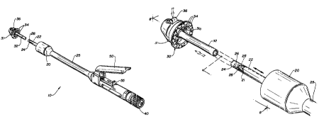
As seen in Fig. 1, there is disclosed a stapler 10
containing head 20, an anvil 30, an adjusting screw 40,
and trigger 50. The trigger 50 acts to operate the
stapler 10 when safety 55 is released. When trigger 50 is
activated, a firing mechanism not shown operates within
shaft 25 so that staples are ezpelled from the head 20. .
These staples are clinched about anvils 34 displayed
circumferentially about the head 31 of the anvil 30.
Simultaneously, a knife held within the head 20 acts to
cut tissue held within the circumference of the stapled
tissue between anvils 34. In this way, a circular lumen
may be pulled through the shaft and leave a closed tissue
about the stapler 10. The stapler 10 is then pulled
through the tissue leaving stapled tissue in its place.
As seen in Figs. 1, 2 and 7 there are various mechanisms
which form the invention in this circular anastomotic
stapler. More specifically, as seen in Figs. 1 and 2,
there is disclosed a trocar shaft 22 containing trocar tip
26. This trocar shaft 22 is contained integral to the
head portion 20 and is capable of piercing tissue. This
trocar shaft 22 is surrounded by sleeve 24 which
reciprocates into and out of the head 20. The sleeve 24
is held onto the head 20 by spring 23 which creates its
resiliency and allows reciprocation of sleeve 24 about
trocar shaft 22.
SAN 64
2052207
6
As seen in Figures 3 and 11, the trocar shaft 22 would
generally be covered by sleeve 24 so that purse-stringed
tissue may be placed over the sleeve 29. Nonetheless, the
tracar tip 26 is capable of puncturing through tissue when
pressure is applied. This is especialy useful when
connecting purse stringed tissue. In this way, the trocar
sleeve 24 with tip 26 exposed is capable of being forced
through a purse string so that the purse string is not
broken. After the trocar sleeve is forced through the
tissue, the sleeve 24 surrounds the trocar tip 26 so that
no further damage will be done and yet, the lumen is
adequately attached over the sleeve 24.
Corresponding to the tracar portion 24, there is the anvil
portion 30. On the anvil 30, there are contained anvils
34 displayed circumferentially around anvil head 31.
These anvils 34 correspond to staples held
circumferentially within head 20. As will be noticed in
Fig. 3, the anvil 30 may be placed within a lumen of
tissue, and then the tissue purse stringed about shaft
32.
Contained within anvil 30 there is an alignment mechanism
which is further disclosed in Fig. 8. As seen in Fig 8
w,..r.~~~ -r
there are serrations 29 contained within the
. These serrations correspond with
indentations or recesses 28 contained on the tip of the
trocar 26. When anvil 30 is placed over trocar shaft 22,
the serrations 29 find corresponding recesses 28 and
therefore are able to align anvils 34 with the staples
placed circumferentially about the head 20.
Furthermore, there is disclosed a unique method of
latching and unlatching the anvil to the head. More
specifically, as seen in Figures 2 and 7, release 36 is
S;EN 64
2C1~2~0~
_ 7 _
formed from a button-shaped lever which is contained by
release spring 36a on the head 31 of the anvil 30. This
release contains a wedge 35. as seen in Figure 10 which
forces open the central alignment locking clip 39b. This
locking clip is wedged between alignment clips 39a. Each
of these clips 39a, 39b has a centrally bored trocar hole
37b and holes 37a which fit on pin 37 in the head 31.
The trocar tip 26 of troca 22 i~~able to fit through the
w
centrally displayed holes ~ W n it is desired to lock
the anvil 30 upon the head 20, the generally springed
locking clip 39b is forced open and then closes shut .
around indentation or ridge 21 on trocar tip 22. This is
best seen~in Figures 8 and 10. When it is desired to open
the anvil 30 and separate it from the trocar shaft, force
is placed on release 36 such that wedge 35 pries open the
prongs of locking clip 39b. Hole 37b in clip 39b is now
the same size as holes 37b in each of the alignment clips
39a. In this way the shaft is slidable out of the anvil
shaft 32.
However, normally the spring which forms the locking clip
39b is biased in such a fashion that it is generally in a
smaller or "closed" position, such that it would fit
within indentation or ridge 21. Indentation 21 holds the
locking clip 39b, and the anvil 30 is adequately secured
on the trocar 22 contained within head 20.
In operation therefore as seen in Figures 3, 4, 5 and 6,
the anvil with two lumen attached to both the shaft 22 and
tubular anvil extension 32 respectively, is ready for
surgery. As seen in Figure 4, the anvil 30 is placed onto
shaft 22 such that trocar tip 26 is exposed and fits
within anvil extension 32. The sleeve 24 is pushed to an
exposed position so that it is telescoped within the head
6~EN 64
205220'
_ ~: ~ ~: ~,~ -
20. The holes.3~-a~ in alignment clips 39a and locking clip
39b guide the trocar through extension 32 into anvil head
31. When the trocar is adequately seated within anvil
head 31, locking clip 39b which contains the wedge shape
spring is caused to open and then grip about the
indentation 21. Because the recesses 28 have aligned
themselves with serrations 29 in the shaft 31, it is
ensured that the anvils 34 are aligned with the staples
contained in the head 20. As better seen in Figure 7,
serrations 29 have been aligned with anvils 34 during
manufacture through accurate placement of bosses 31a into
holes 32a when connecting anvil head 31 to extension 32.
The instrument now appears as two progimated pieces of
lumen as in Fig. 5. The adjusting screw 40 has pulled the
tissue closer to each other.
As seen in Fig. 6, the staples have been fired into the
anvils through the tissue. Once the staples are clinched,
a knife which cuts tissue held within the circumference of
the staples. Once this cutting is effected, the stapler
10 is pulled in the direction of the head 20 and through
the lumen so that a circumferentially closed lumen with a
inner tubular opening is now created.
After removing the stapler 10, the excess lumen held in
stapler 10 is disposed. The release 36 on anvil 30 is
pressed, as seen in Fig. 2 and 10. This causes the locked
mechanism as seen in Fig. 9 to open as alluded to in Fig.
7. The locking clip 39b now opens, allowing the user to
slide the anvil shaft 32 from the stapler head 20. In
this way the tissue that is held within the anvil 30 and
head 20 is removed.
SEN 64
20522U'~
_ g _
In this way there has been proper purse-stringing and
puncture by trocar 22, alignment between recesses 28 and
serrations 29, pull through of anvil head 31, locking clip
39b about the indention 21, and proper stapling and
cutting of the tissue. It is therefore to be realized
that the following claims and their equivalents are meant
to encompass the scope of the invention.
15
25
35
SFN 64