Note: Descriptions are shown in the official language in which they were submitted.
CA 020~2340 1999-03-10
DENTAL IMPLANT SYSTEM
BAC~GROUND OF THE INVENTION
This invention relates generally to improvements in
the formation and installation of dental implants, and more
particularly to dental implants having a metallic
bone-embedded fixture with which a post is interfaced to
support a prosthesis superstructure.
Surgical techniques for implantation of dental
pro~theses by means of a metallic bone-embedded fixture are
well known as disclosed for example in U.S. Patent Nos.
4,824,372, 4,872,839 and 4,934,935 to Jorneus et al.,
Brajnovic and ~dwards, respectively. According to the Jorneus
et al. and Brajnovic patents, a titanium bone-embedded fixture
is interfaced with a metallic abutment post, on which the
superstructure is supported, the post ha~ing an internally
shouldered access bore through which a screw fastener is
inserted to axially hold the implant components assembled.
Various problems and restrictions arise, howe~er, in the
attachment and retention of superstructures to such abutment
posts.
U.S. Patent No. 4,850,870 to Lazzara et al. is
directed to specific examples of attachment and retention of
superstructure on metallic abutment posts interfaced with
bone-embedded implant fixtures to which the posts are secured
by screw fasteners. The superstructure according to the
Lazzara et al. patent includes a separate coping portion
secured by means of another screw fastener to the core portion
of the abutment post.
CA 020~2340 1999-03-10
U.S. Patent No. 4,304,553 to Heinke et al. i6 also of
interest because it discloses a super structure support post
made of al~lmin~m oxide.
However, such po9t iS formed integral with the
bone-embedded fixture so as to introduce various problems
affecting installational flexibility and implant adjustment
or repair.
It is therefore an important object of the present
invention to provide an improved dental implant assembly and
an associated installational procedure to facilitate
customized formation and fitting of dental prostheses with
greater economy and flexibility.
A further object of the invention in accordance with
the foregoing object is to provide a dental implant assembly
that is less likely to be irreparably damaged and more readily
repaired.
Yet another object of the invention is to provide a
dental implant assembly having other desireable attributes not
heretofore available, such as increased strength and more
effective fluid sealing of the gum tissue region in which a
separate abutment post is interfaced with the bone-embedded
fixture to which it is attached by means of a screw fastener.
20~23~0
SUMMARY OF THE INVENTION
In accordance with the present invention, a ceramic
post is interfaced with the receiving end portion of a
metallic bone-embedded implant fixture to support a
dental prosthesis superstructure. The support post is
made of aluminium oxide so as to provide core strength
as well as flexibility in the selection of
superstructure arrangement and design to best meet
installational requirements and patient needs. Such
post mounts an anatomical shape trans-tissue formation
in abutment with the receiving end portion of the bone-
embedded fixture within an interface region between the
edentulous bone from which the fixture projects and the
gingival edge of the gum tissue. A curved transition
surface portion extends from the large diameter end of
the trans-tissue abutment formation to an elongated
cylindrical core portion of the post, cut to the desired
length to accommodate a custom designed superstructure.
Where the superstructure includes a separate coping
portion made of porcelain for example, the coping
portion is surface bonded without fastenings, by a
firing process, directly to the core portion of the
post. Such firing process forms a unity body in view of
the interacting properties of the ceramic material and
porcelain and without shrinkage as indicated for example
in U.S. Patent No. 4,585,417 to Sozio et al.
The abutment support post is formed with an aligned
access bore through which a screw fastener is inserted
and threaded into the bone-embedded implant fixture for
ycc/kb 3
20~23~0
attachment of the post thereto and to seal the interface
region by means of a deformable washer spacing the head
portion of the fastener from a shoulder on which it is
seated within the access bore in the post according to
certain embodiments of the invention. The washer
surrounds a connecting shank portion of the fastener of
minimum diameter and structural strength so that rupture
of the dental implant will most likely occur at that
location resulting in minimal damaqe to the dental
implant assembly facilitating retrieval of parts and
enabling easier repair.
BRIEF DESCRIPTION OF THE DRAWING FIGURES
The nature of the present invention will be more
readily understood by reference to the accompanying
drawing in which:
FIG. 1 i~ a section view of a dental implant
installation in accordance with one embodiment of the
invention;
FIG. 2 is a transverse section view of the implant
installation taken substantially through a plane
indicated by section line 2-2 in FIG. l;
FIG. 3 is a block diagram depicting the procedure
associated with formation and installation of dental
implant assemblies, such as that shown in FIGS. 1 and 2,
pursuant to the present invention;
FIGS. 4-8 are section views showing formation and
lnstallation of the dental implant of FIGS. 1 and 2 in
; different stages of assembly; and
ycc/kb 4
20~2~0
FIG. 9 is a section view of a dental implant
installation in accordance with another embodiment of
the invention.
FIG. 10 is a partial section view similar to that
of FIG. 8, illustrating yet another embodiment of the
invention.
: ycc/kb 4a
. . .
CA 020~2340 1999-03-10
DETAILED DESCRIPTION OF REFERRED EMBODIMENTS
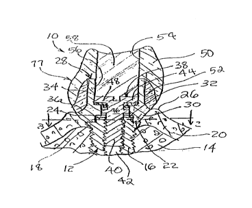
Referring now to the drawing in detail, FIGS. 1 and
2 illustrate a typical implant assembly in accordance with one
embodiment of the present inventlon, generally referred to by
reference numeral 10. A metallic implant fixture 12 generally
well known in the art and associated with the implant assembly
10 is embedded in edentulous bone 14 within a patient's mouth
in accordance with surgical implantation techniques developed
by Per-Ingvar Branemark et al., as referred to in the
aforementioned U.S. patents to Jorneus et al., Brajnovic and
Edwards. Such implant fixture is of titanium and includes an
externally threaded body 16 within the bone from which a
radially projecting flange portion 18 extends into the gum
tissue 20 forming an abutment shoulder 22 about a
cross-sectionally non-circular receiving end portion 24. The
receiving end portion 24 of the implant fixture is thus
exposed to an interfacing region between the edentulous bone
14 and the gingival edge 26 of the gum tissue as shown in FIG.
1.
With continued reference to FIGS. 1 and 2, an
abutment support post generally referred to by reference
numeral 28 is interfaced with the implant fixture 12 within
the aforementioned interfacing region by engagement with the
shoulder 22 at the small diameter end of a conical shaped
trans-tissue abutting section 30 of the post. A
cross-sectionally, non-circular socket opening 32 is formed
within the trans-tissue section of the post dimensioned to
match the receiving end portion 24 of the implant fixture with
a sliding fit so as to prevent angular displacement of the
CA 020~2340 1999-03-10
post relative to the implant fixture when interfaced in axial
alignment.
In accordance with the present invention, the support
post 28 is made of a ceramic material such as aluminum oxide
(Al2O3) so that it may be readily surface bonded, with or
without adhesives, to a variety of different superstructure
materials and arrangements on a supragingival section of the
post which includes an axially elongated cylindrical core
portion 34 as shown in FIG. 1. To enhance application and
retention of the superstructure on the supragingival section
of the post, an external shallow curved transition surface
portion 36 interconnects the conical trans-tissue section 30
with the cylindrical core portion 34 which has a uniform
diameter less than the maximum end diameter of the
trans-tissue section 30.
When properly interfaced with the bone-embedded
implant fixture, the support post is removably fastened to the
implant fixture by means of a screw fastener generally
referred to by reference numeral 38 in FIG. 1, to prevent
axial disassembly. Thus, the screw fastener includes an
externally threaded portion 40 treadedly inserted into an
internally threaded bore 42 formed in the bone-emhedded body
portion 16 of the implant fixture. The threaded screw portion
40 of the fastener is connected to a radially enlarged head
portion 44 by means of an intermediate shank portion 46 which
extends from the head portion through the interface region
into the receiving end portion 24 of the implant fixture. The
intermediate shank portion 46 is operative to locationally
limit implant rupture thereto and in cooperation with an
...... _. ~.. . . . . . ~.. ........ . . . . ..
, _ . ... .
CA 020~2340 1999-03-10
annular washer 48 is effective to seal the interface region,
as will be explained in detail hereinafter, in accordance with
the present invention.
In accordance with one embodiment of the invention as
illustrated in FIG. 1, the prosthesi~ superstructure supported
on the post 28 includes a restoration tooth 5C directly bonded
to a separate coping portion 52 made of porcelain material
which may be surface bonded, without any fasteners, to the
supragingival section of the post by a firin~ process to form
a unitary body therewith. The coping portion 52 thus
completely covers the supragingival core section of the post
28 as shown to firmly support the tooth 50 thereon. The tooth
is furthermore formed with an access opening 54 in axial
alignment with an axial bore 56 in the post 28 through which
the screw fastener 38 is inserted. The implant assembly 10
is accordingly finished by insertion of a suitable filler
resin 58 into the access opening and bore to cover the exposed
head portion 44 of the fastener 38 and complete formation of
the dental prosthesis.
The procedure involved in the customized formation of
a dental implant assembly such as that illustrated in FIGS.
1 and 2, is outlined in the diagram of FIG. 3. As diagrammed
in FIG. 3, a supply 60 of different standard sized
prefabricated support posts made of alllmin-lm oxide ceramic
material is available for selection of a post to meet
individual requirements of a post fitting operation 62 for
dental patients within which titanium fixtures 12 have been
implanted. The selected post is then cut to a desired axial
length as denoted by diagram block 64 for application of a
.. . . . . . . _ __ . ... . ,. . . _ . . _
. . .
CA 020~2340 1999-03-10
customized prosthesi9 superstructure to the post as denoted
by block 66 in FIG. 3. The prothesis supporting post is then
interfaced with the bone-embedded fixture and fastened thereto
while also sealing the interface region as depicted by diagram
block 68. The implant assembly is completed by a finishing
step as denoted by block 70.
FIGS. 4-8 illustrate the implant assembly of FIGS. 1
and 2 in different stages of assembly to further explain the
method outlined in FIG. 3 as well as to describe in detail the
interface region sealing and rupture control aspects of the
invention. The result of a post fitting step 62 is
illustrated in FIG. 4, showing a selected post 28 interfaced
with the bone-embedded fixture 12. The access bore 56 in the
post is shown in comml~nication with the socket 32 through a
smaller diameter bore 72 to form an annular shoulder 74 in
axially spaced relation to the socket 32. The fitted post is
then removed from the patient for application of the
prosthesis superstructure thereto as shown in FIGS. 5 and 6.
Initially the porcelain coping portion 52 of the
superstructure, as shown in FIG. 5, is applied to the post
according to one embodiment by a surface bonding firing
process as aforementioned. The support post may then be cut
to remove the portion of the cylindrical supragingival core
section projecting beyond the coping 52 and form a cut axial
end 76 as shown in FIG. 6. The prosthesis tooth 50 is then
applied as shown to form the superstructure 77 according to
the illustrated embodiment to complete the step 66 as
diagrammed in FIG. 3.
CA 020~2340 1999-03-10
The post fastening and interface sealing step 6
diay, -d ln FIG. 3 is performed as illustrated in FIGS. 7
and 8 showing insertion of the screw fastener 38. The
intermediate shank portion 46 of the fastener includes an
annular flange 78 having an outer diameter dimensioned for a
sliding fit within the small diameter bore 72. The flange 78
is axially spaced between the head portion 44 and the threaded
portion 40 of the fastener so as to axially define a shank
region 80 of ml~im~lm diameter and structurally weakest
cross-section to which implant rupture is thereby limited.
Further, the shank region B0 forms a seat for the washer 48
which is made of a deformable material such as silicone.
FIG. 7 shows the washer 48 in an undeformed condition
during installation of the fastener 38 as the flange 78
becomes aligned with shoulder 74 between bores 56 and 72 in
the post. Threaded insertion of the fastener is effected by
torsion applied to the head portion 44 by means of a tool 82,
for example, as shown in FIG. 7 resultiny in an axial
compressive force being exerted by the head portion on the
washer 48 for axial displacement thereof with the head portion
through bore 56. When the washer 48 engages the shoulder 74
as shown in FIG. 7, continued threaded insertion of the
fastener causes the head portion to compress the washer, as
shown in FIG. 8, as the flange 78 is axially displaced from
the shoulder 74. In its fully compressed and deformed
condition as shown in FIG. 8, the washer 48 will maintain the
head portion axially spaced from shoulder 74 and establish
fluid sealing contact with both the screw fastener made of
metal and the ceramic post. Such contact through the washer
... . . . ... . . . ... . . . . ..
.. ... .. . . .... .
CA 020~2340 1999-03-10
48 is far superior from a fluid sealing standpoint than the
imperfect sealing contact that would be otherwise established
between the head portion 44 and the post at shoulder 74.
Accordingly, effective fluid sealing of the interface region
from the access bore 56 in the post is realized when the
fastener 38 is fully inserted. The implant is finished by
filling of the access bore 56 with resin 58 as hereinbefore
described with respect to FIG. 1.
FIG. 9 illustrates another installational embodiment
of the present invention which is similar to that illustrated
in FIG. 1 in so far as the assembly 10' of FIG. 9 is
associated with a titanium implant fixture 12 threadedly
embedded in the endentulous bone 14 so that its receiving end
portion 24 is exposed to the interface region within the gum
tissue 20. The same type of screw fastener 38 may also be
threadedly inserted into the implant fixture 12 with a sealing
washer 48 carried on the intermediate shank portion 46 of the
screw fastener. However, an aluminum oxide support post 28'
that is of a tubular cylindrical shape throughout is utilized.
The trans-tissue end of post 28' has an annular shoulder
flange 74' thereon axially spaced from the head 44 of the
screw fastener by the deformed washer 48 to seal the interface
region otherwise in comm~lnication with the small diameter bore
72' within an anatomically contoured or sculptured porcelain
coping 52' surface bonded to the trans-tissue section of the
ceramic post 28'.
With continued reference to FIG. 9, it will be
observed that the end of the supragingival core section of the
post 28' is cut to a contoured open end shape 76' through
.... .
CA 020~2340 1999-03-10
which the fastener 38 is inserted before a supragingival
structure, including a restorative tooth 50', is fitted
thereon. An additional screw fastener 84 may be utilized to
secure such supragingival structure to the core portion of the
post 28' at an angle to its longitu~;nAl axis as shown. Also,
resin filler 58' may be utilized to cover screw head 44 and
fill the space within the bore of post 28' before the
restorative tooth 50' is applied and attached, after which the
assembly 10' is finished by filling the opening in the
supraglngival structure, exposing screw 84, with a resin
filler 86.
According to the embodiment illustrated in FIG. 10,
the screw fastener and washer described with respect to FIGS.
1-9 has been modified somewhat. A washer 48' as shown in FIG.
10 is retained on a minimum diameter portion 46' of the screw
fastener 38' axially spaced from both the head portion 44' and
the threaded portion 40' of the fastener. The head portion
44' accordingly abuts the shoulder 74 between the large and
smaller diameter bores 56 and 72 of the abutment post 28 when
the fastener 38' is fully inserted as shown in FIG. 10. The
washer 48' will then be disposed in a compressed condition on
the narrow diameter portion 46' of the fastener within bore
72 of the post 38' to effectively seal the gum tissue region
within which the post is interfaced with the implant fixture
12.
Further, it will be appreciated by persons skilled in
the art that various deviations from the described embodiments
of the invention are possible and that many modifications and
improvements may be made within the scope and spirit of the
11
CA 02052340 1999-03-10
invention. Thus, it will be understood that the invention is
not limited by the specific embodiments described, but only
by the scope and spirit of the appended claims.
... ~. . . . .