Note: Descriptions are shown in the official language in which they were submitted.
2~2f~
RBP File No. 680-060
Title: HEARING AID WAX GUARD
WITH INTEGRAI. BRIDGE:
FIELD OF THE INVENTION
.
This invention relates to a wax guard insert for
use with an in-the-ear hearing aid.
BACKGROUND OF THE INV~NTION
The advent of hearing aids which are inserted
directly into the user~s ear canal has highlighted the
problem of ear wax (cerumen) build up. Cerumen produced
in the ear canal can damage hearing aids in several ways.
Firstly, the wax can build up in the sound spout of the
hearing aid and reduce the sound output by a significant
amount. When cerumen totally blocks the sound spout the
sound output is nil and the hearing aid appears dead.
Secondly, cerumen may migrate through the sound
spout and into the hearing aid receiver thereby causing
irreparable damage to the transducer and necessitating
extensive repair work.
In addition, wax accumulation presents a problem
even if the sound spout is only partly blocked because
removing the wax from the hearing aid during cleaning may
result in wax inadvertently falling down the sound spout
into the receiver port.
As a result of the wax build-up and migration
problem, various attempts have been made to delay the
progress of the wax into the sound spout and receiver port
of the hearing aid. Such attempts are shown, for example,
in U.S. Patent No. 4,553,627 filed October 22, 1984,
European Patent Application No. 0287315 filed December 4,
1988, and U.K. Patent Application GB2155276A filed June
18, 1984. The above patents show various approaches which
have been taken to provide a wax guard for the sound spout
of a hearing aid. However these proposals have had only
limited success in delaying the progress of wax into the
sound spout and receiver port or the hearing aid. The
~2~
-- 2 --
ease of removal and cleaning of the guard is very
important given the advanced age of many hearing aid
users.
SUMMARY OF THE INVFNTION
It is therefore an object of this invention to
provide a wax guard system which deters the migration of
ear wax into the sound spout of an in-the-ear hearing aid.
In one aspect the present invention provides a
wax guard insert for use in a hearing aid shell, said wax
guard insert comprising:
(a) a body adapted to be secured to said shell,
said body having an outer surface adapted
to face outwardly of said shell and an
inner surface adapted to face inwardly in
said shell,
(b) said body having a passage extending
therethrough and through said outer and
inner surfaces, so that said outer urface
has an opening therein forming part of said
i 20 passage,
; (c) and bridge means formed integrally with
said housing and extending over said
opening, said bridge means shielding at
; least a part of said opening to deter ear
wax from entering said opening.
Further objects and advantages of the invention
will appear from the following description, taken together
with the accompanying drawings.
BRIEF DESCRIPTION OF DRAWINGS
In the accompanying drawings:
Fig. 1 is a partly sectional view of a portion
of a hearing aid having a wax guard system
according to the inventisn;
Fig. 2 is a rear view of a housing for the wax
3S guard system of Fig.1;
,. ;~
':
,
2Q~2,
-- 3 --
Fig. 3 is an elevation view of an insert for the
system of Fig. 1 ;
Fig. 4 is another elevation view of the insert
of Fig.3;
Fig. 5 is a plan view of the insert of Fig. 3;
Fig. 6 is a rear view of a modification of the
insert of Fig. 3; r
Figs. 7a and 7b show acoustic filters for use in
the insert of Fig. 3;
Fig. 8 is a side sectional view of a tool for
installing and removing the Fig. 3 insert;
Fig. 9 is an end view of the tool of Fig. 8; and
Fig. 10 is a partly sectional vlew of a modified
hearing aid having a wax guard system according
to the invention.
DEq~AIL~D DESCRIPq~ION OF PREFERR13:D EIIBODIMENT
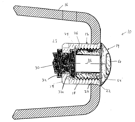
Reference is made first to Figs. 1 to 5, which
show a wax guard system 10 according to the invention.
The wax guard system 10 consists of a housing 12 and a wax
guard insert 14. The housing 12 is located in the canal
portion 16 of a hearing aid shell and the wax guard insert
14 fits into the housing 12.
The housing 12 has a generally cylindrical
barrel 18 which fits into a corresponding hole 20 in the
end of the canal portion 16. The housing 12 also has an
outer bevelled flange 22 which seats the housing snugly
flush with the outer surface of the canal portion 16 of
the shell. The housing 12 is held to the canal portion 16
b~ glue.
Inside the housing 12 is an internal passage 24
having an internal thread 26. The thread 26 extends from
the inner side of flange 22 to a position adjacent an
internal flange 28. The internal flange 28 constricts the
inner diameter of internal passage 24 at the inner end of
the passage. Notches 29 in the exterior of flange 28 aid
in removing the housing 12 from a mold.
.
', - ' ': .
~2~
-- 4 --
Inside the canal portion 16, and extending from
the housing 12 in a direction toward the interior of the
canal portion 16, is a soft tubing 30 having ribs 32 on
its outer surface. The ribbed tubbing 30 is attached at
its end remote from the housing 12 to a hearing aid
receiver (not shown).
To insert the ribbed tubing 30, the wax guard
insert 14 must be outside the housing 12. The ribbed
tubing 30 is squeezed so that it will fit past the opening
in internal flange 28, and then is fed ~or pulled) through
the housing 12 from the internal flange 28 past the outer
flange 22 until the receiver (not shown) is seated at its
proper location in the hearing aid. A rib 32a of the
tubing 30 now engages with the internal flange 28 of the
housing 12. The ribbed tubing will extend along past the
internal flange 28. Since the tubing 30 is resilient, it
is pulled out or stretched slightly past the outer flange
22; the excess is cut off at rib 32a, and the tubing then
snaps back so that rib 32a rests against internal flange
28. The wax guard insert 14 can then be inserted into the
housing 12.
The wax guard insert 14 (best shown in Figs. 3
to 5) comprises an insert body 38 having a cylindrical
portion 40 and an outer disk-shaped flange 42. The
cylindrical portion 40 has an outer thread 44 which mates
to the inner threads 26 of the housing 12. The insert
body 38 also has an internal passage 46 which extends
therethrough. The passage 46 terminates in an outwardly
facing opening 48 in the flange 42, and in an inwardly
facing opening at the inner end S0 of the body 38.
The outer surface 52 of the flange 42 carries a
bridge 54 which crosses over the opening 48. The bridge
54 is generally of "dog bone" shape as viewed in plan
(Fig. 5), having widened ends 56, and having a narrow
center 58 where the bridge crosses the opening 48. The
bridge 54 is also higher at its center 58 (as best shown
in Figs. 1 and 2) and lower at its ends 56.
', . .
2, ~
-- 5 --
At its center 58 the bridge 54 carries a thin
domed disk 60. The disk 60 is of slightly greater
diameter than that of the opening 48 in flange 42. The
inner surface 62 of disk 60 is generally flat, but the
outer surface 64 is domed outwardly as shown.
The purpose of the disk 60 is to shield the
opening 48 from wax. The disk 48 in effect "ploughs~ wax
aside as the hearing aid is inserted into an ear. The
disk 60 also helps to deter wax from entering the opening
48 after the hearing aid has been inserted into an ear.
While the disk 60 is preferably of slightly
larger diameter than the opening 48 it can be of the same
diameter, or slightly smaller if desired.
While the insert passage 46 has been shown as a
~; 15 "straight through" passage, it can alternatively if
desired have a partial obstruction formed at its inner
end, as shown in plan view in Fig.6. As there shown, a
plate 66 may be inserted within the passage 46 covering
opening 50, but with a cross-shaped opening 68 therein.
This additionally helps to deter the passage of wax into
the hearing aid.
Additionally or alternatively, an acoustic
filter can be inserted into the passage 46 to modify
~electively the frequency response characteris~ics of the
hearing aid. Fig. 7a shows an open cell foam filter 70
which can be press fitted into the passage 46. Fig. 7b
shows a filter 72 of sintered metal which can be placed in
; passage 46. Filters 70, 72 attenuate undesired high
frequencies and also obstruct the movement of wax through
the passage 46.
The entire wax guard system 10 (both the housing
12 and the insert 14) are moulded, typically of nylon or
other suitable material. However housing 12 can also be
machined.
35After the housing 12 has bee~ glued into the
hearing aid sound spout, the insert 14 is screwed therein
using a suitable tool to grip the disk 60 or bridge 54.
.. , .. : -
. ...,, ., . ~;
: ' : :
J ~4 5/~ s~
If and when the insert 14 becomes plugged with wax, it can
be removed (typically by a hearing aid service person) for
cleaning or it can be thrown away and a new insert screwed
into position since the inserts are extremely small and
inexpensive.
Figs. 8 and 9 show a tool 80 for removing and
replacing insert 14. Tool 80 has a handle 82 with four
prongs 84 protecting therefrom. The inner surfaces of
prongs 84 are concave, as shown at 86, to define an inner
circle 88 of diameter slightly less than that of disc 60.
Tool 80 is of resilient plastic, so when the prongs 84 are
forced over disc 60, the prongs 84 flex or distort
slightly outwardly, gripping the disc 60 in a friction
fit. Tool 80 can then be turned to screw the insert 14 in
or out. The prongs 84 will normally penetrate any wax
present on disc 60 or wide grip despite such wax.
Fig. 1 has shown a custom hearing aid shell,
i.e. one in which the shell including the sound spout 16
is shaped to fit an individual user~s ear canal. If
desired, an inner standard or ~'stock~' shell 90 tFig. 10)
can be used which is always of the same shape, so as to
fit the hearing aid components in a standard way, with an
outer shell 92 whose outer surface is used as a base on
which to add material such that the resultant form fits
the contours of the user~s ear. The system shown in Fig.
10 is essentially the same as that shown and described
previously and primed reference numerals indicate parts
corresponding to those of previous figures. In Fig. 10,
the housing 12' has been slightly modified to eliminate
the bevelled flange 28 and instead to provide a reduced
diameter portion 94 in the outside surface of the housing
12' at its outer end. The reduced diameter portion 94
accommodates a correspondingly sized hole 96 in the shell
90 and extends through a slightly smaller hole 98 in shell
92. Housing 12~ may be secured to shell 90 by glue. Outer
shell 92 is secured to inner shell 90 by screwing insert
14 into the housing 12~.
:'
2~2~?,J.~
As before, passage 46' can be filled with an
acoustic filter of desired acoustic resistance, to
selectively modify the frequency response characteristics
of the hearing aid. A typical filter is indicated at 70 in
Fig. 10.
:.
.