Note: Descriptions are shown in the official language in which they were submitted.
2052~72
The present invention relates to a rotary-anode
type x-ray tube and, more particularly, to an improve-
ment in the structure of a bearing for supporting a
rotary-anode type X-ray tube.
As is known, in a rotary-anode type X-ray tube, a
disk-like anode target is supported by a rotary struc-
ture and a stationary shaft having a bearing portion
therebetween, and an electron beam emitted from a
cathode is radiated on the anode target while the anode
target is rotated at a high speed by a rotating magnetic
field generated by energizing the electromagnetic coil
of a stator arranged outside a vacuum envelope, thus
irradiating X-rays. The bearing portion is constituted
by a rolling bearing, such as a ball bearing, or a
dynamic pressure type sliding bearing which has bearing
surfaces with spiral grooves and uses a metal lubricant
consisting of, e.g., gallium (Ga) or a gallium-indium-
tin (Ga-In-Sn) alloy. Rotary-anode type X-ray tubes
using the latter bearing are disclosed in, e.g.,
Published Examined Japanese Patent Application
No. 60-21463 and Published Unexamined Japanese Patent
Application Nos. 60-97536, 60-117531, and 62-287555.
In the rotary-anode type X-ray tubes disclosed in
the above-mentioned official gazettes, molybdenum (Mo)
or an Mo alloy, or tungsten (w) or a W alloy is used as
a material for a rotary structure and a stationary shaft
constituting a sliding bearing. However, a bearing
:
~2~7~
surface consisting of such a metal is easily oxidized in
the air in an assembly process, and the resulting oxide
film causes a deterioration in wettability between the
bearing surface and a liquid metal lubricant consisting
of a Ga alloy. For this reason, a special process is
required to remove the oxide film formed on the bearing
surface to make the assembly process cumbersome.
Moreover, a reliable dynamic pressure type sliding bear-
ing function may not be obtained.
It is an ob;ect of the present invention to provide
a rotary-anode type X-ray tube which ensures excellent
wettability between a bearing surface and a liquid metal
lubricant, and can maintain a stable operation of a
dynamic pressure type sliding bearing.
According to the present invention, there is pro-
vided a rotary-anode type X-ray tube comprising:
an anode target;
a rotary structure which has a rotation center axis
and to which said anode target is fixed;
a stationary structure, coaxially arranged with
said rotary structure, for rotatably holding said rotary
structure;
a hydrodynamic bearing formed between said rotary
structure and said stationary structure, having a gap
in which a metal lubricant is applied, the lubricant
being in liquid state during rotation of said rotary
structure, said hydrodynamic bearing including a surface
~2472
layer contacted with the lubricant layer, reacted with
at least one element of gallium (Ga), indium lIn) bis-
muth (Bi) or tin (sn) and having a thickness of not less
than 1 ~m.
According to the present invention, since a thin
surface layer containing a refractory metal for a
bearing surface base member, such as Mo or W, and
gallium, or a thin surface layer containing a nitride,
a carbide, or a carbonitride ceramic material for a
bearing surface base member and gallium is formed on
the surface portion of each sliding bearing surface,
excellent wettability between the bearing surfaces and
a liquid metal lubricant is ensured, thus maintaining
a stable operation of a dynamic pressure type sliding
bearing. In addition, assembly of this bearing is
facilitated, and a highly reliable bearing operation can
be performed.
This invention can be more fully understood from
the following detailed description when taken in con-
junction with the accompanying drawings, in which:
Fig. 1 is a longitudinal sectional view showing a
rotary-anode X-ray tube according to an embodiment of
the present invention;
Fig. 2 is an enlarged sectional view showing a part
of the X-ray tube in Fig. l;
~ig. 3 is an enlarged sectional view showing a part
of the X-ray tube in Fig. l;
20~2~2
Fig. 4 is a longitudinal sectional view showing the
structure of the bearing shown in Fig. l;
Figs. 5 and 6 are cross-sectional views respec-
tively taken along lines 5 - 5 and 6 - 6 in Fig. 4;
Fig. 7 is a graph showing the content ratios of
metal components of the bearing shown in Fig. l;
Fig. 8 is a partially enlarged longitudinal
sectional view showing a rotary-anode type X-ray tube
according to another embodiment of the present
invention; and
Fig. 9 is a partially enlarged longitudinal
sectional view showing a rotary-anode type X-ray tube
according to still another embodiment of the present
invention.
The preferred embodiments of the rotary-anode type
X-ray tube of the present invention will be described
below with reference to the accompanying drawings. Note
that the same parts are denoted by the same reference
numerals throughout the drawings.
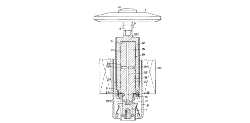
As shown in Figs. 1 to 6, a disk-like anode target
11 consisting of a heavy metal is integrally fixed to a
rotating shaft portion 13 extending from one end of a
cylindrical rotary structure 12 with a screw 14. A sta-
tionary shaft 15 is fitted in the cylindrical rotary
structure 12. A disk-like flange 16 is fixed to the
one opening portion of the rotary structure 12. An
anode support portion 17 at the one end of the
2~2~72
stationary shaft 15 is vaccum-tightly fitted in a glass
vacuum envelope 18. A hydro-dynamic pressure sliding
bearing portion 19 similar to the one disclosed in each
official gazette mentioned above, is formed at the fit-
ting portion between the cylindrical rotary structure 12and the stationary shaft 15. That is, spiral grooves 20
and 21 similar to those described in each official
gazette mentioned above are formed in the outer surface
and two end faces, of the stationary shaft 15, which
serve as its sliding bearing surface. The sliding bear-
ing surface of the rotary structure 12, which opposes
the sliding bearing surface of the stationary shaft 15
is formed into a smooth surface or a surface in which
spiral grooves or the like are formed as needed so that
thrust and radial bearings are constituted. Note that a
ferromagnetic cylinder 12a consisting of an iron mate-
rial is fitted on an Mo member as the base member of the
rotary structure 12, and a cylinder 12b consisting of
a material having a low electrical resistance, e.g.,
copper, is fixed on the cylinder 12a.
Mo or an Mo alloy (to be simply referred to as Mo
hereinafter) is used as a base member for the rotary
structure 12 and the stationary shaft 15. Thin reaction
layers containing Mo as a base member metal for a bear-
ing surface and at least Ga (to be simply referred asMo-Ga reaction layers) 31 and 32 are respectively formed
on the bearing surfaces. These Mo-Ga reaction layers 31
2 0 ~ 2 ~ / ~
-- 6
and 32 are formed on the surfaces of the base members
in advance to have thicknesses of 1 ~m to 100 ~m.
~xamples of formation of such layers will be described
later.
Note that the rotary structure 12 and the station-
ary shaft 15 are assembled to have a gap ~ of about
20 ~m between their bearing surfaces on which the Mo-Ga
reaction layers 31 and 32 are formed. A lubricant stor-
age chamber 22 is formed in the stationary shaft 15 by
forming a through hole in its central portion in the
axial direction. The lubricant storage chamber 22 also
serves as a circulation path for a lubricant. One end
22a of the lubricant storage chamber 22 is opened in an
end face, of the outer surface of the stationary shaft
15, which has the spiral grooves 20. Thus, the lubri-
cant storage chamber 22 is communicated with a gap of
the thrust bearing. In addition, an intermediate por-
tion of the outer surface of the stationary shaft 15 is
slightly tapered to form a small-diameter portion 23,
and three radial paths 24 extending from the lubricant
storage chamber 22 are formed at angular intervals of
120~ to be symmetrical about the axis. The lubricant
paths 24 are communicated with a low-pressure space
between the cylindrical rotary structure 12 and the
small-diameter portion 23. The lubricant in the
low-pressure space is maintained at a pressure lower
than that of the gaps of the thrust and radial bearings.
2 ~ 7 2
The other end 22b of the central lubricant storage
chamber 22 is sealed by a plug 25 consisting of the
same Mo material as that for the stationary shaft 15.
A circumferential cavity 26 between a small diameter
5 portion of the stationary shaft 15 and the rotary struc-
ture 12 is formed near the plug 25. Three radial paths
27 extending from the central lubricant storage chamber
22 to the circumferential cavity 26 are formed at angu-
lar intervals of 120~ to be symmetrical about the axis.
Thus, the lubricant storage chamber 22 iS communicated
with the circumferential cavity 26 through the radial
paths 27 and the cavity 26 is also communicated with the
gap of the thrust bearing between of the stationary
shaft 15 the stepped face and the stepped inner face of
15 the rotary structure 12. A gap ~, and the spiral
grooves 20 arld 21 of the bearings, the paths 24 and
the lubricant storage chamber 22 communicating therewith
are filled with a liquld metal lubricant (not shown)~ as
described above. Owing to the presence of the lubricant
20 storage chamber 22, a sufficient amount of liquid metal
lubricant for a long-term operation is supplied into the
gaps of the bearings, when an amount of the lubricant is
decreased in the gaps of the bearings, thus maintaining
a required operation of the hydro-dynamic pressure type
25 sliding bearing.
The end portion of the stationary shaft 15 iS inte-
grally brazed to the anode support portion 17 consisting
2~2~72
of an iron material. A stator 40 having an electromag-
netic coil is arranged outside the vacuum envelope as to
oppose the rotary structure 12. A rotating magnetic
field is generated by the stator 40 to rotate the rotary
anode at a high speed in a direction indicated by P in
Fig. 1. An electron beam emitted from a cathode (not
shown) are impinged on the anode target 11 to irradiate
X-rays. Most of the heat generated in the target 11 is
dissipated by radiation, while part of the heat is
transferred from the rotary structure 12 to the liquid
metal lubricant and is dissipated through the stationary
shaft 15. Since the Mo-Ga reaction layers 31 and 32
constituting the bearing surfaces have sufficiently high
electrical and thermal conductivities as the rotary-
anode type X-ray tube, they properly function as paths
for anode currents and heat. In addition, the layers 31
and 32 exhibit sufficiently high mechanical strength,
thus providing a rotary-anode type X-ray tube having
stable bearing operation performance.
Examples of formation of the Mo-Ga reaction layers
31 and 32 on the bearing surfaces of the rotary struc-
ture 12 and the stationary shaft 15 will be described
below.
In one of the examples, spiral grooves 20 and 21
having herringbone patterns are formed in predetermined
portions, of the base members of the rotary structure 12
and the stationary shaft 15 consisting of Mo, which
~0~2~72
serve as bearing surfaces. These Mo base members are
then heated to 700~C in a vacuum to clean the bearing
surfaces. In the same vacuum, the temperature of the
base members is kept within the range of about 450 to
550~C, e.g., at 500~C, and the base members are dipped
into a bath of Ga (including an alloy consisting of Ga
as a main element, e.g., a Ga-In-Sn alloy). The base
members are kept in the bath for a predetermined period
of time and are cooled down. With this process, Mo-Ga
reaction layers 31 and 32, each consisting of a compound
containing Mo, Ga, In, and Sn, are formed on the sur-
faces of the base members, thus obtaining bearing
surfaces. Each of the layers 31 and 32 is diffused into
the original surface of a corresponding base member to a
depth of about 2.5 ~m and is deposited on the surface to
a thickness of about 4.5 ~m and hence has a total thick-
ness of about 7 ~m.
Note that Fig. 7 shows the distribution of the
contents of the metal components at the respective
positions, in the direction of depth, of the surface
portion of the bearing member manufactured in this
manner. This graph shows the molar ratios approximately
calculated from the contents obtained by EPMA analysis.
The position of an alternate long and short dashed line
A in Fig. 7 corresponds to the original surface of each
Mo base member. A region constituted by a metallic com-
pound mainly consisting of Ga and Mo as the base member
2~52~7~
-- 10 --
material, which ranges from the position A to a dotted
line B can be recognized. The thickness of the region
from the position A to the position B is about 2.5 ~m.
The ratio of Ga to Mo is abruptly reversed near the
position B, and a metal region consisting of only Mo
extends inward from the position B. That is, Ga in the
bath is diffused in the Mo base member to form the Ga-Mo
reaction layer from the original surface to the position
B. In the region from the original Mo base member sur-
face A to a surface C, a metallic compound layerconsisting of Ga, In, Sn, and Mo can be recognized.
Note that the surface C is a flat surface obtained by
removing a rough surface portion resulting from the
above-mentioned reaction process from the uppermost sur-
face by a thickness of about 2 ~m by polishing. It isconfirmed that the reaction layer on this surface por-
tion has sufficiently high hardness as a slidlng bearing
surface. In this manner, the Mo-Ga reaction layer 31
(or 32) is formed from the surface C to the predeter-
mined depth position B. Note that the gap between thebearing surfaces of the rotary structure and the sta-
tionary shaft before the formation of reaction layers is
set to be larger than a predetermined gap by the thick-
ness of these reaction layers so that the predetermined
gap can be formed between the bearing surfaces upon for-
mation of the reaction layers. The low-melting metal,
in the bath, which is used to form a reaction layer
2~2~ 72
together with the base member metal may consists of only
Ga or an alloy of Ga and another metal having a rela-
tively low melting point.
Since the maximum temperature of the X-ray tube
during an operation is about 400~C, and this state lasts
only for a short period of time, the reaction layer of
each bearing surface hardly changes, and the bearing
surface having high hardness is maintained. In
addition, even if an oxide film is formed on this reac-
tion layer during the assembly process, this oxide film
can be very easily removed. Furthermore, if a liquid
lubricant consisting of Ga or a Ga alloy is filled
between the bearing surfaces upon assembly of the bear-
ing surfaces as a sliding bearing, stable direct contact
can be ensured, with excellent wettability, between the
bearing surfaces consisting of the Mo-Ga reaction layers
and the liquid metal lubrlcant. Therefore, assembly is
facilitated, and a satisfactory function as a dynamic
pressure type sliding bearing can be obtained.
In the embodiment shown in Fig. 8, an Mo~Ga reac-
tion layer 31 or 32 having a relatively large thickness
of about 50 ~m is formed in the surface of the base mem-
ber of a rotary structure or a stationary shaft by a
method similar to that described above. The surface of
this reaction layer is ground to have a predetermined
diameter as a bearing surface, and at the same time,
spiral grooves 20 or 21 are formed in the reaction layer
~52~72
by a mechanical process or chemical etching. According
to this manufacturing method, an X-ray tube including a
dynamic pressure system sliding bearing having desired
high-precision spiral grooves and a desired gap between
the bearing surfaces can be manufactured.
Note that after the Mo-Ga reaction layer is formed,
at least a region from a surface portion C to a original
base member surface A may be removed by polishing to
expose a compound layer (corresponding to the region
from the position A to the position B in Fig. 7) in
which Ga is diffused in Mo, and spiral grooves may be
formed in the exposed compound layer as a bearing
surface. With this process, an X-ray tube can be
manufactured, which exhibits higher hardness at a
high temperature, and has stable bearing surfaces having
excellent wettability with a liquid metal lubricant.
In the above-described embodiments, surface reac-
tion layers are independently formed on the rotary
structure and the stationary shaft in the form of parts.
However, the present invention is not limited to this
but an X-ray tube can be manufactured in the following
manner. The rotary structure and stationary shaft are
manufactured and assembled in advance in such a manner
that the gap between bearing surfaces is larger than
that of the finished product. The gap between the bear-
ing surfaces and a lubricant storage chamber are filled
with a lubricant consisting of Ga or a Ga alloy.
2~5~2~7~ -
- 13 -
Thereafter, these components are heated at about 500~C
in a vacuum for a predetermined period of time and are
subsequently cooled down. With this process, Mo-Ga
reaction layers, each having a predetermined thickness,
are respectively formed on the bearing surfaces of the
rotary structure and the stationary shaft, and the
remaining Ga or Ga alloy lubricant is left in the gap
between the bearing surfaces, which is reduced to a pre-
determined gap. The gap between the bearing surfaces
and the lubricant storage chamber are replenished with
a Ga or Ga alloy lubricant, as needed, thus completing
an X-ray tube. According to such a manufacturing
method, if the amounts of Mo-Ga reaction layers to be
formed are accurately managed by controlling the heat-
treatment temperature and the time for the heat treat-
ment in consideration of the gap between bearlng
surfaces of a finished product, the assembled structure
of the rotary structure and the stationary shaft can
be finished as a product without disassembling the
structure, thus requiring no additional assembly steps.
Therefore, such a manufacturing method is suitable for
mass production.
Note that the base member of each bearing surface
may be constituted by W (including an alloy mainly con-
sisting of W), niobium (Nb) (including an alloy mainlyconsisting of Nb), or tantalum (Ta) (including an alloy
mainly consisting of Ta). Alternatively, another metal
2~247~
- 14 -
such as iron or stainless steel, or a ceramic material
may be used as a bearing constituent element, and a
bearing surface base member may be formed by coating a
thin layer consisting of a refractory metal, such as the
one described above, on a portion, of the bearing con-
stituent element, which serves as a bearing surface. If
these refractory metals are used as bearing surface base
members, the thicknesses of reaction layers consisting
of these base member metals and Ga and formed on the
surface portion thereof must be set to be 1 ~m or more
in order to facilitate control of the formation of the
reaction layers.
The base member of a bearing surface may be consti-
tuted by a ceramic material such as titanium nitride,
zirconium nitride, or a ceramic material such as
vanadium carbide, titanium carbide, or niobium carbide.
Alternatively, the base member may be constituted by a
carbonitride ceramlc material such as vanadium
carbonitride or tltanium carbonitride.
In addition, a bearing surface base member may be
formed by coating a layer consisting of a nitride, a
carbide, or a carbonitride ceramic material on a surface
portion of another metal. If a bearing surface base
member consisting of a nitride, a carbide, or a
carbonitride ceramic material is to be formed, the
thickness of a reaction layer consisting of the bearing
surface base member and Ga or Bi is preferably set to be
20~2472
- 15 -
1 ~m or more in order to facilitate control of formation
of the reaction layers. More specifically, as shown in
Fig. 9, the CVD method is employed to deposit a titanium
nitride ceramic layer 33 having a thickness of several
~m on a bearing surface portion, of a stationary shaft
15, in which spiral grooves 20 and 21 are formed in
advance. In addition, a reaction layer 34 consisting of
titanium nitride and Ga or Bi may be formed on the
resultant surface to a thickness of about 2 ~m, thereby
forming a bearing surface.
Note that since the reaction layer consisting of
the bearing surface base member and Ga or Bi has elec-
trical conductivity, the layer can also be used as part
of a path of an anode current for the X-ray tube.
The present invention is not limited to a lubricant
mainly consisting of Ga, e.g., a Ga, Ga-In, or Ga-In-Sn
lubricant. For example, a lubricant consisting of an
alloy containing a relatively large amount of bismuth
(Bi), e.g., a Bi-In-Pb-Sn alloy, or a lubricant
consisting of an alloy containing a relatively large
amount of In, e.g., an In-Bi or In-Bi-Sn alloy, may be
used. Since these materials have melting points higher
than the room temperature, it is preferable that a metal
lubricant consisting of such a material be preheated to
a temperature higher than its melting point before an
anode target is rotated.
As has been described above, according to the
,
~2472
present invention, since a thin reaction layer contain-
ing a bearing surface base member and at least Ga is
formed on a surface portion of a sliding bearing
surface, excellent wettability between this bearing sur-
face and a liquid metal lubricant can be ensured,thereby maintaining a stable operation of a dynamic
pressure type sliding bearing. In addition, there is
provided a rotary-anode type X-ray tube which allows
easy assembly of a bearing and has a highly reliable
bearing function.