Note: Descriptions are shown in the official language in which they were submitted.
~2~6~
SPILL CONTAINMENT DEVICES
The present invention relates to spill containment
devices employed in minimizing pollution in the delivery of fuels
and other liquids to an underground storage tank.
In recent years there has been an increasing appreci-
ation of the harmful environmental affects resulting from spillingof fuel into the soil. One source of such soil contamination is
found in the transfer of fuel from delivery trucks to underground
storage tanks, as are employed in gasoline service stations. In
transferring fuel, a connection must be made between a relatively
large hose and a riser pipe which projects upwardly from the
storage tank. Normally, the riser pipe connection is disposed
below ground level and accessed by removing a lid from a manhole
opening wherein the riser pipe terminates.
Despite taking precautions thereagainst, there is,
almost always, some spillage of fuel either when the hose is
connected to or disconnected from the riser pipe. Further,
accidents can and do occur which result in substantial quantities
of fuel spilling during the transfer process. In the past the
spilled ~uel has simply been allowed to pass into the subsoil,
resulting in contamination which has several adverse affects. Now
that the hazards of soil contamination have been recognized, many
jurisdictions now have regulations which require that such spills
be contained.
The need for eliminating this saurce of soil contam-
ination is recognized by several proposals in the patent litera-
ture, several of which, known as spill containment devices, have
found commercial acceptance. U.S. patents Nos. 4,659,251 -
S~ S '~
Petter, et al., 4,696,330 Raudman, et al., 4,763,806 -
Podgers et al. are e~emplary. These clevices, generally, comprise
a rim structure which is mounted in a concrete apron and de~ines
the upper end of a an upwardly open spillage container, sometimes
referenced as a bucket or sump. A riser pipe, extending from an
underlying stora~e tank, projects through the bottom of the bucket
and terminates below the level of the rim, within the interior of
the bucket. A sealed connection is provided between the bottom of
the bucket and the riser pipe so that any ~uel spilled, when the
storage tank is filled with fuel, will be contained within the
bucket and not flow into the subsoil. While proposals vary,
provision i5 usually made to selectively discharge fuel, spilled
into the bucket, into the riser pipe and thus into the storage
tank.
One of the problems encountered in providing such
spill containment devices is that there is a likelihood, if not a
certainty, that, after installation, there will be relative move-
ment between the rim structure, which is usually anchored in a
concrete apron at ground level, and the riser pipe which is
connected to the storage tank several feet below ground. This
relative movement, usually associated with frost heaving, has the
potential of causing loss of the sealed connection between the
riser pipe and the bottom of the bucket.
This problem has been recognized and several proposals
made to prevent loss o~ the sealed connection between the bottom
of the bucket and the riser pipe when there is relative movement
therebetween, in either a vertical or lateral direction. Several
of these proposals are based on the uses of bellows, which, in one
~2~
fashion of another are interposed between the riser pipe and the
rim structure which is anchored in the concrete apron. Generally
speaking the use of bellows has been found to be an effective
means for accommodating this relative movement.
One shortcoming founcl in prior art containment devices
is that they are difficult to maintain. This is to say that leaks
can develop over a period of time. For example, the referenced
bellows are formed of an elastomeric material which, over a
prolonged period~ can deteriorate to the extent that leaks are
created as the bellows are flexed. Also, through abuse, such
bellows can be punctured or otherwise develop a leak, to the end
that spilled fuel is no longer contained in the bucket. Thus
these bellows, or their equivalents, or other components employad
in obtaining the desired seal, require both inspection and
replacement as a normal maintenance function of the spill con-
tainment device.
Accordingly, one object of the present invention is to
improve the maintenance capabilities of spill containment devices.
Another function provided by a bellows, or other
flexible, sealed connection between a riser pipe and the bottom of
a containment device bucket is to facilitate construction of a
storage tank loading area at a service station. Installation of a
storage tank, riser pipe and an overlying concrete apron is far
from a precision procedure. The general procedure, in an original
installation, is to first place a storage tank in an excavation
with the riser pipe mounted thereon. The depth of the excavation,
and the length of the riser pipe are predetermined to bring the
top of the riser pipe to a given relationship with the surface of
~ ~ c7j i'~
the concrete apron, which is to be poured after the containment
device is mounted on the riser pipe, and the excavation back
filled. Seldom is the containment device at the desired height.
This is particularly true where several storage tanks and con-
tainment devices are to be associated with a common concrete apronand the containment devices are, desirably, to be at the same
height. The situation is further aggravated in that a riser pipe
will not necessarily be plumb, requiring the containment device to
be angled relative to the riser pipe to bring the rim structure
thereof to a desired horizontal position.
While prior containment devices, employing such bel-
lows, or other flexible connections, have the capability of being
adjusted to properly align the rim structure thereof, the process
if tedious and time consuming.
Accordingly, a further object of the present invention
is to facilitate the installation of spill containment devices.
Further objects of the invention are found in provid-
ing an improved connection with the metal rim which supports a lid
for the spillage container; mlnimizing, if not eliminating, flow
of ground water into the spillage container; and improving the
connection between the spill container rim and the concrete apron
on which it is mounted.
In accordance with one aspect of the invention, the
foregoing ends are broadly attained by a containment device com-
prising a bucket member in the form of a vertically disposed shelland a riser pipe extension adapted to be mounted on a storage tank
riser pipe and comprising riser pipe means. A bottom member is
secured in fixed, assembled relation to the bucket and has an
2~0
opening through which the riser pipe extension projects in spaced
relation thereto.
The riser pipe extension has an upper end portion
above the bottom member and a lower end portion disposed beneath
S the bottom member. ~n upper flexible member, preferably in the
form of a bellows, extends between the bottom member and the upper
portion of riser pi.pe extension to provide for relative movement
between the bucket member and the riser pipe means. The bucket
member, bottom member and upper flexible member define an upwardly
open, spillage container.
A lower, flexible member extends between the bottom
member and the lower portion of the riser pipe extension and de-
fines, at least in part, a lower chamber beneath the spillage con-
tainer.
Preferably, means are provided for draining fuel from
the spillage container to the lower chamber and then into the
lower portion of the riser pipe extension through openings formed
therein. The draining means, preferably, include a passageway
extending through the bottom member and a selectively actuable
valve for controlling fuel flow through this passageway.
In a preferred form, the bottom member is a generally
planar annulus and the opening for the riser pipe extension is
defined by an upstanding annular flange~ The lower end of upper
bellows is clamped to the upstanding flange and its upper end is
clamped to the upper portion of the riser pipe extension. The
bottom member also has a depending annular flange and the bellows
has an upper end sealingly clamped to the depending flange and a
lower end clamped to the lower portion of the riser pipe exten-
~ J~
sion. The diameter of the depending, bottom member flange issubstantially greater than opening defining flange, with the drain
opening is disposed between the Elanges~
The connections of the bellows to the riser pipe
extension and the connection of the bottom member to the bucket
member are releasable to permit removal of these items for repair
and/or replacement.
The preferred connection between the bucket member and
bottom member comprises vertical slots in the bucket member and
lugs projecting from ~he bottom member and seating on the bottoms
of the slots. A circumferential groove is formed in the bucket
member, above the bottoms of the slots and receives a manually
removable snap ring which overlies the bottom member lugs.
In another embodiment of the invention, a single
elastomeric separating member comprises portions which function as
the upper bellows, bottom member and lower bellows.
In accordance with another aspect of the invention,
the above stated ends are attained by a device comprising a bucket
member in the form of a vertically disposed shell and a bottom
member having a fixed assembled relation. The bottom member has
an opening through which the riser pipe means projects. A flexi-
ble member, preferably in the form of a bellows, is secured to the
bottom member and has an opening, which defines means adapted to
be sealingl~ secured to riser pipe means to define a spillage
container, in combination with the bucket and bottom members, and
to provide for relative movement between the bucket member and the
riser pipe means.
~ ~3 ~
The bottom member is capable of being telescoped
through the upper end of the bucket member to and from its
assembled relation. Releasable means lock the bottom member in
its assembled relation. Releasable means are provided for
clamping the opening defining means of the flexible member to the
riser pipe means, whereby the bottom member and bellows may be
separately removed from the bottom member for repair or
replacement.
In accordance with another aspect of the invention,
the foregoing ends may be attained by a containment device
comprising bucket means comprising a vertically disposed shell;
bottom forming means defining an upwardly open, spillage container
in combination with the bucke-t means; means attaching the bottom
forming means to the riser pipe means of a storage tank and means
permitting relative movement between the upper end of the bucket
means and the attaching means.
Adjustable means are provided for establishing the
relative relationship between the upper end of the bucket and the
attaching means. Additionally, the means for establishing the
relationship between the upper end of the bucket means and the
attaching means are disengageable. This structure enables the
bottom forming member to be attached to the riser pipe means; the
top of the bucket means to be brought to a desired position; the
top of the bucket secured in place in the installation process,
and then the adjusting means disengaged to pexmit relative
movement to occur as may be occasioned by natural forces.
In accordance with another aspect of the invention,
the above stated objects of the invention are attained by a
~ J ~
containment device comprising means fo:rming an upwardly open,
spillage container, the upper end of which is a shell with a
generally circular outline. An annular rim telescoped over and
mounted on this shell.
Mounting of the rim is accomplished through the
provision of L-shaped grooves on the shell which are open at the
upper end thereof. The rim has inwardly projecting lugs which are
receivable in the L-shaped slots, permitting the rim to be
telescoped over and then rotated with respect to the shell to
bring the lugs into the horizontal portions of the L-shaped slots,
thereby locking the rim thereon. Clips may then be provided in
the vertical portions of the L-shaped grooves to prevent rotation
which would permit inadvertent alignment of the lugs with the
vertical por~ions of the L~shaped grooves.
The rim supports a lid which closes the opening into
the spillage container. In order to minimize, if not fully
prevent ground water from entering the spillage container, the
upper surface of the rim is spaced beneath the upper end of the
circular shell and is angled downwardly towards its outer periph-
ery. An annular rib projects upwardly from the upper surface of
the rim. The lid has a peripheral lip which engages the upper
surface of the rim outwardly of the rib and supports the lid
thereon.
The circular shell may have an outwardly projecting
~houlder providîng support for the rim and aligning it at right
angles to the shell. Additionally, a sealing ring may be disposed
between this shoulder and the rim. Also, the shell may further
comprise a lower cylindrical section defining the outer bounds of
the shoulder. The rim then comprises a depending flange tele-
scoped over the lower cylindrical section to be aligned thereby.
As previously indicated, the containment device rim is
embedded in a concrete apron. In order to more securely lock the
rim into this apron, a plurality of anchors may be mounted on the
rim. Each anchor is formed of metal wire and comprises a pair of
downwardly angled legs connected by a central coil. Preferably
the rim has lugs disposed beneath its upper surface and the
anchors are, respectively, mounted on the lugs, with the coil of
each anchor being expanded to yielding grip the lug on which it is
mounted.
A further problem arises in the installation of
containment devices of the type which provide a bellows connection
to accommodate relative movement between a bucket member and riser
- 15 pipe means. Such containment devices are mounted on the riser
pipe means which are accessible prior to backfilling the excava-
tion for the storage tank. Where the bucket member is open at its
lower end, backfill material can work its way upwardly and thus
has the potential for damaging the bellows.
In the past, various makeshift means ha~e been em-
ployed, with limited success, to provide a barrier for preventing
backfill material from entering the bottom of the bucket member.
Accordingly, yet another object of the present
invention is provide protection for such bellows connections.
This end may be attained by a method for installing
containment device on a riser pipe means projecting upwardly from
an underground storage tank, where the containment device com-
prises a bucket member which is open at its lower end and bellows
means are disposed in the lower end of the bucket member to
accommodate relative movement between the bucket member and the
riser means. The method includes the step of backEilling an
excavation in which the containment device is disposed and is
characterized by the step of securing an open ended bag, at one
end, to the lower end of the bucket member and securing the bag,
at the other end thereof, to the riser pipe means. The securing
step is performed prior to backfilling to thereby protect the
bellows means from backfill material.
This end may also be attained by a containment device
of thé type just described, which is characterized by a circumfer-
ential groove formed in the bucket member, adjacent the lower end
thereof. The groove facilitates attachment of the one end of the
open ended bag thereto.
The above and other related objects and features of
the invention will be apparent from a reading of the following
description of embodiments thereof, with reference to the accom-
panying drawings, and the novelty thereof pointed out in the
appended claims.
In the dra _n~s:
~igs. 1 and 2 illustrate the manner in which the
present spill containment device is installed;
Fig. 3 is an elevation, in section and on an enlarged
scale, of the spill containment device seen in Figs. 1 and 2;
Fig. 4 is a plan view of the spill containment
device, as shown in Fig. 3, with various portions broken away and
in section;
Fig. 5 is a fragmentary, vertical section, on an en-
larged scale, of the upper end portion of the spill containment
device, taken on line 5 5 in Fig. 4;
Fig. 6 is an elevation of the upper end portion seen
in Fig. 5;
Fig. 7 is a section, on an enlarged scale, taken on
line 7-7 in Fig. 4;
Fig. 8 is section, on an enlarged scale, taken on
line 8-8 in Fig. 3;
Fig. 9 is a view, on an enlarged scale, taken on line
9-9 in Fig. 3;
Fig. 10 is a view taken on line 10-10 in Fig. 9;
Fig. 11 is a view, on an enlarged scale, of upper and
lower portions of a riser pipe extension seen in Fig. 3;
Fig. 12 is a view, on an enlarged scale and with por-
tions broken away and in section, of a portion of a bucket member
seen in Fig. 4;
Fig. 13 is a section taken on line 13-13 in Fig. 12;
Fig. 14 is an elevation similar to Fig. 3, illus-
~rating the exterior surfaces of certain components, and withadjusting components removedi
Fig. 15 is an elevation, in section, of an alternate
embodiment of the invention, which has an increased capacity;
~ Fig. 16 is an elevation~ in section, of an alternate,
"below grade" embodiment of the invention,
Fig. 17 is an elevation, in section, of an alternate
embodiment of the invention employed in retrofitting existing fuel
tanks with a spill containment device;
11
jC~
Fig. 18 is an elevation, in section, of a further
alternate embodiment of the invention;
Fig. 19 is a view of a portion oE Fig. 1~, on an
enlarged scale, and
Fig. 20 is a section taken on line 20-20 in Fig. 18.
As indicated above, spill containment devices are
employed to capture fuel which may be spilled in the process of
being transferred from a delivery truck to an underground storage
tank. Figs. 1 and 2 illustrate the initial installation of the
present spill containment device, which is generally indicated by
reference character 20.
Fig. 1 shows the upper portion of a tank T which has
been placed in an excavation, with soil backfilled to the upper
portion thereof. A riser pipe P is mounted on the tank T and
projects thereabove. The containment device 20 is then mounted on
the upper end of the riser plpe P by means described below.
After the containment device 20 is mounted on the
riser pipe P, the excavation may be further backfilled and a layer
L, of gravel, provided to a level appro~imately six to eight
inches below a rim 22, at the upper end of the containment device
20. Next a layer of concrete, commonly referenced as an apron
and identified be reference character A is poured over the
backfilled layer L. It is a preferred practice to bring the upper
surface of the apron A to a level at or slightly above the lower
surface of the rim 220 Concrete is then troweled around the rim
to form a conical drain surface S which diverts surface water away
form the opening into the containment device 20.
12
Reference is next made to Yigs. 3 and 4 for a
description of the containment device 20.
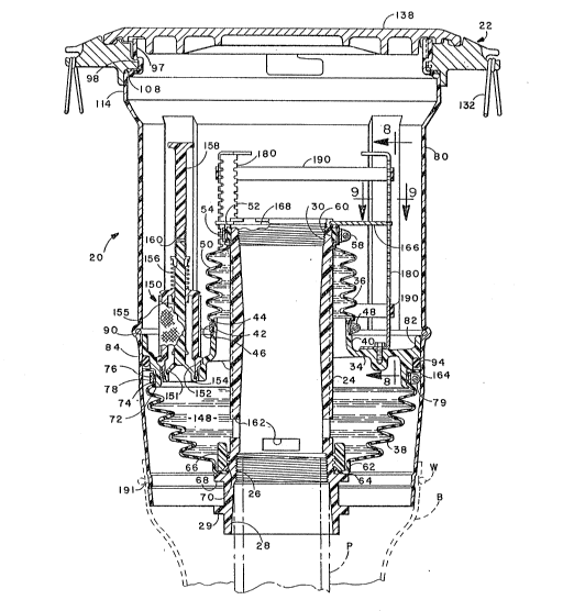
The device 20 comprises a central, riser pipe
extension 24, the lower end of which is threaded onto the riser
pipe P, when the device is installed. It is to be noted that the
pipe threaded portion 26, which provides for mountlng the riser
pipe extension 24, is spaced inwardly from its lower end, and that
a guide bore 28, tapered at a low angle, is provided to bring the
riser pipe extension 24 into alignment with the riser pipe P
during mounting of the containment device 20 thereon. The guide
bore 2~ facilitates proper engagement of the threaded portion 26
with the threads on riser pipe P.
It will be seen that a hex shaped flange 29 is
provided adjacent the lower end of the riser pipe extension 24.
The hex flange 29 (See also Fig. l) is adapted to be received by
a wrench and provide means for torquing the riser pipe extension
24 into secure engagement with the rise:r pipe P.
A female pipe threaded portion 30 is provided at the
upper end of the riser pipe extension 24 and is adapted to receive
an adapter, or other means, ~not shown in Fig. 3) which will
.enable a fuel delivery hose to be attached thereto.
The riser pipe extension 24 is preferably formed of a
synthetio resinous material to minimize the weight of the con-
tainment device. It is aIso preferable that a this resinous
material, commonly referred to as a "plastic", be electrically
conductive so that the containment device may be grounded at its
connection with the delivery hose. Nylon is a suitable material
for this and other structural components herein.
2~)~2~
While resinous materials have the necessary strength
fo.r the purposes served by the riser pipe extension 24, extreme
pressures can be encountered in threading the metal riser pipe P
into the threaded portion 26, or a metal adaptor into the threaded
portion 30. Of particular concern is damage to the threads by
cross threading, where proper alignment is not obtained between
the threaded components. To minimize damage to these resinous
material threads, the initial portions thereof are formed by metal
coils 32 (Fig~ 11).
The riser pipe extension 24 is flexibly and
resiliently mounted on a base member 34 (also referenced as a
bottom member herein) by an upper bellows 36 and a lower bellows
38 and comprises, in combination therewith, a sub-assembly which
facilitates initial testing of the bellows seals, as is later
detailed. The base member 34 has an annular flange 40 projecting
upwardly therefrom and defining a central opening 4~ which is
nominally coaxial of and spaced from the riser pipe extension 24.
The bellows 36 is provided with an annular mounting sleeve 44, at
its lower end which is telescoped over the upper end of the flange
40. A band clamp 46, having worm type adjusting means 48, is
tightened against the bellows sleeve 44 to secure the bellows 36
to the flange 40 and provide a liquid seal between the bellows 36
and the base member 34.
The upper fold 50 of the bellows 36 projects inwardly
towards the riser pipe extension 24 and has an annular mounting
sleeve 52 formed thereon (See also Fig. 11). A band clamp 54,
having a worm type adjusting means 58, clamps the sleeve 52
against an annular seal 60 which is telescoped over the upper end
14
C~ r ~ ~ ~
of the riser pipe extension 24. The upper end of -the bellows 36
is thus clamped, in sealing engagement with the upper end of the
riser pipe extension 24.
The lower end of the lower bellows 38 is secured to
the riser pipe extension 24. The lower fold of the bellows 38
extends inwardly and has a cylindrical portion 62 (See also Fig.
11) terminating in an inwardly projecting flange 64. A large ring
nut 66 is threaded onto the riser pipe extension 24 and clamps the
bellows flange 64 against an underlying flange 68, which projects
outwardly from the riser pipe extension 24. The ring nut 66 also
clamps an O-ring seal 70 into sealing engagement with the riser
pipe extension 24 and the bellows flange 64. The lower end of the
lower bellows 38 is thus releasably secured to the riser pipe
extension 24 in sealing engagement therewith.
The lower bellows 38 flares upwardly and outwardly to
the base member 34. The base member 34 has a depending flange 72
which provides a cylindrical surface 74 (See also Fig. 13) over
which a cylindrical sleeve 76, at the upper end of the lower
bellows 38, is telescoped. A band clamp 78~ provided with a worm
type adjusting means 79, secures the cylindrical sleeve 76 to the
flange 72. The upper end of the lower bellows 38 is thus secured
to the base member 34 in sealing engagement therewith.
The base member 34 is removably mounted on a cylindri-
cal, open ended, bucket member 80. To this end, the base member
34 has an upstanding rim 82 at its outer periphery, the outer
surface of which is telescopingly received in a cylindrical,
central portion 84 of the bucket 80. A plurality of upwardl~
open, vertical grooves 86 are formed in the bucket 80 (Figs. 4,
CI`fJ ~ ~ ~
12 and 13). The base member rim 82 has a plurality of outward]y
projecting lugs 88 which are received in the grooves 86 and are
supported by the bottom ends thereof. A retaining ring 90
overlies the lugs 88 and is received in a circumferential groove
92 formed in the bucket 80. The base member 34 is thus mechani-
cally locked in assembled relation with respect to the bucket
member 80.
A liquid seal is provided between the base member 34
and the bucket 80 by a sealing ring 94 which is compressed between
an annular seat 96 formed on the base member and the inner surface
of the cylindrical bucket section 84. The inner surface of the
bucket 80, immediately above the section ~4, is flared outwardly
to assist in compressing the sealing ring 94 when the base member
is displaced downwardly to its illustrated, assembled position.
Where resinous materials are employed to fabricate the
bucket 80, there is the possibility that the resinous material
will "relax" and expand in diameter so that an effective seal will
not be obtained between the sealing ring 94 and the cylindrical
section 84. Should this occur, provision is made for the applica-
tion of a hoop rin~ R to reduce the diamet~r of this section. To
this end, the lower end portion of the bucket 80 is tapered
inwardly to facilitate telescoping of the hoop ring R thereover.
The rim 22 is mounted on the bucket 80 by a bayonet
arrangement now to be described. The upper end of the bucket 80
comprises a generally cylindrical shell section 97 having inwardly
projecting, upwardly open, L-shaped slots 98 at its upper end ~see
Figs. 3, 4, 5 and 7). The rim has inwardly projecting lugs 100
which are disposed in the lateral legs of the slots 98. A retain-
16
2 ~3 ~
ing clip 102 is secured in the vertical leg of at least one o~ theslots 98 to prevent rotation of the rim 22 relative to the bucket
80 and inadvertent separation of the rim from the bucket.
Each clip 102 comprises an upper U section wh.ich is
tensioned to grip the wall of the bucket. A tab 104 projects
outwardly to positively prevent movement of the adjacent lug 100
into alignment with the vertical leg of the slot 94. Preferably
the bucket 80 is formed of resinous "plastic" material and the
clips 102 are formed of spring steel. The U-section of the clip
10 102 is provided with a tongue 106 which d.igs into the bucket so as
to prevent inadvertent removal of the clip.
In addition to the mechanical connecti.on between the
rim 22 and bucket 80, thus provided, it is also preferred to
provide a liquid seal therebetween. This end is attained by a
15 sealing ring 108. The sealing ring 108 is compressed between an
annular seat 110 formed on the undersurface of the rim 22 and a
shoulder 112, which extends outwardly from the lower end of the
upper cylindrical section 97 to an enlarged cylindrical section
114 of the bucket 80. The rim 22 has a depending annular flange
20 116 which is telescoped over the cylindrical section 114 to
prevent tilting or the rim relative to the bucket 80. That is, it
is desired to maintai~ the rim 22 and bucket 80 in coaxial
relationship, with the annular portions of the ring at right
angles to this common axis.
The upper portion of the rim 22 is defined by an out-
wardly projecting flange 1180 the upper surface of which is
angled downwardly away from the central opening defined by the
rim. The lower surface of the flange 118 has downwardly pro-
~ 3~
jecting strengthening lugs 120 and bosses 122 which terminate in a
common plane which defines the level to which the concrete apron A
will be poured. A plurality of the lugs 120 are formed as anchor
arms 124, disposed beneath notches 126, which facilitate casting
S of the rim.
An anchor 128 is mounted on each of the anchor arms
124 to be embedded in the concrete apron A and anchor the rim 22,
and, thereby, the containment device 20, relative thereto. The
anchors 128 are formed of spring steel, or like material, and
comprise a central coil 130 with outwardly angled legs 132, which
terminate in horizontal ends 134. The anchor arms 124 have
enlarged outer;ends 136 which maintain the anchors thereon during
installation of the containment device. The anchor legs 132 are
drawn toward each other to enlarge the diameter of the coil 130 so
that it will pass over the enlarged end 136 to enable an anchor
128 to be mounted on an arm 124. Upon release of the legs 132,
the coil 130 grips the arm 124.
After installation, the upper end of the containment
device 20 is normally closed by a lid 138 which is supported by
the rim 22. More specifically the lid 138 has a peripheral lip
140 which seats on the upper surface of the rim flange 118 and
serves to prevent ground water from entering the bucket 80.
Pre~erably, further dam means are provided to give greater
assurance against ground water entering the bucket 80 and becoming
a source of contamination of the fuel. These means comprise an
annular rib 142 formed on the upper surface of the rim flange 118
and spaced inwardly of its central opening. Further dam means are
provided by the upper portion of the upper shell portion ~7 which
18
L''~
projects above the flange 11~. The undersurface of the lid 138 is
relieved to clear the rib 142 and the upper end of the bucket 80
so that the lid lip 140 supports the lid and provides a sealing
function.
Triangular, angularly spaced lugs 144 are provided on
the rim flange 118, outwardly of the lid 13~ and angled to the
height of the upper, outer periphery of the lid. These lugs
prevent inadvertent displacement of the lid, as by the blade of a
snow plow, while permitting water to drain away from the opening
to the containment device.
When installed in the fashion indicated in Figs. 2
and 14, the containment device 20 is mounted on the fuel tank
riser pipe P and a standard adapter AD has been attached to the
upper end of the riser pipe extension 24. The lid 138 is removed
and an appropriate connection is made between a fuel delivery hose
and the adapter AD. After delivery is completed, the hose is
detached from its connection with the riser pipe 24. Any fuel
which spills from the delivery hose during this process is
captured in the upper portion of the containment device which
functions as a spillage container 146, defined by the bucket 80,
the base member 34 and bellows 36.
Spilled fuel in the spillage container 146 is then in-
spected to make certain that it is not contaminated, water
contamination being of particular concern, requiring the contam-
inated fuel to be removed from the spillage container for disposalat some remote location. If the spilled fuel is not contaminated,
it is discharged into the fuel tank by way of a discharge chamber
148 defined by the base member 34 and the lower bellows 38.
19
A drain valve 150 provided at. a low point in the base
member 34. The drain valve controls drainage of fuel through a
passage 151 through the bottom member 34 and is positioned in this
passage by screws 153 and clamps 155 (Fig.4).
The drain valve 150 is of conventional design and
comprises a body member 152 and a poppet 154 (Fig.3). The poppet
154 is at the lower end of a stem 155 and is maintained in sealing
engagement with the body member 152 by a spring 156. The upper
end of the poppet stem 154 is connected to an upper rod 158 by a
10 flexible, spring connection 160. The upper rod 158 enables the
poppet stem to be depressed and fuel thus drained into the dis-
charge chamber 148. The flexible connection (spring 160) between
rod 158 and valve stem 155 prevents damage to the poppet stem, ~r
poppet, by accidental contact therewith as a hose connection is
made with the riser pipe extension 24.
When the poppet stem is depressed to open the valve
150, fuel flows from the discharge chamber 148 through openings
162 in the riser pipe extension 24 and then drains through the
riser pipe extension 24 into the riser pipe P and the tank T.
The described containment device provides significant
benefits in facilitating its assembly and installation on the
riser pipe of a storage tank, as well as its repair.
In the initial assembly of the containment device 20,
the components including the riser pipe extension 24, base member
25 34 and the upper and lower bellows 36, 38 may be assembled as a
sub-assembly. The lower bellows 38 may first be secured to the
riser pipe extension 24 by ring nut 66 and sealed thereto by O-
ring 70. The lower bellows 38 may then be secured to the base
2 ~
member 34 by the band clamp 78. The upper bellows 36 may then be
secured to the base member ~lange 40 by the band clamp 46 and to
the riser pipe extension 24 by the band clamp 54 and seal 60.
It will be noted that the upper sleeve portion 76 of
the lower bellows 38 (Fig. 13) is provided with a radial flange
164 which positions the sealing ring 94 relative to its seat 96.
The sealing ring 94 is, pre~erably, a component of the referenced,
initial sub-assembly.
The major components of this sub-assembly. i.e., the
riser pipe extension 24, the base member 34, the bellows 36, 38
and the principal components of valve 150 are, preferably, formed
of "plastic" materials so that it is lightweight and readily mani-
pulated during assembly. Nylon is an exemplary material suitable
for these components. This is to say that the only metal compo-
nents of this sub-assembly would be the band clamps 78, 46 and 54,
the thread inserts 32 and, optionally, the ring nut 66, all of
which have a relatively small mass.
The drain valve 150 (also a lightweight component) may
also be installed as a part of this sub-assembly~ or, optionally,
a plug may be threaded into the opening for the drain valve. In
either event, one end of the riser extension 24 may be plugged and
pressurized air introduced through the opposite end to pressure
the interior o~ the sub-assembly. This pressurization will reveal
whether sealed connections have been properly obtained between the
bellows 36, 38 and ~he riser pipe extension 24 and the base member
34. Leakage can be readily detected by immersing the pressurized
sub-assembly in water.
The described sub-assembly is next assembled with the
bucket member 80 simply by aligning the lugs 88 with the slots 86
and lowering the sub-assembly until the lugs 88 engage the bottoms
of the slots 86, which serve as positioning shoulders or abut-
ments. It is to be noted that the inner diameter of bucketpermits the sealing ring 94 to freely pass thereover until the
tapered section above the ylindrical portion 84 is reached. The
decreasing diameter of this tapered section then compresses the
sealing ring to provide an effective liquid seal between the
bucket 80 and the base member 34.
After the sub-assembly is thus positioned, it is
locked in place by the retaining ring 90, to provide an second
sub-assembly, which is also relatively light, since the bucket is
"plastic" and the retaining ring is of a low mass. This facil-
itates pressuxized testing of the seal between the bucket 80 andthe base member 34.
The rim 22 and lid 138 are the only metal components
of the containment device which have significant mass. The rim
22, which may weigh in the order of 30 pounds, may be assembled on
the second sub-assembly, which includes bucket 80, simply by
aligning the lugs 100 with the vertical portions of the slots 94,
lowering the rim and then rotating it to bring the lugs 100 into
the horizontal portions of the slots 94. Assembly may then be
completed by attaching the clips 102 in the slots 94. The lid 138
may also be set on the rim 22 and shipped as a component of the
containment device.
2~
The containment device 20 is installed on a riser pipe
P, in the fashion above referenced by threading the riser pipe
extension 24 onto the upper end of riser pipe P.
In laying out a storage tank installation, there will
be a grade level, reference plane established for the upper sur-
face of the apron A (Fig. 1). It is a common practice to install
multiple tanks so that a plurality of containment devices which
must be aligned (with respect to the lower surface of their rims
22) relative to the grade level. Installing tanks and riser pipes
so that containment devices can be thus positioned relative to a
reference plane with any degree of reliability, is a practical
impossibility.
The present containment device overcomes this problem
through the provision of means for adjusting the bucket 80
relative to the riser pipe extension 24. These means comprise a
support plate 166 (Figs. 3, 4, 8 and 9) which is mounted on the
upper end of the riser pipe extension 24. To this end, a circum-
ferential groove 168 is formed in the outer surface of the riser
pipe extension 24, with vertical openings 170 therefor. The plate
166 has a central opening 174 with inwardly extending projections
176 ~Fig. 9) which are alignable with the openings 170. The
plate 166 is telescoped over the riser pipe extension 24 to bring
the projections 176 into alignment with the groove 168 and then
rotated to bring the projections into the groove 168. It is to be
noted that the upper bellows flange 52 is provided with an
inwardly extending sleeve extension 178 (Fig. 11). The bellows
36 being formed of a resilient material, the extension 178
provides a restraining ~orce which prevents rotation oE the plate
166 and its inadvertent separation from the riser pipe extension
24.
The adjustment means further comprise three vertical,
support arms 180. The support arms have horizontal tabs 182 which
are clamped to the base member 34 by screws 184. Each support arm
180 has a series oE notches 186 along its opposite side edges.
The notches 186 are disposed in a series of sets of notches with
each set of notches lying generally in a plane normal to the axis
of the bucket member 80. The plate 166 has notches 188 which
respectively receive the support arms 180 with the marginal
portions thereof engaging the arm notches 186. Rubber bands 190
embrace the support arms 180 to yieldingly maintain the arms in
engagement with the plate notches 188.
When the containment device is initially assembled,
the support arms 180 maintain the bucket 80 (and rim 22) in a
nominal vertical relationship with respect to the riser pipe
extension 24 and also maintain the plan~e of the rim 22 at right
angles to the vertical axis of the riser pipe extension.
After the containment device 20 has been mounted on a
riser pipe P, the orientation of the rim 22 relative to the
desired grade level, reference plane is checked. If the rim is
too high or too low, the support arms 180 are released from the
plate notches 188 and then reengaged therewith after the rim has
been positioned at the desired height. If the riser pipe P has
angled from a vertical position, the rim 22 will be correspond-
ingly angled from a horizontal plane, which is its usual, desired
orientation. In such a situation, one or more of the plate
notches 188 can be shifted for engagement with a different set of
24
2 ~
arm notches 186 to thereby tilt the hucket 80 relative to the
riser pipe extension 24 and thereby bring the rim 22 ta the
desired angular relation relative to the grade level, reference
plane.
After the desired relationship of the rim 22 has been
established, as just described, the excavation is backfilled and
the apron A poured and to complete the installation of the
containment device. The rim 22 is anchored in the concrete apron
and the relationship of the device with the riser pipe P and the
tank T is thus established.
In backfilling the excavation there is the possibility
that gravel, or the like~ might be introduced into the lower end
of the bucket 80 and damage the lower bellows 38 or the seal
between the sealing ring 94 and the bucket. This is particularly
so where the back fill is introduced in the form of a water
slurry.
To eliminate this potential problem, after the con-
tainment device 20 is mounted on the riser pipe P, an open ended
bag, or sleeve, B is connected between the lower end of the bucket
80 and the adjacent portion of the pipe P, as indicated in Fig.
and 3. The bag B provides a protective barrier when the
excavation is backfilled and remains in place after installation
to provide protection against shifting of backfill material to a
position which could damage the lower bellows 38.
The bag B may be of polyethylene film which is readily
conformed to the diameters of the bucket 80 and pipe P. The bag B
may be secured in place twisted wires W. This protective proce-
dure may be readily employed in the field and, while not sophis-
ticated, has been found highly effective.
The containment device 20 is adapted to facilitate
this protective function through the provision of a circum-
ferential groove 191 formed in the outer surface o~ the bucket 80,adjacent its lower end. The groove 191 facilitates the attachment
of a clamp means for securing the bag B to the bucket 80, as well
as giving greater assurance that the bag B will not be pulled free
therefrom. The provision of the groove 191 further facilitates
the use of this type of protection where the lower end portion of
the bucket is tapered inwardly to enable the application of a hoop
clamp, as above described.
At this point the supporting arms 180, having served
their purpose, are removed and may be discarded. Keyhole slots
192 in the support arm tabs 182 facilitate this removal, as well
as initial mounting of the support arms 180. It will also be seen
that the openings 193 are generally registered with the screws 184
to permit access thereto by a socket wrench mounted on an exten-
sion. The support plate 166 ma~ also be removed, or may be left
in place and serve as a means for mounting notices or instructions
for use of the containment device.
Fig. 14 illustrates the containment device with the
adjusting means removed. Also illustrated, in phantom, in this
figure is an adapter AD, which has been mounted on the upper end
of the riser pipe extension 24 by being threaded into the female
threaded portion 30 (Figs. 3 and 11). The adapter AD has an
industry standard configuration which enables a fuel delivery hose
to be connected thereto. In Fig. 14, a cap C, also illustrated
26
~ i2~
in phantom, seals the upper end of the adapter AD. ~hen fuel is
to be delivered into the storage tank, the cap C is removed and a
delivery hose is connected to the adapter AD in a conventional
fashion.
It is also to be appreciated that the described
positioning arms 180 and plate 166 provide protection for the
containment device during shipping and as it is otherwise handled
prior to being installed. This is to say that by maintaining a
fixed relation between the riser pipe extension 24 and the bucket
member 80, there is little or no stress on the bellows 36, 38, nor
movement which could damage the components of the containment
device.
The spill containment device, as installed, serves the
basic function maintaining its integrity during periods of
climatic change. This is to say that the apron A will shift
relative to the tank T, as may be caused by frost heaves, causing
movement of the rim 22 and bucket 80 re:Lative to the riser pipe
extension 24 which is secured to the riser pipe P.
When this occurs, the flexible bellows 36, 38 will
expand or contract, dependent on the direction Gf relative
movement. Likewise, it there is a lateral shift, the flexibility
of these bellows will permit the same while maintaining the spill
containment features which prevent fuel from polluting the subsoil
where the tank is installed. Lateral movement is permitted within
the clearance between the riser pipe extension 24 and the central
opening 42 of the base flange 40. The bellows 36 and 3~ are
preferably molded from an elastomeric material which provides the
desired characteristics of flexibility and resiliency. Suitable
~ 3,~
elastomeric materials, which additionally resist deterioration
when exposed to fuels~ are well known.
The containment device 20 also Eacilitates repair and
maintenance. To this end, the base member 34 is readily removable
from the bucket 80, after installation. The band clamps 54 and 46
are removed, or loosened so that upper bellows 36 can be removed.
This accessibility to the band clamps 54 and 46 also permits
replacement of the upper bellows 36 if that is the only mainten-
ance action required.
~fter removal of the upper bellows 36, a tubular
wrench can be telescoped over the riser pipe extension 24 and pass
through the opening 42 to engage the ring nut 66. The ring nut
has lugs 194 which would be engaged by slots in the end of the
tube wrench to unthread the ring nut. The retainer ring 90 is
15 then removed from the slot 92 Hooks 91 IFig. 4) are provide on
the ends of the retaining ring (snap ring) 90 to facilitate its
removal. The base member 34 may then be raised vertically from
the bucket 80 for inspection and replacement, as necessary, of the
lower bellows 38, the O-ring 70 and the sealing ring 94.
After inspection and/or replacement of components, the
base member 34 is remounted in the bucket 80 and the upper bellows
36 secured in place in reverse fashion to their removal.
The described containment device 20 comprices a spill-
age container (generally defined by the bucket 80, bottom member
34 and upper bellows 36) which is sized to hold approximately five
gallons of spilled fuel. This volume is sufficient to contain
"normal'l spillage of fuel in making and breaking a hose connection
when the storage tank is to be filled.
28
~r~
This volume is not, however, sufficient to contain
abnormal spillages which can occur. One measure of an abnormal
spillage is the volume of fuel in the hose connecting the delivery
tank truck to the riser pipe. This volume, generally, approxi-
mates twenty-five gallons. Fig. 15 illustrates a containment
device 20A providing this increased containment capacity capabil-
ity.
The device 20A comprises a modified bucket 80A which
has an annular bottom portion 200, an enlarged cylindrical portion
202 and an inwardly tapered portion 204 which extends to a cylin-
drical portion which has been identified by reference character
114 to indicate that it corresponds to the correspondingly identi-
fied cylindrical section of bucket 80 of the first described
embodiment.
The bucket 80A from the cylindrical section 114 is
identical with the bucket 80. A rim 22 and lid 138 are thus
mounted on the bucket 80A in a fashion identical with that
previously described.
Similarly, portion of the bucket 80A, below the bottom
section 200 may be identical with the corresponding portion of the
previously described bucket 80. Such portions are identified by
like reference characters.
The containment device 20A may, therefore, comprise
the same sub-assembly of a riser pipe extension 24, bottom member
34 upper bellows 36 and lower bellows 38. Vertical slots 86 are
formed in this lower portion of the bucket 80A and receive the
lugs 88 projecting outwardly from the bottom member 34 so that the
bottom member is positioned relative to the bucket 80A. A snap
29
c~
ring ~0 then releasably holds the bottom member (and the remainder
of the sub-assembly, in this assembled relation.
Although not shown, the adjustable positioning means
comprising arms 180 and plate 16~ may also be employed in this
embodiment.
~ nstallation of the containment device 20A would be
the same as previously described. One point to be noted is the
tapered upper wall 204 of the bucket 80A serves the function of
enabling the concrete apron, adjacent the upper end of the bucket,
to have a thickness, and strength, sufficient to bear the weight
of heavy vehlcles that might be driven thereover. The angled
section of concrete provides the necessary strength, which at the
same time, the diameter of the cylindrical section 202 is
minimized~
In a similar vein, repair and/or replacement of the
bellows 36 and 38 and oth~r sealing means associated with the sub-
assembly, would be as previously described.
Next, Fig. 16 illustrates a containment device 20B
for what is as known as a below grade installation.
In this type of installation a man hole 210 is pro-
vided separately from the containment device. The man hole
comprises a shell 212 into which the upper end of the containment
device 20B extends, with a lid 215 normally closing the upper end
of the man hole.
The containment device is also of the large capacity
type, comprising a bucket 80B having walls 200, 202, 204 and 114
as previously described. Likewise, the same subassembly
comprising riser pipe extension 24, bottom member 34 and bellows
,s ~ s~
36, 38 may be mounted as described in connection with the previous
embodiment.
The device 20B differs from the previous embodiments
in that it is not proved with a rim member and lid. Instead, its
upper end being below grade level, i.e., the upper surface of
apron A, a non-load bearing, removable closure 214 is provided.
The upper end portion of the bucket 80B, above th0 cylindrical
section 114 is modified, as shown. for mounting of the closure
214 the~eon.
The device 20B is installed in a fashion similar to
that previously described. The riser pipe extension 24 is mounted
on a storage tank riser pipe ~again arms 180 and a plate 166 could
be provided for height and angular adjustment). After
backfilling, the manhole 210 is positioned and the apron A poured.
In use, the lid 215 is removed and then the closure
21~ (which is of known design) is opened. The delivery hose is
then inserted into the bucket 80B for connection with the riser
pipe extension 24.
Fig. 17 illustrates a containment device 20C which is
particularly a~apted for retrofitting existing stora~e installa-
tions in an economical fashion. This containment device differs
from the first described device 20 in that it does not provide the
capability of drainin~ fuel from a spilla~e container into the
storage tank. Accordingly, the components which provide this
function are not used in the device 20C.
The device 20C thus comprises a bucket 80C which
differs from the bucket 80 only in that its lower end has been
shortened. A bottom member 34 is positioned by lugs 88 and bucket
grooves ~6 and removably held in assembled relation by a snap
ring 90.
The bucket 80C, bottom member 34 and a bellows 36
provide a spillage container in the same fashion as previousl~
described. The lower end of the bellows 36 is cl~mped to a bottom
member flange 40 which defines an opening through which the
storage tank riser pipe P' extends. The upper end of the bellows
36C is clamped directly against an existing riser pipe P', through
a sealing ring, or gasket, 219.
Consistent with elimination o~ the drainage feature,
the valve 150 is not provided for the containment device 20C.
Economies are attained by using the same bottom member 34. To
enable this to be done, the drain passage 151 is threaded and a
plug 220 inserted therein.
Without ~urther description, it will be apparent that
the rim 22 and lid 138 are mounted on the bucket in the same
fashion as in containment device 20.
In installing the containment device 20C on an
existing storage tank, a minimum of excavation is required. The
existing concrete apron would be removed, along with whatever
manhole had previously been in use. The underlying soil would be
excavated to a depth sufficient to accommodate the containment
device 20C. The device 20C would then be positioned on the riser
pipe P' in the fashion illustrated. The band clamp 54 would then
be tightened to sealingly connect the upper end of the bellows 36C
to the riser pipe P'. Soil or gravel would be appropriately
backfilled around ant lower portion of the bucket 80C and concrete
poured to patch the portion of the apron which had been removed.
Although not shown, it will be appreciating that
adjusting means could also be provided to obtain a desired
relation between the upper end of the bucket and the riser pipe
P'. Similar ~ertical support arms 180 would be mounted on the
base member 34. A corresponding support plate 166 could then be
mounted on the riser pipe P', as by temporarily providing a
support therefor on the riser pipe P'.
This embodiment also facilitates maintenance in that
the bellows 36 and base member 34 are removable for such purpose.
It will be seen that a flanged ring 221 is mounted on the base
member flange 72, by clamp 78 to position the sealing ring 94
thereon, since the lower bellows, which previously provided this
function, has been omitted.
Reference is next made to Figs. 18-20 for a descrip-
tion of a further containment device 20D.
The device 20D comprises components which arefunctionally equivalent to those found in the previously
described, containment device 20. Thus, there is a sub-assembly
comprising a riser pipe extension 24D and a separating member 230.
20 The separating member 230 iS formed of an elastomeric material,
preferably molded as a unitary structure, and comprises an upper
bellows section 36D, a bottom forming portion 34D and a lower
bellows section 38D.
The upper end of the bellows section 36D iS releasably
25 clamped to the riser pipe extension 24D by a band clamp 54, acting
through a sealing ring 60D. The sealing ring 60D iS axially
positioned on the riser pipe extension 24D by a snap ring 232.
~ t~
The lower end of the lower hellows section 38D has an
inwardly projecting flange 64D which is clamped by a ring nut 66D
agains-t a flange 68D, on riser pipe extension, through a gasket
type sealing ring 70D.
The bottom forming section 34D may be bonded by an
appropriate adhesive to a bottom plate 234 and is removably
secured in a bucket 80D in essentially the same fashion as the
base member 34 is mounted on the bucket 80. Thus the plate 234
has lugs 235 which are seated in the bottoms of grooves 86D and
releasibly maintained in assembled relation by a snap ring 90D.
A large O-ring 94D is disposed in a groove formed in
the separating member 230, adjacent the bottom forming section
34D, and sealingly engages the bucket 80D.
The bucket 80D, bottom forming section 34D and upper
bellows section combine to form an upwardly open, spillage
container. The bottom forming section 34D and lower bellows
section 38D combine to form a lower dra:inage chamber 148D.
- As in the containment device 20, a passage 151D is
provided through the bottom ~orming section 34D (and plate 234) to
enable spilled fuel to be drained from the spillage container into
the lower, drainage chamber 148D. ~ valve ~50D is appropriately
mounted on the bottom forming section 34~ (and plate 234) to
selectively control drainage o~ fuel into the lower drainage
chamber 148D.
The upper end of the bucket 80D (not shown) may be
provided with a rim and lid in the same fashion as described in
connection with the containment device 20.
34
~ ~ 3 ~ r) ~ ~ ~
The containment device 20D is, li.kewise, mounted on a
storage tank riser pipe by a threaded section 26 formed at the
lower end of the riser pipe extension 24D.
Alternate means are provided for establishing a
desired relati.on between the upper end of the containment device
20D (as represented by the upper end of the bucket 80D, or a rim
mounted thereon) and the riser pipe on which it is mounted.
These means comprise a ring nut 236 which is mounted
on the upper end of the riser pipe extension 24D by a threaded
connection 238. A vertical adjusting screw 240 is threaded into
the ring nut 236 and has a outer diameter approximating the inner
diameter of the riser pipe extension 24D. A Triangular plate 242
is mounted on the upper end of the adjusting screw 240 and has its
corners received in a groove 246 formed in the bucket 80D. The
plate 242 is captured on the upper end of the adjusting screw 240
a "push nut" 248 and a wear washer 249. The outer ends of the
plate 242 are captured between the bottom surface 241 of the
groove 246 and a split retaining ring 243. The retaining ring 243
is thus releasably mounted in a groove 247 to permit assembly and
disassembly of the plate 242
In order to obtain a vertical adjustment of the upper
end of the bucket member 80D, the adjustin~ screw 240 is rotated
to raise or lower the bucket 80D relative to the riser pipe exten-
sion 24D. To this end a torquing nut 250 is provided at the upper
end of the adjusting screw 240.
The described means also provide for angular
adjustment o~ the bucket 80D relative to the riser pipe extension
24D to compensate for deviations of the storage tank riser pipe
~v 'i~ .~ 2 ~ 3~
from a vertical position. Thus it is to be noted that the axis Y
of the riser pipe extension 24D is laterally spaced from the axis
X of the bucket 80D, and, in the nominal, central position illu-
strated in the drawings, is parallel thereto. Angular adjustment
is obtained by rotating the plate 242 relative to the bucket 80D
and screw 240. When this is done, an angular relation is created
between the two axes, to bring the axis of the riser pipe exten-
sion to a vertical position, where the riser pipe extension 24D is
mounted on a storage tank riser pipe which is angled from a
vertical position.
The described adjusting mechanism permits the upper
end of the bucket to be brought to a predetermined height and
angular relationship ~usually bringing a rim member to a hori-
zontal orientation) for the pouring of a concrete apron, as
previously described.
After the apron has been poured, anchoring the bucket
80D in a fixed position, the plate 242 is removed by disengagement
of the retainin~ ring 243 and removal of the "push nut" 248. The
nut 236 is unthreaded from the threads 238 and the screw 240 is
removed so that the containment device is then ready for its
intended function of capturing ~uel in the spillage container.
The threaded portion 238 may then be used to mount an adapter on
the upper end of the riser pipe extension 24D.
Spilled fuel may then be drained, as before, by
opening the valve 150D to drain it into the chamber 148D.
Openings 162 in the riser pipe extension 24D then permit the
spilled fuel to be drained into the storage tank.
36
B ~
The integral separating member 230 minimizes the
number of connections where leakage could occur. Still, there is
a possibility of leakage at the sealed connections between the
riser pipe extension 24D and the bellows sections 36D and 38D, or
between the separating member 230 and the bucket 80D.
Maintenance of the unit, in the event of such leakage
is facilitated by the removable mounting of the separating member
230. This is accomplished by removing the band clamp 54 to free
the upper end of the bellows section 36D from the sealing ring
60D. (The adjusting means including nut 236 have been removed,
when such maintenance action is undertaken.) The snap ring 232 is
then removed to permit removal of the sea]ing ring 60D. The upper
end of the bellows section 36D is thus spaced from the riser pipe
extension 24D sufficiently for a tubular wrench to be telescoped
over the riser pipe extension 24D. The wrench would have pins,
which are engaged with openings in the ring nut 66D. The ring nut
66D may thus be unthreaded to disengage the lower end of the lower
bello~s section 38D from the riser pipe extension 24D.
Additionally, the bottom forming portion 34D is
released from the bucket 80D, by removing snap ring 90D from its
retaining groove.
The separating member 230 is then removed from the
bucket 80 and appropriate maintenance performed. The separating
member, or a replacement separating member, may then be installed
by clamping the lower end of the lower bellows section 38D to the
riser pipe extension 24D and mounting the bottom forming section
3~D in assembled relation with the bucket 80D. The sealing ring
2~2~
60D would then be reinstalled and the upper end of the bellows
section 36D clamped thereto.
Reference i5 made herein to the storage and spillage
of fuels, which would, in most cases, would be petroleum based
fuels. However, the advantages of the present invention would be
equally ef~ective in the storage of and prevention o~ contamina-
tion by other hazardous liquids.
Further variations in the structural features of the
described embodiments will occur to those skilled in the art,
within the spirit and scope o~ the present inventive concepts, as
set forth in the following claims.
Having thus described the invention, what is claimed
as novel and desi:red to be secured by Letters Patent of the United
States is:
38