Note: Descriptions are shown in the official language in which they were submitted.
20~3002
The present invention relates to an ultrasonic
micro spectrometer for measuring and evaluating physical
characteristics of a sample, measuring thickness of
layers of laminated samples, and ~udging adhesion be-
tween layers of a sample, for example.
The present inventors have previously disclosed an
ultrasonic micro spectrometer in their earlier applica-
tion, U.S. Serial No. 07/495,961 which incorporates a
sensor composed of ultrasonic transducers making up
transmitters and receivers in pairs capable of independ-
ently executing transmission and reception of ultrasonic
waves. One of the ultrasonic transducers in the pair
contains a recessed or concave transmission/reception
surface, whereas the other ultrasonic transducer con-
tains a planar transmission/reception surface. Eitherof the above-mentioned transducers may be provided for
receiving or for transmitting waves. For explanatory
purposes, an example of the operation of the above
ultrasonic micro spectrometer is described below,
wherein one of the ultrasonic transducers having a
concave surface serves as a transmitter and the ultra-
sonic transducer having a planar surface serves as a
receiver for example.
When the transmitter receives a wide-band high
frequency voltage pulse, wide-band high-frequency ultra-
sonic waves are generated from the concave surface of
the ultrasonic transducer. The wide-band high-frequency
20~3002
ultrasonic waves are transmitted onto the surface of a
sample while being converged by the concave surface of
the transmitter. Upon arrival at the surface of the
sample, the converged ultrasonic waves scatter in a
direction corresponding to an aperture angle of the con-
cave surface of the transmitter before being reflected
by the surface of the sample. The reflected waves are
received by the planar receptive surface of the other
ultrasonic transducer, serving as a receiver, in a wide
variety of directions. The received waves are converted
into electric signals corresponding to the intensity of
the reflected waves before being delivered to a
spectroanalyzer.
Next, based on the signal output from the receiver,
the spectroanalyzer forms a distribution of the spectral
intensity indicating the intensity of the reflected
waves in the form of the function of frequency.
Response characteristics of a variety of frequency com-
ponents can be analyzed by referring to the distribution
of the spectral intensity. Based on the results of the
analysis of response characteristics, the ultrasonic
micro spectrometer evaluates the physical charac-
teristics of the sample and measures the thickness of
laminated layers of the sample.
When the reflected waves are converted into
electric signals by the receiver, since the receiver has
a planar receptive surface, those reflective waves
20~3002
containing components capable of orthogonally lnter-
secting the planar surface are effectively converted
into electric slgnals. On the other hand, those reflec-
tive waves containing other, non-orthogonal components
cannot fully be converted into electric signals.
Because of this, the reflective waves which are con-
verted by the receiver are extremely dependent on the
physical characteristics of the sample when receiving
ultrasonic waves at a specific angle of incidence.
As a result, when scanning the transmitted waves
along the surface of the ob;ective sample, variation of
the spectral intensity of the reflected waves can preci-
sely be detected in each measuring position. The
spectral intensity is further varied based on the
elastic characteristics and surface condition of the
sample.
Nevertheless, when dealing with a sample containing
certain characteristics which may prevent the intensity
of reflected waves from being dependent on the frequency
or the angle of incidence of the ultrasonic waves, no
variation occurs at all in the intensity of the reflect-
ed waves, and hence a useful analysis cannot be obtain-
ed. As a result, no concrete data on the sample can be
generated. This in turn indicates that conventional
ultrasonic micro spectrometers are subject to limita-
tions in that the range of possible samples available
for evaluation is restricted.
2~30~2
Therefore, an ob~ect of the lnventlon ls to fully
solve the above problems by provldlng a novel ultrasonlc
mlcro spectrometer whlch ls capable of securlng measure-
ment of elastlc constants and elastic characteristics
of such a sample containing specific characteristics
which would prevent the intensity of reflected waves
from being dependent on frequency or angle of incidence
of the ultrasonic waves, and yet, which is capable of
correctly measuring the thickness and judging adhesion
between laminated layers of the sample.
The invention provides a novel ultrasonic micro
spectrometer for executing ultrasonic spectroscopy,
which initially transmits ultrasonic waves to a sample,
and then receives reflected ultrasonic waves before
eventually analyzing frequencies. Characteristically,
the ultrasonic micro spectrometer embodied by the inven-
tion includes the following:
means for generating high-frequency signals;
an ultrasonic transducer assembly incorporating
first and second ultrasonic transducer units; wherein
the first ultrasonic transducer unit contains a piezo-
electric film inserted between a pair of electrodes and
a concave ultrasonic transmission/reception surface
which allows transmission of converged waves or recep-
tion of reflected ultrasonic waves; wherein the secondultrasonic transducer unit contains a plane piezo-
electric film inserted between a pair of plane
2~30~2
-- 5 --
electrodes and a plane transmisslon/reception surface
which allows transmission of plane waves or reception of
reflected ultrasonic waves; wherein upon receipt of
high-frequency signals output from the hlgh-frequency
generator, either of the first and second ultrasonic
transducer units transmits ultrasonic waves to the
sample; and wherein the other ultrasonic transducer unit
receives ultrasonic waves reflected from the sample, and
then outputs electric signals corresponding to the~0 intensity of the reflected waves;
a table for mounting the sample thereon;
scanning means for moving at least one of the
ultrasonic transducer assembly and the sample mounted on
the table relative to one another in order that a focal
position of the ultrasonic waves transmitted from one of
the ultrasonic transducer units is scanned two-
dimensionally along a surface of the sample, wherein the
focal position of the transmitted ultrasonic waves is
determined by the shape of the ultrasonic transmission
surface of the ultrasonic transducer unit which receives
the high-frequency signals;
means for controlling an angle of incidence and a
reflective angle of the ultrasonic transducer assembly
by inclining at least the second ultrasonic transducer
unit in a direction for varying the angle of incidence
and the reflective angle, wherein the angle of incidence
and the reflective angle are respectively prescribed to
20~3~02
-- 6
be a specific angle formed by the normal of the plane of
the second ultrasonic transducer unit and the normal of
the surface of the ob~ective sample;
means for forming a distribution of spectral inten-
sity indicating the intensity of reflected waves in the
form of a function of frequency based on signals output
from the ultrasonic transducer assembly; and
means for forming a distribution of phase spectrum
indicating the phase of the reflected waves in the form
of a function of frequency based on the distribution of
the spectral intensity.
Note that the ultrasonic micro spectrometer accord-
ing to the present invention is hereinafter called
"USMS" by way of abbreviation.
According to the invention, the angle of incidence
and the reflective angle in relation to the ultrasonic
transducer assembly are respectively variable under
operation of an incident angle/reflective angle control
unit.
Whenever ultrasonic waves are transmitted onto the
surface of the sample at a specific angle of incidence
which is dependent on the elasticity of the sample and
the elasticity of a liquid coupler, elastic surface
waves are excited on the surface of the sample. As the
elastic surface waves propagate along the direction of
the surface of the sample, the intensity of the reflec-
tive waves declines. When measuring the intensity of
2~530~2
-- 7 --
the reflective waves, the phase of the reflective waves
also varies at a specific angle of incidence. Such a
variatlon in phase can be detected by referring to the
distribution of the phase spectrum. Based on the
distribution of the phase spectrum, the ultrasonlc micro
spectrometer according to the present invention can
correctly measure elastic constants and elastic charac-
teristics of a sample, notwithstanding the fact that
such a sample may not exhibit any effect wlth respect to
the intensity of the reflected waves being dependent on
the frequency or the angle of incidence of ultrasonic
waves. As a result, the ultrasonic micro spectrometer
can correctly measure the thickness of laminated layers
- and ~udge the adhesion of laminated layers of the
sample, even with samples which would not allow such
measurements on the basis of reflected wave intensity.
This invention can be more fully understood from
the following detailed description when taken in con-
junction with the accompanylng drawings, ln whlch:
Flg. 1 schematically lllustrates an overall block
diagram of an ultrasonic micro spectrometer (USMS)
according to the flrst embodlment of the lnvention;
Fig. 2 schematically illustrates an overall block
diagram of an ultrasonic micro spectrometer (USMS)
according to the second embodiment of the inventlon;
- Fig. 3 through 5 respectively illustrate sectional
vlews explalnlng the functional operatlon of the
2053~2
ultrasonlc micro spectrometer shown in Fig. 1, whereln a
concave-surface transducer is employed for transmission
and a plane transducer is employed for reception of
ultrasonlc waves;
Figs. 6 through 9 respectively illustrate sectional
views explaining the functional operation of the ultra-
sonic micro spectrometer shown in Fig. 1, wherein a
plane transducer is employed for transmission and a
concave-surface transducer is employed for reception of
ultrasonic waves;
Fig. 10 illustrates an enlarged lateral view of the
sensor mechanism and multiple stage shown in Fig. l;
Fig. llA schematically illustrates another block
diagram of an ultrasonic micro spectrometer according to
the second of the invention;
Flg. llB schematlcally illustrates an overall block
diagram of an ultrasonlc mlcro spectrometer accordlng to
the third embodiment of the invention;
Figs. 12 and 13 respectively illustrate sectional
views of an ultrasonic sensor according to the fourth
embodiment of the invention;
Fig. 14 illustrates a sectional view of an ultraso-
nic sensor according to the fifth embodiment of the
invention;
Fig. 15 lllustrates a sectlonal view which explains
the relationship between the width in the longitudinal
direction of the plane transducer of the ultrasonic
2~30~2
g
sensor and a component of the angle of lncldence;
Figs. 16 and 17 graphically designate output
characteristics of the ultrasonlc sensor in relation to
the incident-angle component shown in Fig. 15;
Fig. 18 lllustrates a sectlonal vlew whlch explalns
the capablllty of the ultrasonlc sensor shown in Fig. 15
for selecting the angle of incidence;
Figs. 19 through 23 respectlvely graphlcally
designate the functional perfo ~nce of the ultrasonlc
micro spectrometer according to the invention; wherein
Figs. 19 and 20 graphically designate the relationship
be~ween the angle of incidence and the intensity of
ultrasonic waves and the relationship between the angel
of incidence and the phase characterlstlcs, when the
intensity of reflected ultrasonic waves is dependent on
frequency;
Figs. 21 and 22 graphically designate the rela-
tionship between the angle of incidence and the inten-
slty of ultrasonlc waves and the relatlonshlp between
the angle of incidence and phase characteristics, when
the intensity of the reflected ultrasonic waves is not
dependent on frequency;
Fig. 23 graphically designates the relationship
be~wcen the angle of lncidence and frequency charac-
~ 25 teristics when variation of phase occurs;
- Fig. 24 schematically illustrates a ~ch~n ~ s~ for
~ detecting the angle of lncidence of the ultrasonlc
20~3~02
-- 10 --
sensor employed in the ultrasonlc mlcro spectrometer
embodied by the invention;
Fig. 25 schematically illustrates the essential
components of an ultrasonic micro spectrometer according
to the sixth embodiment of the invention; and
Fig. 26 graphically designates the relationship
between angle of incidence and phase characteristics for
determining the angle of incidence of an excited
"Rayliegh" wave in melted quartz, wherein the graph
shown in Fig. 26 demonstrates an actual example of the
functional operation performed by the ultrasonic micro
spectrometer shown in Fig. 25.
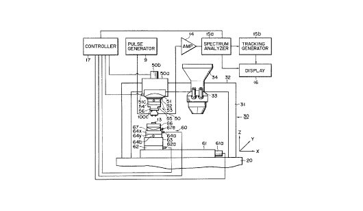
Fig. 1 schematically illustrates an overall block
diagram of an ultrasonic micro spectrometer ("USMS")
according to the first embodiment of the invention.
Fig. 2 illustrates a schematic arrangement of the ultra-
sonic micro spectrometer shown in Fig. 1.
As shown in Fig. 2, ultrasonic sensor 91 indepen-
dently executes transmission and reception of ultrasonic
waves, and is characteristically composed of the follow-
ing: a pair of ultrasonic transducers comprising a
concave-surface transducer lOa which is provided with a
concave ultrasonic transmission or reception surface and
a plane transducer lOb provided with a plane ultrasonic
transmission or reception surface. The concave trans-
ducer lOa and the plane transducer lOb may each be
employed as either an ultrasonic transmitter or
20~ 2
an ultrasonic receiver, respectively. The focal posi-
tion of the ultrasonic sensor 91 is determined by the
design of the transmission/receptlon surfaces. More
specifically the concave-surface transducer lOa is com-
posed of a curved piezoelectric film lOla made from zincoxide film, for example, and a pair of curved electrode
sheets 102a made from gold film sandwiching the curved
piezoelectric film lOla. The plane transducer lOb is
composed of a plane piezoelectric film lOlb made from
zinc oxide film, for example, and a pair of plane
electrode sheets 102b made from gold film sandwiching
the plane piezoelectric film lOlb. The piezoelectric
films lOla and lOlb respectively have a diameter of
several millimeters and a thickness of about 10 microns.
The curved electrode sheets 102a and the plane electrode
sheets 102b respectively have a diameter of about 2
millimeters.
The concave-surface transducer lOa and the plane
transducer lOb are respectively held by cylindrical
holders lOc. Each of these cylindrical holders lOc has
a diameter of about 10 millimeters and a length of
several centimeters. The concave-surface transducer lOa
and the plane transducer lOb are respectively manufac-
tured by sequentially laminating the component films on
a holder lOc made from resin by applying either vacuum
evaporation or a sputtering process. The component
films include a gold film 102a (102b), a zinc oxide film
20~30~2
- 12 -
sheets 102b made from gold film sandwlchlng the plane
piezoelectrlc fllm lOlb. The piezoelectric films lOla
and lOlb respectively have a dlameter of several milli-
meters and a thickness of about 10 microns. The curved
electrode sheets 102a and the plane electrode sheets
102b respectively have a diameter of about 2 millime-
ters.
The concave-surface transducer lOa and the plane
transducer lOb are respectively held by cylindrical
holders lOc. Each of these cylindrical holders lOc has
a diameter of about 10 millimeters and a length of
several centimeters. The concave-surface transducer lOa
and the plane transducer lOb are respectively manufac-
tured by sequentially laminating the component films on
a holder lOc made from resin by applying either vacuum
evaporation or a sputtering process. The component
films include a gold film 102a (102b), a zinc oxide film
lOla (lOlb), and an additional gold film 102a (102b).
Each of the holders lOc is secured inside a case
lOOc (described later on) in order that a constant angle
a can be maintained between the center line of the con-
cave transmission/reception surface of the concave-
surface transducer lOa and the center line of the plane
transmission/reception surface of the plane transducer
lOb, as shown in Fig. 2. A liquid coupler 12, substan-
tially consisting of water, is stored between a sample
13 mounted on a multiple-stage table 70 and the
2~3~2
- 13 -
waves are linearly converged. At the same tlme, the
transmitted waves are reflected by the surface of the
sample 13, and then, the reflected waves again propagate
through the liquid coupler 12 before being received by
the plane transducer lOb. The plane transducer lOb con-
verts the received reflected waves into electric
signals, and then outputs these electric signals to an
amplifier 14. The electric signals amplified by the
amplifier 14 are then delivered to a spectroanalyzer
15a, which analyzes the intensity of the reflected
waves. The result of this analysis is then delivered to
a tracking generator 15b, which analyzes the phase of
the reflected waves. The operating system the present
invention, comprising a controller 17, consecutively
performs the above-mentioned measuring processes while
sweeping the frequency of the burst signals supplied to
the transducer lOa. This eventually results in the for-
mation of a distribution of spectral intensity, desig-
nating the intensity of the reflected waves as a
function of frequency. In addition, a distribution is
generated of the phase of the spectrum, designating the
phase of the reflected waves as a function of frequency.
The distribution of the spectral intensity and the
distribution of the spectral phase are respectively
shown on a display screen 16.
As shown in Fig. 3, when the concave-surface trans-
ducer lOa is employed for transmission and the plane
~3~02
- 14 -
transducer lOb is employed for receptlon, ultrasonlc
waves are transmitted from the concave surface of the
concave-surface transducer lOa in the dlrection shown by
the arrows, so that the transmitted ultrasonlc waves
have a curved wavefront. Likewise, the plane surface
transducer 10~ receives ultrasonic waves having a curved
wavefront. The plane surface transducer lOb further
receives ultrasonic waves reflected from a single point
H. Nevertheless, as is clear from Figs. 3 through 5,
ultrasonic waves reflected from the point H, although
generally having a curved wave front, actually consist
of a plurality of combined plane-wave components E, ~,
and G containing a variety of wave fronts oriented in
different directions. AS is clear from Figs. 4 and 5,
those wave components E and G cannot effectively be con-
verted into electric signals because of phasewise inter-
ference generated on the surface of the piezoelectric
film 102b. Accordingly, among the variety of ultrasonic
waves reflected at the point H, only those specific
reflective waves having wavefronts designated by the
component F can reliably be received by the plane trans-
ducer lOb with any substantial effect. In other words,
this in turn indicates that the ultrasonic sensor 91
only outputs signals corresponding exactly to those com-
ponents reflected at a specific angle defined betweenthe plane transducer lOb and the sample 13. When the
plane transducer lOb is employed for reception of
- 15 - 2~3~Q2
generally having a curved wave front, actually consist
of a plurality of combined plane-wave components E, F,
and G containing a variety of wave fronts oriented in
different directions. As is clear from Figs. 4 and 5,
those wave components E and G cannot effectively be con-
verted into electric signals because of phasewise inter-
ference generated on the surface of the piezoelectric
film 102b. Accordingly, among the variety of ultrasonic
waves reflected at the point H, only those specific
reflective waves having wavefronts designated by the
component F can reliably be received by the plane trans-
ducer lOb with any substantial effect. In other words,
this in turn indicates that the ultrasonic sensor 91
only outputs signals corresponding exactly to those com-
ponents reflected at a specific angle defined betweenthe plane transducer lOb and the sample 13. When the
plane transducer lOb is employed for reception of ultra-
sonic waves, the angle of incidence must correspond to
the reflective angle, and in addition, even when the
plane transducer lOb is employed for transmission, the
angle of incidence also must correspond to the reflec-
tive angle.
As mentioned earlier, signals output from the
ultrasonic sensor 91 contain substantial intensity, and
in addition, these signals reflect the physical charac-
teristics, in particular elastic characteristics, of the
sample material present at the point H. Therefore, when
2~ 'j?j~2
reference to Figs. 6 through 8, even when the plane
transducer lOb is used for the transmission of ultraso-
nic waves and the concave-surface transducer lOa is
used for reception, a satisfactory effect identical to
the above case can also be achleved.
Referring to Fig. 6, when the plane transducer lOb
is employed for transmitting plane waves in the direc-
tion shown by the arrow, ultrasonic waves are transmit-
ted not only toward the point M, but are also emitted
toward a variety of points including M1 and M2, before
being reflected toward the concave surface transducer
lOa. Based on this phenomenon, it is probable that the
concave surface transducer lOa will receive not only
component K from the point M, but will also receive com-
ponents Kl and X2 of spherical or cylindrical wavesreflected from points Ml and M2, and a variety of other
polnts as well.
Referring now to Figs. 7 and 8, the wave component
X reflected toward the center of curvature of the con-
cave surface of the concave-surface transducer lOa is
effectively converted into electric signals by the con-
cave surface transducer lOa. On the other hand, wave
components Xl and X2 reflected by points Ml and M2 can-
not effectively be converted into electric signals as a
result of phasewise interference generated on the sur-
face of the piezoelectric film lOla. Accordingly, even
when the plane transducer lOb is employed for
2053002
- 17 -
belng reflected toward the concave surface transducer
10a. sased on thls phenomenon, lt ls probable that the
concave surface transducer 10a will receive not only
component K from the point M, but will also receive com-
ponents Kl and K2 of spherical or cylindrical waves
reflected from points Ml and M2, and a variety of other
points as well.
Referring now to Figs. 7 and 8, the wave component
K reflected toward the center of curvature of the con-
cave surface of the concave-surface transducer 10a is
effectively converted into electric signals by the con-
cave surface transducer 10a. On the other hand, wave
components Kl and K2 reflected by polnts Ml and M2 can-
not effectively be converted into electric signals as a
result of phasewise lnterference generated on the sur-
face of the piezoelectric film 101a. Accordingly, even
when the plane transducer 10b is employed for trans-
mission and the concave-surface transducer 10a is
employed reception of ultrasonic waves, a satisfactory
conversion effect can also be achieved, which is
substantially equivalent to the case, described above,
of using the concave surface transducer 10a for trans-
mission and the plane transducer 10b for reception of
ultrasonic waves.
As shown in Fig. 9, the ultrasonic sensor 91 can
precisely be ad~usted to the desired angle of incidence
merely by properly adjusting an angle ~l between a point
- 18 - ' 2 ~3 oa2
N orthogonally intersectlng the transmission/receptlon
surface of the plane transducer lOb and a point P ortho-
gonally lntersectlng the surface of the sample 13.
In addition, an optical microscope 33 (Flg. l) for
optically observing the sample 13 and a photographic
unit 34 for executing microscopic photography are
respectively secured to the horizontal frame 32. Since
the optical microscope 33 and the photographic unit 34
are well known and not always necessary for the ultraso-
nic micro spectrometer embodied by the invention, nodescription is given here.
The multiple-stage sensor driving mechanism 50 as
shown in Figs. 1 and 10, is secured directly below the
z-stage 50a. The multiple-stage sensor driving mecha-
nism 50 is composed of a plurality of stacked instru-
ments including the following: a ~-axial goniometer 51
which is installed on the top of the stacked assembly
and employed for establishing the angle of incidence; a
spacer 52 from which the sensor driving mechanism 50 is
supported; a ~-axial goniometer 53 which finely adjusts
the tilt angle of the ultrasonic sensor 91 in a direc-
tion traverse to the direction of inclination of the ~-
axial goniometer 51; an x-axial stage 54 which is
employed for correcting the focal position of the
ultrasonic sensor 91 in the x-axial direction; and a z-
axial spacer 55 which is employed for correcting the
focal position of the ultrasonic sensor 91 in the
2~30~2
-- 19 --
wheel (not shown) whlch ls lnstalled along a curved sur-
face 51d of the lncllnable table 51b to lncllne the
table 51b in the dlrectlon of the ~ axls through the
plurallty of components secured to the horlzontal sur-
face 51e directly beneath the inclinable table 51b, andfinally the ultrasonic sensor 91 ls stopped upon arrival
at the optimal angle of incidence compatible with a
selected measuring operation.
When establishing the optimal angle of incidence by
driving the ~-axial goniometer 51, it is desirable that
the ultrasonic waves reflected from the surface of the
sample 13 be effectively received by the ultrasonic
sensor 91. More specifically, it is desirable that the
plane formed between the surface of the sample 13 and
the ultrasonic sensor 91 by the incident waves and the
reflective waves be formed vertical to the surface of
the sample 13. To satisfy this requirement, the ultra-
sonic micro spectrometer according to the invention also
lncludes a ~-axial goniometer 53 secured to the bottom
horizontal surface 51e of the inclinable table 51d of
the ~-axial goniometer 51 via the spacer 52. The ~-
axial goniometer 53 inclines the ultrasonic sensor 91 in
the direction of an axis ~. The ~-axial goniometer 53
is provided with a drive unit 53a and an inclinable
table 53b identical to the drive unit 51a and the incli-
nable table 51b provided for the ~-axial goniometer 51.
- In addition, the main shaft ~not shown) inside of the
- 20 - 2~3~02
drive unit 53a may be manually drlven by means of a knob
53c coupled with the maln shaft. When the operator
manually operates the knob 53c, the ultrasonic sensor 91
is lnclined in the dlrection of the ~ axis through the
components secured between the bottom horlzontal surface
53d of the incllnable table 53b and the ultrasonic sen-
sor 91, before eventually being held at an optimal angel
of incidence.
Furthermore, when inclining the ultrasonic sensor
91 by operating the ~-axial goniometer 51, it is
desirable that the focus of the ultrasonic sensor 91 be
exactly positioned on the center axial line (in the
- direction vertical to the surface of the sample 13) and
at the point of inclination CO of the 0-axial goniometer
51. The point of inclination CO refers to the point
about which the ~-axial goniometer 51 inclines the sen-
sor 91 with respect to the surface of the sample 13, as
shown in Fig. 10. This permits the focus to be held at
a constant position against the sample 13 independent of
the variation of the angle of incidence. To achieve
this, the ultrasonic micro spectrometer embodied by the
invention includes an X-axial stage 54 and a Z-axial
spacer 55 disposed directly beneath the ~-axial
goniometer 53. The X-axial stage 54 corrects the focal
position of the ultrasonic sensor 91 in the direction of
the X axis. More specifically, the X-axial stage is
slidably disposed on the plane surface 53d directly
- 21 - 2053~02
below the lncllnable table 53b of the ~-axlal goniometer
53, so as to be slidable in the dlrection of the X axis
by any conventional means. In addition, the focal posi-
tion of the ultrasonic sensor 91 can properly be
ad~usted in the X-axial direction by manually sliding
the X-axial stage 54.
The Z-axial spacer 55 is secured to the X-axial
stage 54 and brings the Z-axial-directional focus of the
ultrasonic sensor 91 into accord with the point of
inclination C0 of the ~-axial goniometer 51. The
Z-axial spacer 55 may be elongated and contracted in the
direction of the Z axis when the operator manually
operates the knob 53c. By finely adjusting the X-axial
stage 54 and the Z-axial spacer 55, the focal position
of the ultrasonic sensor 91 is brought into perfect
accord with the point of inclination C0 of the 0-axial
goniometer 51.
As shown in Figs. 1 and 10, a multiple-stage table
60 is mounted on the base 20 of the ultrasonic micro
spectrometer. The multiple-stage table 60 is composed
of a plurality of stacked instruments including the
following: a positioning X-stage 61 placed on the base
20, a positioning Y-stage 62, a rotary stage 63, an
XY-stage 64, and a dual goniometer 65, respectively.
It is desirable that the upper surface of the
sample 13 mounted on the upper surface of the multiple-
stage table 60 be maintained level with the XY drive
~2 ~ ~ J~
- 22 -
Z-axial spacer 55 may be elongated and contracted in the
dir0ction of the Z axis when the operator manually
operates the knob 53c. By finely ad~usting the X-axial
stage 54 and the Z-axial spacer 55, the focal position
5 of the ultrasonic sensor 91 is brought into perfect
accord with the point of inclination C0 of the ~-axial
goniometer 51.
As shown in Figs. 1 and 10, a multiple-stage table
60 is mounted on the base 20 of the ultrasonic micro
spectrometer. The multiple-stage table 60 is composed
of a plurality of stacked instruments including the
following: a positioning X-stage 61 placed on the base
20, a positioning Y-stage 62, a rotary stage 63, an
XY-stage 64, and a dual goniometer 65, respectively.
It is desirable that the upper surface of the
sample 13 mounted on the upper surface of the multiple-
stage table 60 be maintained level with the XY drive
surface of the multiple-stage table 60. To achieve
this, a dual goniometer 65 is provided for the multiple-
stage table 70. The dual goniometer 65 is composed of
an upper sample mounting table 66 and a lower goniometer
67. More specifically, in order that the sample
mounting table 66 can be moved in conjunction with the
inclinable table 67a of the goniometer 67, the plane
surface 66a at the bottom of the sample mounting table
66 is secured to the upper plane surface 67b of the
inclinable table 67a.
20~3002
- 23 -
the sample 13 in the direction of x axis and a y-stage
64y which moves the sample 13 in the dlrectlon of y
axis. The x and y stages 64x and 64y are respectlvely
displaced by any conventional system, and preferably by
stepping motors 64a and 64b.
In order to enable the ultrasonic micro spectro-
meter to properly deal with a variety of measuring
requirements, it is desirable that the measuring system
be provided with a specific mechanism capable of
rotating either the sample-mounting table 66 or the
ultrasonic sensor 91 relative to each other in a plane
parallel to the XY-drive surface of the multiple-stage
table 60. To achieve this, the ultrasonic micro
spectrometer embodied by the invention is provided with
a rotary stage 63 disposed directly below the XY stage
64. The rotary stage 63 includes a circular turntable
63a capable of being rotated around a center axial line
C2. The circular turntable 63a is supported by a sup-
porting member 63b via a supporting roller 63c. A worm
gear 63e is provided on the circumferential surface of a
downward projection 63d below the circular turn table
63a. A main shaft 63g is provided on which a worm wheel
63f is mounted, and the worm wheel 63f is engaged with
the worm gear 63e and is rotated by a stepping motor
63h. Therefore, the circular turntable 6~a may be
rotated by the rotation of the worm wheel 63f. The cir-
cular turntable 63a is capable of turning a full 360~.
2~3~2
- 24 -
ultrasonlc sensor 91 relatlve to each other ln a plane
parallel to the XY-drive surface of the multiple-stage
table 60. To achieve this, the ultrasonic mlcro
spectrometer embodled by the inventlon is provlded with
a rotary stage 63 dlsposed directly below the XY stage
64. The rotary stage 63 includes a circular turntable
63a capable of being rotated around a center axial line
C2. The circular turntable 63a is supported by a sup-
porting member 63b via a supporting roller 63c. A worm
gear 63e is provided on the circumferential surface of a
downward pro;ection 63d below the circular turn table
63a. A main shaft 63g is provided on which a worm wheel
63f is mounted, and the worm wheel 63f is engaged with
the worm gear 63e and is rotated by a stepping motor
63h. Therefore, the circular turntable 63a may be
rotated by the rotation of the worm wheel 63f. The cir-
cular turntable 63a is capable of turning a full 360~.
While the rotary stage 63 is rotated with the stepping
motor 63h, and simultaneous with the delivery of an
optional number of pulses from the controller 17 to the
stepping motor 63h, the controller 17 also instructs the
spectroanalyzer 15a to initiate the introduction of
electric signals.
The ultrasonic micro spectrometer according to the
present invention performs measuring and evaluation pro-
cesses with respect to a specific minimal region of the
sample 13 by varying the angle of incidence. However,
20~3002
- 25 -
lndependent of the varlatlon of the angle of lncldence,
it ls 0ssential for the system to ensure that the mlnl-
mal reglon constantly colncldes wlth the focus of the
ultrasonlc sensor 91. In other words, lt ls essentlal
for the system to ensure that the center axlal llne C2
of the circular turntable 63a perfectly colncldes with
the focal llne Cl of the ultrasonic sensor 91. To
achieve this, the ultrasonlc mlcro spectrometer embodled
by the invention ls provlded wlth a posltlonlng Y-stage
62 and another positioning x-stage 61 to displace the
rotary stage 63 in the direction of the Y and X axes.
The positioning Y-stage 62 is slidably moved in the
dlrection of the Y axis above the positioning X-stage 61
by a conventional means, preferably, by a stepping motor
62a.
The positioning X-stage 61 disposed below the posi-
tlonlng Y-stage 62 not only posltlons the turntable 63a,
but also is capable of displacing the sample 13 to a
- position below the optical mlcroscope 33. The position-
ing X-stage 61 is slldably moved in the direction of the
X axis by a stepping motor 61a.
The ultrasonic micro spectrometer according to the
present lnventlon includes a sc~nn1ng means composed of
the XY-stage 64 for directly displacing the sample 13.
However, sc~nn~ng movement may also be provided on the
side of the ultrasonic sensor 91 and~or with the assis-
tance ultrasonic sensor 91. For example, if the sample
.,;
2~0a2
- 26 -
13 has a large slze, or in the event that the llquid
coupler 12 cannot properly be mounted on the surface of
the sample 13, then it is necessary to mount a water
container, filled with the liquid coupler 12, on the
sample mounting table 66, and place the sample 13 inside
the water container. In this case, if the scanning
XY-stage 64 on the side of the sample 13 were driven
quickly, then the liquid coupler 12 would possibly slosh
out of the water container. To prevent this, in the
case of a sample that cannot easily be mounted with the
liquid coupler disposed on the sample, or in the case of
a large sample, then the ultrasonic sensor g1 may be
disposed such that the sensor itself performs the
scanning operations in the directions of the x and Y
axes. Furthermore, scanning operations may be performed
in the X and Y directions by displacing the ultrasonic
sensor 91 at a fast speed in one of the X or Y direc-
tions, ~hile simultaneously displacing the sample 13
slowly in the other direction. In this case, the
scanning movement on the part of the ultrasonic sensor
91 may be provided at a fast speed by applying a "voise"
coil motor, for example. Furthermore, in order to pro-
vide scanning movement on the part of the ultrasonic
sensor 91, it is essential for the USMS system to
install such a scanning means above the ~-axial
goniometer 51.
The ultrasonic micro spectrometer according to the
~3~a2
- 27 -
present inventlon is provlded with a rotary stage 63 on
the slde of the sample 13 so that the sample can be
rotated. However, instead of thls arrangement, a means
for rotating the ultrasonlc sensor 91 may also be pro-
vided. In thls case, ln order that the center axis ofthe rotating means accurately coincides with the focal
line Cl, it is essential for the USMS system to provide
such a rotating means above the e-axial goniometer 51,
or at a position higher than the scanning unit provided
,:
on the side of the ultrasonic sensor 91.
In order to precisely ad~ust the focal depth of the
ultrasonic sensor 91, the USMS system may provide a z-
stage 50a (Fig. l) driven in the direction of the z axis
vertical to the XY drive surface on the side of the
. ,
~-~ 15 ultrasonic sensor 91. When lnstalling the Z-stage 50a
on the side of the ultrasonic sensor 91, it is essential
, ~
that the Z-stage 50a be disposed above the O-axial
goniometer 51. This is because in order to vary the
,~
distance between the sample 13 and the ultrasonic sensor
91 and to bring the focus of the sensor into perfect
coincidence with the point of inclination CO, the sensor
driving mech~n;sm 50 must be completely displaced as a
; whole.
Fig. llA schematically illustrates a block diagram
of the ultrasonic micro spectrometer according to a
second embodiment of the invention. If the USMS system
uses wide-band pulse signals which are substantially
2a~30~
~ 28 -
the structure of the ultrasonic sensor 92. Accordlngly,
the following description refers solely to the ultraso-
nic sensor 92.
The ultrasonic sensor 92 i5 provided with a concave
surface transducer 101c and a plane transducer 101d.
The concave surfac0 transducer 101c consists of the
following: A transmission/reception assembly unit 10b
composed of a plane piezoelectric film 101b and a pair
of plane electrodes 102b sandwiching the plane piezo-
electric film 101b therebetween; and a delay element llc
having a concave transmission/reception surface at the
tip thereof, wherein the delay element llc is bonded to
the transmission/reception assembly unit 10b to complete
the formation of the plane transducer 101d. On the
other hand, a plane transducer 101d consists of a
transmission/reception assembly unit 10b and a delay
element lld having a plane transmission/reception sur-
face on the tip thereof, wherein the delay element lld
is bonded to the transmission/reception assembly unit
10b to complete the formation of the plane transducer
101d. The concave surface transducer 101c and the
plane transducer 101d are respectively manufactured by
sequentially laminating a gold film 102b, a zinc oxide
film 101b, and another gold film 102b on the delay ele-
ment llc or lld by applying either vacuum evaporation or
a sputtering process. The delay element llc or lld may
be fabricated from melted quartz, for example.
2~30~2
- 29 -
The concave surface transducer lOlc and the plane
transducer lOld are respectlvely held by a holder member
lOOc.
Except for the two differences mentloned below, the
ultrasonic sensor 92 according to the third embodiment
of the invention functions identically to the ultrasonic
sensor 91 described previously. First, the ultrasonic
sensor 92 differs from the sensor 91 in that the sensor
92 generates convergent ultrasonic waves which converge
dependent on the difference between the velocity of
sound in the delay element and the velocity of sound in
the transmission liquid 12. Secondly, the focus of the
ultrasonic sensor 92 deviates slightly in a direction
away from the delay element llc and against the center
of curvature of the concave surface of the delay element
llc .
As with the ultrasonic sensor 91 according to the
first embodiment, the ultrasonic sensor 92 precisely
measures physical characteristics, in particular elastic
characteristics, within a minimal region of the sample
independently of the orientation of the transmission/
reception surface of the concave surface transducer lOlc
of the ultrasonic sensor 92.
Figs. 12 and 13 respectively illustrate the struc-
ture of the ultrasonic sensors employed in the ultraso-
nic micro spectrometer according to the fourth
embodiment of the invention. The ultrasonic sensors 93
2~300~
- 30 -
and 94 according to the fourth embodlment of the lnven-
tion are respectively composed of a concave surface
transducer and a plane transducer, wherein either of
these ultrasonic sensors may be provided with a delay
element llc or lld. The other transducer has a struc-
ture identical to that of the ultrasonic sensor 91
according to the first embodiment.
Fig. 14 illustrates the structure of an ultrasonic
sensor 95 employed in the ultrasonic micro spectrometer
according to the fifth embodiment of the invention. The
ultrasonic sensor 95 according to the fifth embodiment
comprises a delay element lle having an integrally com-
bined concave surface lOle and a plane surface lOlf.
Although the delay element is made from the same
material as that of the preceding delay elements llc
and lld, the delay element lle is provided with both
recessed and plane transmission/reception surfaces. It
is further evident that the ultrasonic sensors according
to the fourth and fifth embodiments of the invention are
capable of achieving results comparable to those which
are achieved by the preceding ultrasonic sensors accord-
ing to the first through third embodiments.
The longitudinal width L of the plane transducers
according to the first through fifth embodiments should
be selected so as to satisfy the following expression
(1), shown below:
L > (l/sin~) ~ (Vw/~) (1)
20~30~2
- 31 -
where vw deslgnates the veloclty of sound ln the llquld
coupler, ~ deslgnates elther the tlme-base frequency of
an ultrasonlc wave transmltted from the ultrasonlc sen-
sor or the dlp frequency based on the distributlon of
spectral intensity, and ~ designates a value expressing
the range of incldent angles whlch may be selected for
the ultrasonlc sensor.
In relation to the flrst embodiment, a speclfic
example shall be descrlbed below, in which the concave
surface transducer lOa is employed for the transmlsslon
of ultrasonic waves, and wherein the plane transducer is
employed for receptlon of ultrasonic waves.
Referring to Fig. 15, the angle of incidence ~ of
the plane transducer lOb with respect to the surface of
the sample 13 is defined between a normal line Nl of the
plane transducer lOb and a normal line N2 on the surface
of the sample 13. As shown in Fig. 15, assuming that
;~ the ultrasonic wave received by the plane transducer lOb; contains wave components which deviate from the angle of
,~ 20 incidence ~ by an angle a, in this case, it is known
that the ultrasonic sensor 91 outputs signals corre-
sponding to ultrasonic waves as shown in Figs. 16 and
; 17. More specifically, in the case where a = o, ultra-
sonlc waves are vertically transmitted to the plane
transducer lOb. If, however, the ultrasonic transducer
lOb has a substantial width L, even if the angle a were
narrow, the intensity of the ultrasonic waves output
2~3002
- 32 -
from the ultrasonic sensor declines sharply as the angle
devlates from the incident angle ~. Generally, the out-
put intensity is reduced to zero when the angle a is
equal to ~. It is therefore clear from Fig. 18 that
should satisfy the equation (2) shown below:
~ = sin~l(A/L) (2)
where A designates the ultrasonic wavelength, and
further where A = Vw/~. As a result of the phasewise
interference whlch takes place across the width of the
plane transducer lOb, the ultrasonic wave components
which are deviated from the incident angle ~ by the
angle ~, according to equation (2), are reduced to zero.
In other words, ~ defines a parameter whereby the ultra-
sonic sensor 91 can output only those ultrasonic wave
components having a substantial intensity falling within
a range ~ + ~. When ~ is defined as described above,
the range of incident angles available for the ultraso-
nic sensor are selected accordingly, and the width L for
the plane transducer lOb incorporating such a incident
angle range is computed based on the above equations (1)
and (2).
The output characteristics of the ultrasonic sen-
sor, as well as the above expressions (1) and (2), may
be satisfied even in the case where a plane transducer
is employed on the transmission side of the ultrasonic
sensor. Further, similar performance is achieved
whether or not delay elements are employed in either or
20~3~02
- 33 -
both of the ultrasonlc transducers.
Speclfic examples of the operation of the ultraso-
nic mlcro spectrometer according to the present inven-
tion shall be described below.
Preparation for a Measuring Operation:
Initially, an operator mounts the sample 13 on the
upper table 66 of the multiple-stage table 60. When
positioning the multiple-stage table 60 in the direction
of the X-axis, the X-stage 64x is displaced through
operation of the stepping motor 64a. Similarly, when
positioning the multiple-stage table 60 in the direction
of the Y-axis, the Y-stage 64y is displaced through
operation of the stepping motor 64b. In order to set a
desired angle of incidence, the inclinable table 51b of
the ~-axial goniometer 51 is tilted through operation of
the stepping motor 51c.
Measurement of the Phase Velocity of Elastic
Surface Waves:
In order to measure the phase velocity of an
elastic surface wave, ordinarily a non-laminated sample
is used. After completing the preparatory steps men-
tioned above, the pulse generator 9 is activated to feed
a burst signal to the concave surface transducer 10a
while the frequency of the burst signal is swept across
a predetermined range. Ultrasonic waves transmitted to
the sample by the concave surface transducer 10a are
reflected on the surface of the sample 13, and the
2~3~
- 3~ -
reflected waves are received by the plane surface trans-
ducer lOb, which converts the received waves into
electric signals. The spectroanalyzer 15a analyzes the
frequencies of the generated electric signals, and forms
a distribution of the spectral intensity as a function
of frequency. Next, based on the distribution of
spectral intensity, data designating a relationship
between the intensity of the ultrasonic waves and the
angle of incidence are shown on the display screen 16.
The USMS system then repeats the above operations while
varying the angle of incidence, and based on a predeter-
mined relationship, the control system precisely com-
putes the angle of incidence ~r at which the intensity
of the ultrasonic wave is minimized, as shown in
Fig. l9.
Based on the computed angle of incidence ~r, the
control system then computes a phase velocity vp of the
elastic surface wave by applying the following equation
(3), shown below:
vp = vw/sin~r (3)
wherein Vw designates the velocity of sound in the
liquid coupler 12.
It is well known that the phase velocity vp of
an elastic surface wave provides an important parameter
which quantitatively expresses the elastic property of
the sample.
Furthermore, as described below, the phase velocity
- 35 - 20~30~2
varying the angle of incidence, and based on a predeter-
mined relationship, the control system precisely com-
putes the angle of lncidence ~r at which the intensity
of the ultrasonic wave is ~n~m1zed, as shown ln
Fig. 19.
Based on the computed angle of incidence ~r, the
-control system then computes a phase velocity Vp of the
elastic surface wave by applying the following equation
(3), shown below:
Vp = Vw/sin~r (3)
wherein Vw designates the velocity of sound in the
liquid coupler 12.
It is well known that the phase velocity Vp of
an elastic surface wave provides an important parameter
which quantitatively expresses the elastic property of
the sample.
Furthermore, as described below, the phase velocity
Vp of the elastic surface wave can also be computed by
applying a distribution based on the phase of the
spectrum. More specifically, the result of the analysis
executed by the spectroanalyzer 15a is delivered to a
tracking generator 15b, which then forms a distribution
of the phase of the spectrum dependent on incident
angle. Based on the distribution of the phase of the
spectrum, data designating the relationship between
phase and incident angle, as well as the relationship
between phase and intensity of the ultrasonic waves, are
- 36 - 2~3~a~
for which there is no specific angle of incldence ar, as
shown in Fig. l9, at which the lntensity of the ultraso-
nic wave becomes a minimum. Therefore, in contrast to
the case of measuring only intenslty of the ultrasonic
wave, the ultrasonic micro spectrometer according to the
present invention can effectively be used with a greater
variety of specimens, by observing the distribution
between the angle of incidence and the phase of the
spectrum.
The ultrasonic micro spectrometer according to the
present invention is capable of performing a variety of
measurements on a sample based on the distribution of
the phase of the spectrum in order to identify whether
the sample is made from a non-laminated material or not,
for example. This is because, if the angle of incidence
~c remain constant across all frequencies, then it can
be determined that the sample does not contain a lami-
nated structure formed from different layers. On the
other hand, if the angle of incidence ~c varies at dif-
ferent frequencies, then the ultrasonic micro spectro-
meter can identify the sample as having a laminated
structure. In the latter case, the ultrasonic micro
spectrometer can also generate useful data expressing
the elastic characteristics and strata structure of the
sample in detail, by displaying various graphs on the
display screen designating relationships between dif-
ferent frequencies and incident angles ~c.
2~3Q~2
Measurement of the Distribution Curve for Elastic
Surface Waves:
By way of a test example, the inventors measured
the distribution curve of an elastic surface wave
applied to a sample 13 comprising plated or coated film
layers formed on a substrate. Processes identical to
the measurements of the phase velocity of elastic sur-
face waves, as described above, were performed at a
variety of different frequencies. Finally, the ultraso-
nic micro spectrometer graphically displayed the rela-
tionship between ultrasonic frequencies and the angle of
incidence at which the variation in phase was detected,
as shown in Figs. 22 and 23. Generally, this rela-
tionship is referred to as the ~dispersion curve~' and
provides an important source of data for characterizing
the elastic properties of the sample 13.
Measurement of Layer Thickness:
In order to measure the thickness of laminated
layers, the inventors used a sample 13 comprising plated
or coated film layers formed on a substrate.
While measuring the thickness of the laminated
layers of the sample 13 at a specific incident angle ~1,
the reflective intensity of the ultrasonic waves was
mtn~m~zed, while simultaneously the specific frequency
fc at which the phase of the ultrasonic waves started to
vary was determined. In particular, the frequency com-
ponent fc has a specific relationship to layer thickness
- 38 - 20~30~
"d" as shown below:
fc x d = c (5)
where C designates a constant determlned by the elastic
characterlstics of the substrate, the laminated layers,
the li~uid coupler, and the angle of incidence ~1 the
ultrasonic waves.
By using a sample of the same type as the sample 13
but having a known layer thickness, the value of the
constant C, shown above, can preliminarily be computed
before actual measurement of the layer thickness of the
sample, thereby calibrating the apparatus. Therefore,
if the angle of incidence ~ is held constant, then the
layer thickness "d" of the sample can be computed by
applying the above equation.
If a false "Sezawa" wave becomes excited as an
elastic surface wave on a sample containing laminated
film layers, then the energy of the surface wave also
leaks in the direction of the depth of the laminated
sample, thus lowering the reflective intensity.
Measurement of Anisotropy:
To measure anisotropy, as anisotropic sample such
as a crystal or an elongated film is employed as the
sample 13. The phase velocity of the elastic surface
waves on the surface of the anisotropic sample is
variable according to the direction of propagation of
the elastic surface waves. More particularly, depending
on the direction of propagation of the elastic surface
2~3~
- 39 -
waves, elther the angle of lncidence ~r at which the
intensity of ultrasonlc waves becomes a minimum, or the
angle of incidence ~c at which a phase shift occurs, is
sub~ect to varlation. This variation in turn signifies
that either the symmetry of the crystal or the direction
and extent of elongation of the film can be measured by
detecting a variation of either the angle of incidence
~r or the angle of incidence ~c.
While performing the preparatory processes before
measurement of anisotropy, the positioning X-stage and
the positioning Y-stage are respectively moved to preci-
sely align the focal line Cl of the ultrasonic sensor
with the center axial line C2 of the turntable 63a of
the rotary stage 63. While maintaining this position,
the USMS system detects the angle of incidence ~r by
rotating the rotary table 63. Next, based on equations
(3) and (4) cited earlier, the USMS system can measure
the anisotropy of the phase velocity of elastic surface
waves in the direction of propagation of the elastic
: 20 surface waves on the sample 13.
There has been described above various specific
examples for operating the USMS system of the present
invention in order to perform a variety of measurement
functions. In order to reliably perform the measurement
processes described above, it is essential that the USMS
system be capable of accurately detecting the angle of
incidence 0 of the ultrasonic waves which travel between
~3~3~
- 40 -
the transmission/reception of the plane transducer and
the surface of the sample.
Fig. 24 illustrates an example of the USMS system
incorporating means for measuring the angle of incldence
~. A laser angular meter 70 transmits a laser beam Ll to
the transmission/reception surface of the plane trans-
ducer lOb. The emitted laserbeam Ll is then reflected
by the transmission/reception surface of the plane
transducer lOb, and the reflected laser beam L2 is
received by the laser angular meter 70 so that the angle
of incidence ~ can be detected. An optical element,
for example a prism, may optionally be disposed in the
light paths of the laser beams Ll and/or L2 for
directing the laser beams.
When operating the USMS system incorporating the Z-
axial stage 50a, the angle of incidence ~ can be com-
puted by applying the equation shown below:
~ = cos~lt~P(f)/Z) x (V/4~f) (6)
where Z designates the vertical distance between the
ultrasonic sensor 91 and the surface of the sample 13,
P(f) designates the phase at an optional frequency com-
ponent "f", and V designates the velocity of sound in
the liquid coupler 12. By expressing the above rela-
tionship between Z and P(f) as a linear graph, ~P(f)/Z
can be computed as the slope of the line defined by the
above equation.
Fig. 25 schematically illustrates a block diagram
2~3002
- 41 -
of incidence 3 can be detected. An optlcal element,
for example a prlsm, may optlonally be dlsposed in the
light paths of the laser beams Ll and/or L2 for
directing the laser beams.
When operating the USMS system incorporating the Z-
axial stage 50a, the angle of incidence o can be com-
puted by applying the equation shown below:
~ = cos~l(~p(f)/z) x (V/4~f) (6)
where Z designates the vertlcal distance between the
ultrasonic sensor 91 and the surface of the sample 13,
P(f) designates the phase at an optional frequency com-
ponent llf'l, and V designates the velocity of sound in
the liquid coupler 12. By expressing the above rela-
tionship between Z and P(f) as a linear graph, ~P(f)/Z
can be computed as the slope of the line defined by the
above equation.
Fig. 25 schematically illustrates a block diagram
of the USMS system according to the sixth embodiment of
the invention. According to this embodiment, the focus
, .~
of the ultrasonic sensor is determined by the curvature
of the concave surface of the concave surface transducer
lOa, and the angle of inclination is determined by the
degree of inclination of the plane transducer lOb.
Therefore, although only the plane transducer lOb is
lnclined with respect to the sample, while the axis of
the concave transducer lOa remains vertical as shown in
Fig. 25, according to the sixth embodiment the USMS
2~30~2
- 42 -
80 havlng substantlally the same lnternal structure as
that of ~-axlal goniometer 51 employed in the sensor
drivlng mechanism 50 of the preceding embodiments. The
~-axial goniometer 80 is secured to the horizontal frame
32 via a supporting member 82. According to the slxth
embodiment of the invention, varlous measuring opera-
tlons can be precisely performed with respect to a spe-
cific target region of the sample 13 by setting the
lncident angle wlthln a wldely applicable range.
An example of a test performed by the inventors for
measuring the critical angle Or for exciting a
"Rayliegh" wave having a single degree of precision on
the sample 13 using the USMS system of the sixth embodi-
ment shall now be described.
While performing the test, the inventors used a
sample 13 made from melted quartz, and water was used as
the liquid coupler 12. A concave surface transducer
lOa having a cylindrical concave surface having a radius
of 5 mm and a half angle aperture of 20 degrees was
employed. In the course of the test, the pulse genera-
tor 9 was set to deliver a pulse signal having a fre-
quency of 50 MHz to the concave surface transducer lOa.
Based on a velocity of sound in water of 1500
meters per second, and an ultrasonic frequency of 50 x
106 Hz, the width L of the plane transducer lOb was
selected to be 17.2 mm according to the equation (1):
L = l/sin(l.0) ~ (1500/50 x 106) = 17.2 mm
3~a2
- ~3 -
Based on the above condltlons, the lnventors
measured the distrlbutlon of the phase spectrum of the
reflected waves by manually operating the ~-axlal
goniometer 51 and varying the angle of incldence of the
plane transducer wlth respect to the sample ln a range
from 20 to 30 degrees. Finally, the above test revealed
the results shown in Fig. 26. More specifically, as
shown in Fig. 26, the phase of the reflective wave
experienced a clear shift at an incident angle of ~ =
23~. Based on this data, the inventors were able to
confirm that the critical angle ~r for generating exci-
tation of a "Rayleigh" wave in melted quartz occurred in
; the range from 23~ to a maximum of 24~.
It should be apparent that the above described
ultrasonic micro spectrometer possesses numerous advan-
tages for enabling the measurement of a variety of
samples, and that the invention therefore possesses
~ important commercial and analytical utility. It should
: further be understood that the specific form of the
invention hereinabove described is intended to be repre-
sentative only, as certain modification within the scope
of these teachings will become apparent to those of
skill in the art.
Accordingly, reference shall be made to the follow-
ing claims in determining the full scope of the inven-
tion.