Note: Descriptions are shown in the official language in which they were submitted.
20~319~
Continuously-Operatinq Press
The present invention relates to a continuously-operating
press in accordance with the preamble to Patent Claim 1.
The industrial application of such pressing systems has
demonstrated that the best values for characteristics such as
lateral tensile strength and flexural strength in particle
board, for example, can be achieved if the material-to-be-
pressed is compressed gradually with very high pressure from
the beginning of the pressing process up to the point that
maximum pressing force is applied. This method ensures the
constant and rapid transfer of heat from the outside to the
inside inside the particle structure of the material-to-be-
pressed. Furthermore, as a result of the heat transfer
initiated by the immediate application of pressure, it is
possible to avoid premature hardening of the surface of the
material-to-be-pressed. Prehardening implies greater wear; in
other words, the favorable technical qualities, which can be
attained by use of the above system, also ensure optimal cost
savings (less wear). These requirements should be met by
continuously-operating presses which, in their entry region,
which is to say in the zone adjoining the entry gap, whose
size is set by adjusting the deflection rollers for the press
bands, permit creation of a pressure profile that suits the
type of pressing operation as well as the operational
parameters of the press.
Normally, the entry gap is set to a stationary wedge-
shape whose cross-section decreases in the process direction
of the press, whereby more or less pressure can, according to
need, be applied to the incoming particle mass. In a press
that is provided with roller chains, an example of which is
disclosed in DE-OS 22 05 575, pressure elements are arranged
between the introductory pressure roller and the press gap and
the deflection drums for the press bands and, in this region,
exert upon the material-to-be-pressed a pressure that can be
regulated according to operating requirements, whereby the
entry gap can be adjusted wider or narrower, according to
need. In this prior art version, the steel band is merely
2 20 5 3 1 9 5
guided upon the drums in the front region, following which
is a pressureless sliding section, followed in turn by the
actual pressure-roller contact, from which point the
pressure is gradually increased from 0 to the maximum
pressure.
One disadvantage of the above-mentioned method is that
following the first contact with the material-to-be-pressed,
whereat pressure is applied by the deflection drums and by
the pressure members, pressure is relieved twice, which
introduces the danger that, through even the slightest
expansion (breathing) of the particle mass, the surface-
hardened and therefore brittle surface layer can be damaged
by lateral ripping which reduces the overall structural
strength of the finished particle board.
A further disadvantage of the above method is that the
roller rods, although introduced orthogonally into the entry
region, lose their predetermined, consistent travel specifi-
cations including regular inter-rod spacing, upon entering
the compression build-up region, due to improper particle
compaction which can occur for example, during particle
board production, a condition that can lead to individual
roller rods colliding with and damaging each other.
The object of the present invention, therefore, is the
creation of a continuously-operating press wherein a
pressure profile can be adjusted to correspond to the
variable compression angle inside the entry zone for the
purpose of pressing particle mat having different degrees of
compaction, and whereby a product can be produced possessing
consistently high surface qualities and physical
characteristics even given variations in the height and type
of compaction of the particle mat entering the press.
According to one aspect of the invention, there is
provided continuously-operating press suitable for use in
the production of particle board, fibre board and similar
products made of wood material, whereby flexible endless
steel bands, which circulate about a press bed or press top
over drive rollers and deflection rollers, serve to transmit
pressing force to and pull through said press the material
to be pressed and, being separated by an adjustable press
A
,
2~ 5 3 ~ 9 5
2a
gap, are supported by means of roller rods whose axes run
across the direction of movement of said steel bands,
against both press top and press bed, and whereby an angle
of an entry gap leading to said press gap can be adjusted by
means of adjustment mechanisms arranged in the press bed and
press top and whereby furthermore the material-to-be-pressed
is transferred from a transfer plate via a transfer nose of
a loading belt onto the lower steel band, whereby, each of
entry-side heating plates, which pivot about axis of
rotation and form an entry gap, together with entry systems
of the press bed and press top comprises a roller rod
alignment region (c), a curved material-to-be-pressed pre-
compression region (a) and a straight compression region
(b), whereby the support in entry region (c, a, b) for the
roller rods, which extends from entry tangent up to the
beginning (e) of the high pressure region applies steadily
increasing frictional but flexible pressure in the range of
G bar to maximum pressure by means of a plurality of
hydraulic support members for roller rod alignment region
(c), for material-to-be-pressed pre-compression region (a),
for compression region (b) is sectioned into two rigid
regions wherein frictional pressure is applied, for which
purpose an adjustable pressing force profile and variable
compression angle can be regulated by computer-controlled,
servo-hydraulic means and whereby from the beginning of the
roller rod alignment region (c) up to 1/4 of the material-
to-be-pressed pre-compression region (a), the pressing force
is steadily increased from 0 to maximum pressure/4, whereby
the entry region (c, a, b) is, beginning from the last third
of the roller rod alignment region "c" and in the material-
to-be-pressed pre-compression region "a", designed with a
curvature RE whose radius is equal to or up to twice the
radius of deflection drum RU.
The proposed particle mass introduction system
therefore advantageously enables the adjustment of the
correct compression angle and the corresponding pressure
profile on both top and bottom for varying surface layer
distributions of particulate and for varying degrees of
particle mass
-
3 20a319~i
compaction i.e. varying particle density, structure and
bonding agent quantity, by means of which method maximum
pressing force can consistently be applied at the end of the
entry region, or rather, at the beginning of the high pressure
region. Furthermore, a more acute compression angle enables a
more rapid application of higher pressure at pressing material
contact point PK at which point 25% of the maximum pressing
force can be developed.
A further advantage of the present invention is that the
roller rods are, during their introduction into the roller rod
alignment region "c" and in the first part (a/4) of the
pressing material pre-compression zone "a", not subjected to
any negative influences by the material-to-be-pressed and are
thus able to roll with consistent inter-rod spacing, in an
absolutely orthogonal manner, up to the point at which a
clamping force of approx. 12 bars (25% of maximum pressing
force) is applied to the roller rods.
After transiting both roller rod alignment section "c"
and 25% of pressing material pre-compression section "a", the
pressing material reaches pressing material contact point PK
and is rendered incapable of causing the roller rods to shift,
since the latter are, after leaving the roller-rod alignment
section "c", subjected, by means of hydraulic support members,
to relatively high clamping pressure in the curved pressing
material pre-compression region "a" between the steel band and
the curved heating plate region.
Varying upper and lower compression angle ~ from 0 to 3~
and a maximum of 4~ causes a shift in the point of the entry
tangent from the roller rod introduction sprocket and
deflection radius RE of the pressing material pre-compression
region "a" to the deflection radius RU of the deflection drum
through angle ~. Thus, changes in the size of the compression
angle in compression region "b" affect the size of the size of
entry tangent angle B for the steel band in roller rod
alignment region "c". The resilient bearing of the roller rod
introduction sprockets permits, in this zone, the application
of frictional contact pressure from 0 to approx. 2-4 bars up
2~3 19a
to the end of roller rod alignment region "c". Since the
roller rod alignment devices are also arranged on the
resilient supports, such devices are also able to follow the
existing resilient path and therefore by means of frictional
contact, additionally ensure that the roller rods will transit
zone "c" with regular inter-rod spacing.
Both upper and lower compression angles ~ are, in the
above-described embodiments, independent of the thickness of
the particle board and are determined by the chip, particle or
fibre structure, e.g. compaction density, and therefore
relative density or, rather, the kinematic strength of the
finished board.
A further advantage of the present invention is that
material-to-be-pressed contact PX can already begin with high
compressive force in curved entry region "a" and that, from
the point of pressing material contact after leaving the entry
tangent and entering compression region "b", the material-to-
be-pressed is subjected to constantly-increasing pressure
until maximum pressure is reached. In the present arrangement,
the clamping pressure that is applied in the curved pressing
material pre-compression region "a" remains in static
equilibrium relative to the effective hydraulic force of the
adjustment members and the tensile forces in the steel bands,
which are also hydraulically supported upon the deflection
drums.
Compression of the material-to-be-pressed in the curved
pressing material pre-compression region "a" also has further
technical and economic advantages especially with respect to
thin boards of approx. 2 mm to approx. 10 mm. In special
applications, compression region "b" is adjusted to an angle
~ = 0, which is horizontal to the entry-side heating plate,
which is in turn horizontally relative to the entire pressing
zone. If both upper and lower entry-side heating plates of
compression region "b" are set to a compression angle ~ - 0,
the material-to-be-pressed must already have undergone
compression in the curved pressing material pre-compression
section "a" . The position corresponding to the angle a = 0
20S~
can be used in two industrial process applications.
l Must be used for thin boards, e.g. 10 mm, particle
board thickness to a minimum of approx. 2.0 mm.
2 In the case of thick particle boards = 40 mm with an
extremely low compacted weight of approx. 500 kg/ cpm.
By beginning the pressing process with particle mat
compression in accordance with technical boundary conditions 1
and 2 in curved material-to-be-pressed pre-compression region
"a", a further economic advantage can be achieved, since a far
longer press region can be utilized than compression region
"b" alone. Furthermore, the proposed solution permits a range
of upper and lower angular positions, depending on prevailing
operating conditions, e.g. surface layer particle
distributions. Thus, for example, both lower and upper entry-
side heating plates can be adjusted through angular positions
from 0 to 4~ in order to compress the entire particle mass.
The transfer nose of the transport band is, with respect
to the various pressing material heights or particle board
thicknesses, not adjustable, but is arranged in a stationary
manner in front of the entry system. This stationary position
is assumed during continuous operation. Arranged after the
transfer nose in the process direction of the press is a
pivotable transfer plate which is capable of following every
movement of the lower entry system.
In order to ensure the safe transfer of the material-to-
be-pressed, lower pressing material contact point PK is pulled
sufficiently far relative to the upper pressing-material
contact point away from the direction of transport through a
safety distance "X". The latter distance "X" should lie within
a range from 1 to 5 times the maximum particle board thickness
for which the press has been designed. If this safety
distance is too small, there exists the danger that the
particle mat will grab on to the transfer plate at the
transfer point, and rip off and pull the latter into the
pressing zone, which could damage the whole press.
Further advantageous methods and embodiments of the
20:~3~ 9~
object of the present invention are claimed in subsidiary
claims 2 to 6.
The proposed press will be described in further detail
with the aid of drawings. Shown are:
Fig. 1 A schematic side view of the proposed press;
Fig. 2 The upper entry system for the roller rods as shown
in a section from Fig. l;
Fig. 3 The entry gap of the press as described in Fig. 1,
shown enlarged with the entry system for the roller rods of
both press top and press bed;
Fig. 4 A plan view of the roller rod feed mechanism of the
press top.
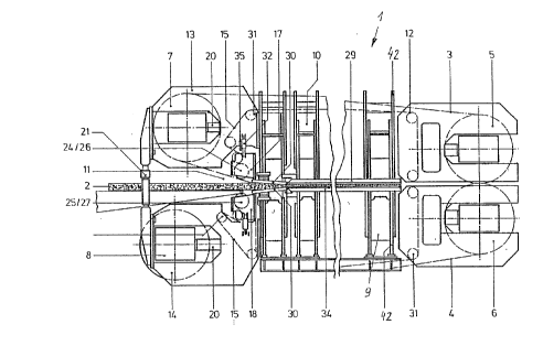
In Fig. 1, continually-operating press 1 comprises a
press bed 9, a moveable press top 10 and guide columns 42
serving to connect upper and lower press portions. The press
gap can be adjusted by moving press top 10 up and down with
the aid of hydraulic piston-and-cylinder assemblies (not
shown) until the desired position is reached. Steel bands 3
and 4 circulate around press bed 9 and press top 10 by
travelling over both drive rollers 5 and 6 and guide rollers 7
and 8. Friction arising between heating plates 29 and 34,
which are located on press bed 9 and press top 10
respectively, and circulating steel bands 3 and 4, is
attenuated by the interposition of a similarly- circulating
roller rod carpet comprising roller rods 12. The latter,
whose axes are oriented transversely relative to the direction
of movement of the steel band, are attached at precisely-
defined intervals to roller chains 15, on both longitudinal
sides of the press. The roller rods, which roll along, on one
side, upon heating plates 29 and 34 of press bed 9 and of
press top 10 respectively, and on the other side along steel
bands 3 and 4, pull material-to-be-pressed 2 in the travel
direction of press 1.
It will be appreciated from Figs. 1 to 4 that roller rods
12 are introduced into the horizontal press plane under
frictional and form-fitting contact by means of feed sprockets
24 and 25 and that two entry-side sprockets 26 and 27 guide
~ O ~ S
link chains 15 into such region, whereby ~eed sprockets 24,
which are located on press top 10 and feed sp~ockets 25, which
are located on press bed 9, as well as entry-side sprockets
26, which are located on press top 10, and entry-side
sprockets 27, which are located on press bed 9, are fastened
to a common axis. Reference number 33 marks the entry tangent
of the feed sprockets 24 and 25 and thus the beginning of
contact of roller rods 12 with steel bands 3 and 4. The manner
of travel of the roller rods on press bed 9 and press top 10
over guide rollers 31 is also indicated.
In roller rod alignment region "c" roller rods 12 are set
in the correct advancement position by means of pilgrim-step
mechanisms 23 comprising toothed racks or teeth serving to
precisely align and to impart to the roller rods the correct
forward movement with even inter-rod spacing.
In Figs. 2 and 3, material-to-be-pressed 2 is introduced
by means of loading belt 36 into entry gap 11 and deposited
via transfer plate 38 onto lower steel band 4 at point
PK=material-to-be-pressed contact. One advantageous embodiment
of entry systems 17 and 18 having pivoting entry-side heating
plates 30 comprises dividing the entry section for roller rods
12, which extends from entry tangent point 33 up to axis of
rotation "e", into three main sub-regions, which are: roller
rod alignment region "c", material-to-be-pressed pre-
compression region "a" and compression region "b". Rolleralignment region "c" has, more precisely, the role of
hydraulically controlling the orthogonal feed of roller rods
12 into the pressing zone. For this purpose, the entry
section beginning at entry tangent point 33 ( = c1) up to 2/3
"c" is straight and, from this point, slightly curved,
preferably with a radius equal to that of the deflection drums
Ru or greater, the effect of which being that, in every angular
position between a = 0 to a = approx. 4~, the steel bands are
continuously pressed against introduction region "c", i.e.,
the roller rods 12 are clamped between the steel bands and the
entry heating plates 30 along this subsection, whereby the
clamping forces, which are hydraulically applied to the steel
205319a
bands 3 and 4, lie in a region of approx. 1-3 bars of pressing
force. This arrangement ensures that the roller rods will, by
means of the roller rod alignment device 23, be guided into
the pressing zone under form-fitting pressure, the inter-rod
spacing being regular. At entry point llc1ll, the roller rods 12
are positioned on steel bands 3 and 4 by means by means of
feed sprockets 24 and 25. Once placed in this position, the
roller rods are then engaged by the roller rod alignment
devices 23. The roller rod alignment section, which extends
up to 2/3 of "c", has a preferably straight design, since the
pilgrim step mechanisms 23 operate in this zone. An elastic,
resilient support is provided to section "c" by means of a
resilient plate 19, which is attached at point "a2" and is able
to swing through a free slewing segment 35 in a sloping region
of entry-side heating plate 30. The frictionless travel of
roller rods 12 along entry region "c", "a", "b", is provided
by a resilient pressure maintenance plate 16 covering the
latter region which, merges only after axis of rotation "e",
with heating plates 29 or 34 via a saw-tooth connection.
Middle region "a" has, as the material-to-be pressed
pre-compression section, the role of further increasing the
pressing force. This middle region is, together with the
latter third of "c", designed with a radius of curvature of
~ = 1 to 2 times the drum radius ~. Entry systems 17 and 18
are, in the region of this section, hydraulically pressed
against steel bands 3 and 4, whereby roller rods 12 are
clamped between the steel bands and pivotable heating plate
30. The hydraulic positioning forces are produced by short-
stroke cylinders 28 and 32 in the zone located after section
2/3 "c" and curved section "a1" to "a2". The technically
required compression force can, up to exit point "a2", be
precisely hydraulically adjusted by means of a computer system
within the range of approx. 3 bars (point "a1") to approx. 20
bars. The hydraulic forces that are exerted practically
vertically upon the steel bands in curved region "a" are
balanced with the tensile forces in the steel bands which are
produced by means of the hydraulic tightening cylinders 20 on
20~31~S
deflection drums 7 and 8. In order to compensate for the
sloped attitude, hydraulic cylinders 28 are fitted with
suitable dome-shaped bases 22. Arranged to the outside of each
of the hydraulic pressure cylinders 28 are hydraulic support
cylinders 32 which are, at the same time, fitted with a
position sensor 43 which measures the cylinder position at any
one time, and therefore permits the angular position to be
regulated by a central processing unit. The hydraulic support
cylinders 28 and 32 are arranged across the width of the press
in order to afford even pressure distribution. Contact with
the material-to-be-pressed PK begins at the forward quarter of
the material-to-be-pressed pre-compression region "a". This
arrangement ensures that material-to-be-pressed 2, will, when
coming in contact with upper steel band 3, be immediately
compressed with a pressure equal to approx. 12.5 bars. Since a
pressing force of 12.5 bars is applied to the material-to-be-
pressed beginning at contact point PK, uneven particle
distribution is no longer able to negatively impact on the
regular advancement of the roller rods into the press.
The role of compression region ':b" is that of ensuring
that the material-to-be-pressed 2 will be compressed even if
in various angular positions ~. The straight section of the
entry-side heating plates 30 running from exit point "a2" up to
the axis of rotation "e" permits pressure to be built up upon
material-to-be-pressed 2, through a short section, whereby the
pressure is increased by hydraulic means from approx. 20 bars
up to a maximum of (in this embodiment example up to 50 bars).
It is technically feasible for this compression section to be
adapted to prevailing operational requirements, e.g., in MDF
applications, correspondingly longer than would be the case
for particle board production, in order to afford a longer
air-expulsion time while transiting the longer process
pathway.
Transfer nose 37 of loading belt 36 is, with respect to
the various heights of the material-to-be-pressed, or rather,
particle board thicknesses, not adjustable, but fixed in a
stationary manner in entry gap 11. Transfer nose 37 is, in
203 31 93
order to be able to follow every movement of the lower entry
system, arranged in front of the transfer plate 38, which
moves about axis 39. This arrangement has the advantage that
the position of the transfer nose, being separated by a great
distance from both lower and upper drums, prevents the
temperatures of steel bands 3 and 4 from affecting the
synthetic material bands of the loading belt 36, in other
words, operational safety is improved because the bands are
permitted to operate at a lower temperature level. This
distance between the bands furthermore constitutes a solid
safety barrier which prevents the heat radiation from causing
widespread damage. Transfer plate 38 can be swung inwardly
and outwardly by means of a lever mechanism whose shape
suggests a parallelogram, which is to say during production
changes, for example, involving switching from one particle
structure or board thickness to another. It is operationally
advantageous that loading belt 36 be reversible so as to allow
it to move against the transport direction of the press so as
to be able to remove the excess pressing material particles
into a container. Simultaneously, then, the remainder of the
particle mass, which is situated upon the transfer plate 38,
can be swung away into the disposal position so that the chip
mass sitting on top of the plate can move of its own accord
onto loading belt 36 and is thus enabled to be transported
backwards into the waste material container. In order to
prevent sagging over the width of transfer plate 38, a number
of height-adjustable support members 41 are located on a
pedestal 40 of lower entry system 18.
Both articulated cross heads 13 and 14, which serve as a
bearing shield for deflection drums 7 and 8, are anchored so
as to be able to pivot on press bed 9 and press top 10.
Deflection drums 7 and 8 can be adjusted relative to each
other by means of two adjustment cylinders 21 arranged along
the longitudinal sides of steel bands 3 and 4. Entry systems
17 and 18 are also arranged so as to be able to slew about
axis of rotation "e" and inside articulated cross heads 13 and
14, so that compression angle ~ of compression gap 11 can be
~0~19a
11
changed by moving entry-side heating plates 30. When
compression angle ~ is changed, the point of entry tangent 33
on feed sprocket 24 or 25 for the roller rods 12 shifts from
the radius of curvature ~ in the latter third of "c" and in
the entire material-to-be-pressed pre-compression region "a"
to the radius of curvature ~ of deflection drum 7 or 8. This
angle is shown as angle B.
Because angle B can be varied, it is advantageous if
roller rod alignment section "c" be resilient so that the
roller rods 12 can, in this region, follow the movement of
entry tangent 33 which is located on the steel band. As Fig.
4 shows, recesses are provided in resilient plates 19 and in
pressure maintenance plates 16 for feed sprockets 24 or 25 for
roller rods 12 and for the pilgrim step mechanisms 23 as well
as for entry sprockets 26 and 27 which serve to properly align
roller rods 12 and guide the guide chains 15 about the press.
The pilgrim step mechanisms 23 are evenly distributed over the
width of the press (minimum number of mechanisms =2) on top or
bottom so as to ensure that the roller rods will enter feed
region "c" orthogonally and evenly spaced. In order to ensure
the safe transfer of the material-to-be-pressed 2 during press
operation, lower material-to-be-pressed contact point PK is
set sufficiently far through a safety distance X in the
direction opposite that of the process direction of the press.
A further advantage of the present invention is that the
roller rods can, independently of the compression applied to
the material-to-be-pressed, be clamped with increasing
pressure against the hydraulically pre-stressed steel bands 3
or 4, between the latter in roller rod alignment region "c",
an arrangement which has the following advantages:
After leaving the roller rod alignment section "c", the
roller rods 12 are subjected to steadily increasing clamping
pressure between "a1" and "a2", whereby pressure build-up in
region "a1" to "a2" is approx. 3 bars = 0.4 x HP ~x of the
press (e.g if the maximum pressure of press is 50 bars, then
the initial pressure in region "a2" is 20 bars).
Due to the clamping pressure, which increases up to
2G5319~
12
material-to-be-pressed contact point PK (a/4) at upper steel
band 3, the irregularities present in the particle mass, which
can be due for example to faulty material distribution, can
have no negative impact on the orthogonal advancement of
roller rods 12 into the press.
Region "a" and "b" is rigid, i.e. has a fixed radius of
curvature RE = Ru and comprises a straight section which is
effectively a part that is connected so as to articulate
around axis of rotation "e". Roller rods 12 advance,
therefore, through both zones "a" and "b" under frictional
contact, after having been pressed under frictional contact
against the steel band in region "c" due to the plate-spring
effect, and are additionally caused to maintain their
orthogonal travel and regular spacing under form-fitting
contact by means of the step-by-step mechanisms 23. The
flexible roller rod entry tangent point 33 has yet another
significant feature: The mid-point of feed sprockets 25 and 27
is connected in a form-fitting manner with the tangent point
33 which allows them to follow the path of movement of tangent
point 33. Similarly, the bearing assembly of step-by-step
mechanisms 23 is connected in a form-fitting manner which
permits them also, being connected to feed sprockets 24 and
25, to follow the resilient motion of tangent point 33.
The proposed solution permits, through servohydraulic
position control, application at entry tangent 33 of a
steadily-increasing clamping force upon the roller rods at
every compression angle, so as to be able to respond to the
particular pressing requirements of the finished product.