Language selection

Search

Patent 2053265 Summary

Third-party information liability

Some of the information on this Web page has been provided by external sources. The Government of Canada is not responsible for the accuracy, reliability or currency of the information supplied by external sources. Users wishing to rely upon this information should consult directly with the source of the information. Content provided by external sources is not subject to official languages, privacy and accessibility requirements.

Claims and Abstract availability

Any discrepancies in the text and image of the Claims and Abstract are due to differing posting times. Text of the Claims and Abstract are posted:

  • At the time the application is open to public inspection;
  • At the time of issue of the patent (grant).
(12) Patent: (11) CA 2053265
(54) English Title: REINFORCING HOLLOW SILL BEAMS OF A VEHICLE BODY
(54) French Title: DISPOSITIF DE RENFORCEMENT DES POUTRES CREUSES DES CARROSSERIES DE VOITURE
Status: Deemed expired
Bibliographic Data
(51) International Patent Classification (IPC):
  • B62D 23/00 (2006.01)
  • B62D 21/07 (2006.01)
  • B62D 21/09 (2006.01)
  • B62D 25/00 (2006.01)
  • B62D 25/20 (2006.01)
(72) Inventors :
  • HELLSTROM, MIKAEL (Sweden)
(73) Owners :
  • AB VOLVO (Not Available)
(71) Applicants :
(74) Agent: MARKS & CLERK
(74) Associate agent:
(45) Issued: 2001-04-10
(86) PCT Filing Date: 1990-04-26
(87) Open to Public Inspection: 1990-11-15
Examination requested: 1997-04-08
Availability of licence: N/A
(25) Language of filing: English

Patent Cooperation Treaty (PCT): Yes
(86) PCT Filing Number: PCT/SE1990/000279
(87) International Publication Number: WO1990/013467
(85) National Entry: 1991-10-25

(30) Application Priority Data:
Application No. Country/Territory Date
8901550-7 Sweden 1989-04-28

Abstracts

English Abstract


A structure for forming hollow beams within a car body.
The beams are stiffened in their transverse direction by
means of cross frames. The cross frames may have a tubular
member arranged transversely to the axial length. At one
end there may be provided at least partially formed side
flanges which are firmly attached to the beam. The length
of the tubular member is preferably at least slightly
shorter than the distance between the opposite longitudinal
sides forming a free space between the other end of the
tubular member and one of the longitudinal sides of the


Claims

Note: Claims are shown in the official language in which they were submitted.


The embodiments of the invention in which an exclusive
property or privilege is claimed are defined as follows:
1. A low weight stiffening tubular cross frame for
reinforcing the interior of a hollow sill beam, which is
located longitudinally along the exterior of an automobile
body, the hollow sill beam being formed by an inner sill
half and an outer sill half, said tubular cross frame
comprising at least two members and having a first and a
second end arranged transversely to the longitudinal axis
of the sill beam, said members including side flanges
attached proximate to said first end of said cross frame,
said side flanges fixedly connected to one of said sill
halves, said tubular cross frame being shorter in length
than the distance between the inner sill half and the outer
sill half, whereby a free space exists between said second
end of said tubular cross frame and the opposite of said
sill halves.
2. The tubular cross frame of claim 1, further
including a sheet lug attached proximate to said second end
of said tubular cross frame for attachment to the hollow
sill beam.
3. The tubular cross frame of claim 2, wherein the
inner sill and the outer sill are two separate and distinct
members, said sheet lug is attached to the hollow sill beam
at a point where the inner sill is attached to the outer
sill.


4. The tubular cross frame of claim 1, 2 or 3,
wherein said members form said tubular cross frame in two
halves joined at a connecting flange, said connecting
flange defining a parting plane diagonally oriented to the
center axis of said tubular cross frame.
5. A stiffening device to protect automobiles during
lateral collision comprising:
an automobile body with a hollow sill beam located
longitudinally along the exterior of said automobile body,
said hollow sill beam having an inner sill and an outer
sill;
a low weight stiffening device for insertion into said
hollow sill beam having a plurality of members forming a
tubular cross frame with a first and second end arranged
transversely to the longitudinal axis of said hollow sill
beam; and
a side flange attached proximate to said first end of said
tubular cross frame, said side flange fixedly connected to
said outer sill;
wherein said tubular cross frame is shorter in length than
the distance between said inner sill and said outer sill,
whereby a free space exists between said second end of said
tubular cross frame and said inner sill.

Description

Note: Descriptions are shown in the official language in which they were submitted.


CA 02053265 2000-O1-20
REINFORCING HOLLOW SILL BEAMS OF A VEHICLE BODY
The present invention relates to reinforcing hollow beams
and in particular to superficially situated hollow beams,
e.g. sill beams, contained in a car body, which beams are
made rigid in the lateral direction by means of transverse
frames.
During lateral collisions the sills of cars are exposed to
large amounts of stress, since they are often exposed
directly to collision forces from the colliding vehicle.
Since the forces also influence parts of the car body
higher up, a torsional moment is generated, which makes the
sill beam and the lateral beam twist upwards and inwards.
Therefore, the car body does not provide the desired
protection against lateral collisions.
The problem has been observed in many quarters and now
there is detailed legislation relating to how much force
the car body should be able to absorb from the side. In
order to counteract the above mentioned torsional
tendencies, there have been attempts to inject isocyanates
into the sill beam. However, in the long run, this causes
problems with moisture and thereby corrosion.
It is commonly known in self-supporting car bodies to
arrange hollow beams, which are made rigid by transverse
frames and/or diagonal frames arranged inside the hollow
1


CA 02053265 2000-O1-20
beams. These beams in fact are effective, but increases
the weight of the vehicle by quite a lot, which is
unacceptable in today's car industry. The division of
hollow beams into a number of smaller cells also leads to
an increasing risk of corrosion.
An object of the present invention is to provide a
stiffening device of the kind mentioned by way of
introduction, which stiffens the car body against lateral
forces during lateral collisions, but also gives an
improved stiffening during pitching and rolling movements.
Other objects of the invention are to provide the
stiffening device with low weight, to permit free passage
of ventilating air, and to prevent corrosion throughout the
beam. Moreover, the structure should be simple, be
suitable for mass production, and be designed such that it
can be handled by a robot. Accordingly, the present
invention relates to a low-weight stiffening tubular cross
frame for reinforcing the interior of a hollow sill beam,
which is located longitudinally along the exterior of an
automobile body. The hollow sill beam is formed by an
inner sill half and an outer sill half. The tubular cross
frame comprises at least two members, and has a first and a
second end arranged transversely to the longitudinal axis
of the sill beam. The members include side flanges
attached proximate to the first end of the cross frame.
The side flanges are fixedly connected to one of the sill
2


CA 02053265 2000-O1-20
halves. The tubular cross frame is shorter in length than
'the distance between the inner sill half and the outer sill
half, whereby a free space exists between the second end of
the tubular cross frame and the opposite of the sill
halves.
The invention will be described in more detail below with
reference to the appended drawings, which illustrate a
20
preferred embodiment, wherein:
FIG. 1 shows in perspective a passenger car body provided
with hollow beams reinforced with cross frames according to
the invention;
FIG. 2 shows in larger scale a section through the sill
beam to the car body shown in FIG. 1; and
FIG. 3 illustrates in perspective a cross frame according
to the invention.
Illustrated in FIG. 1 is a passenger car body provided with
hollow sill beams 11 below the doors 12 and 13, and in
which sill beam a number of cross frames 14 are provided,
the position of which is indicated with reference
designations 15.
The sill beam 11 in the embodiment shown in FIG. 1 and 2
has a section form; which is essentially constant, and
3


CA 02053265 2000-O1-20
which sill beam in cross section has the form of an
irregular polyhedron adapted to the local conditions. The
sill beam 11 consists of two halves 16 and 17, each
provided with mounting flanges 18 and 19, which by means of
spot welding are joined to each other forming a hollow
beam. The vertical parting planes of the beam at the top
and at the bottom are displaced with respect to each other.
To one half 16 of the sillbeam is connected a cross beam 20
and to this mounted a floor 21. 22 designates a sill panel
and 23 a number of cables hidden under the panel.
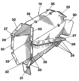
The cross frames inside the sill beam 11 are formed by
tubular members 24 arranged transversely to the
longitudinal axis of the beam. The tubular members are
polygonal shaped in cross section, in the shown embodiment
in the form of an octagon. Even the tubular member 24 is
composed of two halves 25 and 26, the parting plane of
which is diagonally oriented versus the longitudinal
direction of the tube. In the parting plane each half 25
and 26 is provided with connection flanges 27 and 28 which
are connected to each other by means of spot welds 29.
One of the bevelled ends of the tubular member 24 is
provided with two thick side flanges 30 which have the same
inclination as the part of the inside of the beam against
which the side flanges is connected to by means of spot
welds.
4


CA 02053265 2000-O1-20
The tubular member 24 has been given a somewhat shorter
length than the distance between the opposite longitudinal
sides of the sill beam 11, so that between the free end of
the tubular member and one of the longitudinal sides of the
sill beam there is formed a free space. The mounting of
the the other end of the tubular member 24 has been
provided by means of a downfolded or upfolded sheet lug 31,
which is an extension of the bottom part 32 or the top part
35 of the tubular member. The sheet lug 31 is inserted
between the lower connection flanges 18 and 19 of the sill
beam, and fixedly connected with these by spot welding. In
the connection flange 18 and/or 19 are provided, e.g.
pressed pockets, in which the sheet lug may be inserted
during mounting.
In order to better transmit the deformation forces from the
outside of the sill beam to the inside of the same, the
free end of the tubular member is provided with pressure
distributing flanges 33, which transmit the collision
forces to the inner sill beam half 16 and further to the
crossbeam 20 and the floor 21. In order to further stiffen
the tubular member this is preferably provided with a
number of ridge-shaped embossings 34, which are preferably
placed in the foldings. As can be seen from FIG. 2 the
tubular member is designed somewhat smaller than the
internal cross section of the sill beam so that air or a
fluid can freely flow past the tubular members. The
special mounting of the tubular member results in that
5


CA 02053265 2000-O1-20
vibrations of the car body does not give rise to a rattling
noise. Despite their relatively small weight, the tubular
members are very strong cross frames, which effectively
stiffen the sill beam as well as the entire bottom
structure of the car body.
6

Representative Drawing
A single figure which represents the drawing illustrating the invention.
Administrative Status

For a clearer understanding of the status of the application/patent presented on this page, the site Disclaimer , as well as the definitions for Patent , Administrative Status , Maintenance Fee  and Payment History  should be consulted.

Administrative Status

Title Date
Forecasted Issue Date 2001-04-10
(86) PCT Filing Date 1990-04-26
(87) PCT Publication Date 1990-11-15
(85) National Entry 1991-10-25
Examination Requested 1997-04-08
(45) Issued 2001-04-10
Deemed Expired 2006-04-26

Abandonment History

There is no abandonment history.

Payment History

Fee Type Anniversary Year Due Date Amount Paid Paid Date
Application Fee $0.00 1991-10-25
Maintenance Fee - Application - New Act 2 1992-04-27 $100.00 1992-04-21
Registration of a document - section 124 $0.00 1992-05-22
Maintenance Fee - Application - New Act 3 1993-04-26 $100.00 1993-03-15
Maintenance Fee - Application - New Act 4 1994-04-26 $100.00 1994-03-17
Maintenance Fee - Application - New Act 5 1995-04-26 $150.00 1995-03-23
Maintenance Fee - Application - New Act 6 1996-04-26 $150.00 1996-03-21
Maintenance Fee - Application - New Act 7 1997-04-28 $150.00 1997-04-02
Request for Examination $400.00 1997-04-08
Maintenance Fee - Application - New Act 8 1998-04-27 $150.00 1998-04-06
Maintenance Fee - Application - New Act 9 1999-04-26 $150.00 1999-03-19
Maintenance Fee - Application - New Act 10 2000-04-26 $200.00 2000-04-04
Final Fee $300.00 2001-01-10
Maintenance Fee - Patent - New Act 11 2001-04-26 $400.00 2001-09-10
Maintenance Fee - Patent - New Act 12 2002-04-26 $200.00 2002-03-20
Maintenance Fee - Patent - New Act 13 2003-04-28 $200.00 2003-03-18
Maintenance Fee - Patent - New Act 14 2004-04-26 $250.00 2004-03-17
Owners on Record

Note: Records showing the ownership history in alphabetical order.

Current Owners on Record
AB VOLVO
Past Owners on Record
HELLSTROM, MIKAEL
Past Owners that do not appear in the "Owners on Record" listing will appear in other documentation within the application.
Documents

To view selected files, please enter reCAPTCHA code :


To view images, click a link in the Document Description column. To download the documents, select one or more checkboxes in the first column and then click the "Download Selected in PDF format (Zip Archive)" or the "Download Selected as Single PDF" button.

List of published and non-published patent-specific documents on the CPD .

If you have any difficulty accessing content, you can call the Client Service Centre at 1-866-997-1936 or send them an e-mail at CIPO Client Service Centre.


Document
Description 
Date
(yyyy-mm-dd) 
Number of pages   Size of Image (KB) 
Cover Page 2001-03-20 1 41
Representative Drawing 1999-09-24 1 17
Cover Page 1993-11-13 1 17
Abstract 2000-01-20 1 17
Abstract 1993-11-13 1 20
Claims 2000-01-20 2 67
Description 2000-01-20 6 190
Claims 1993-11-13 2 56
Drawings 1993-11-13 2 70
Description 1993-11-13 4 186
Representative Drawing 2001-03-20 1 16
Prosecution-Amendment 2000-01-20 13 417
Correspondence 2001-01-10 1 29
Correspondence 2001-10-25 1 16
Assignment 1991-10-25 7 200
PCT 1991-10-25 18 581
Prosecution-Amendment 1997-04-08 2 72
Prosecution-Amendment 1999-07-23 2 4
Fees 1997-04-02 1 54
Fees 1996-03-21 1 57
Fees 1995-03-23 1 62
Fees 1994-03-17 1 45
Fees 1993-03-15 1 46
Fees 1992-04-21 1 28